FunkTronic 900020 User manual

Interface
Audio, USB, RS232, RS485
Kenwood NEXEDGE

Interface USB/RS232/RS485 eng (24.11.2014)
- 2 -
Kompetent für Elektroniksysteme
Interface USB/RS232/RS485 eng (24.11.2014) - 3 -
Kompetent für Elektroniksysteme
Contents
Technical Data 2
Order Information 2
Sockets + Pin Assignment 3
General Information 3
AF Connection 5
RS485 Interface 5
LEDs 5
Service Interface 6
Monitor Instructions 6
EEPROM Registers 6
Example Configurations 7
Sockets 8
Board Layout 8
Jumper 9
General Safety Information 10
Returning of Old Equipment 10
Release Notes 11
Page
voltage +12V DC
current consumption typ. 50 mA
input impedance line 600 Ohm
output impedance line 600 Ohm
input impedance radio > 8,2 kOhm
output impedance radio < 50 Ohm
max. output level line 850 mV / 600 Ohm (+1 dBm)
550 mV / 300 Ohm (-3 dBm)
400 mV / 200 Ohm (-6 dBm)
max. output level radio: 1,5 V (+ 6dBm)
amplification line -> radio -20 ... +10 dBm
amplification radio -> line -20 ... +10 dBm
weight ca. 110 g
dimensions
W x D x H 100 x 75 x 32 mm
Technical Data
Order Information
Order No. Description
900020 Interface Audio, USB, RS232, RS485
900921 Cable Audio-USB-Interface <-> FT635 ÜLE
900930 Cable Audio-USB-Interface <-> Kenwood NEXEDGE NX-700-E
900923 Programming Cable Audio-USB-Interface

Interface USB/RS232/RS485 eng (24.11.2014)
- 2 -
Kompetent für Elektroniksysteme
Interface USB/RS232/RS485 eng (24.11.2014) - 3 -
Kompetent für Elektroniksysteme
Sockets + Pin Assignment
The Interface Audio, USB, RS232, RS485 is used for the remote control of Kenwood NEXEDGE-
radios. The radios are controlled using a Funktronic Major 4a/5a control panel, that has to be
equipped with the software option Kenwood NEXEDGE. Hereby, the instructions to control the radio
are transmitted via the serial data interface (RS232), the NF is transmitted in an analog way from the
Major to the radio.
General Information
Line RS232 RS485
AF output A - 1
AF output B - 2
RS485 A - 3
GND - 4
free (+12V input) - 5
RS485 B - 6
NF input A - 7
NF input B - 8
4 - free (GND / RS485 B)
3 - RS485 B
2 - RS485 A
1 - free (GND / RS485 A)
6 - free
5 - GND
4 - RS232 TxD
3 - RS232 RxD
2 - free
1 - free
Socket "Line":
Connection to the remote interface
Attention: NF input and output need to be crossed or JP5 - JP8 need to be switched
Socket "RS232":
in normal operation: Connection to the RS232 of the radio or Major
this socket is also used for configuration of the interface
Socket "RS485":
Alternative connection of RS485, if RS485 and AF should be in separate cables.

Interface USB/RS232/RS485 eng (24.11.2014)
- 4 -
Kompetent für Elektroniksysteme
Interface USB/RS232/RS485 eng (24.11.2014) - 5 -
Kompetent für Elektroniksysteme
USB Radio/Major
+5V - 1
Data - -2
Data + - 3
GND - 4
1 - GND
2 - AF output
3 - frei
4 - GND
5 - +12V input
6 - frei
7 - AF input
8 - GND
Radio / Major:
connection to the AF of the radio or Major.
power supply of the interface
USB:
not used
Cables: Connection Cable FT635 ÜLE <-> Interface 900921
Connection Cable Kenwood NEXEDGE NX-700-E <-> Interface 900930
Patch Cable RJ11 (6P4C, 1:1) for RS232 of Major <-> Interface LV.PATCH4_6
Patch Cable RJ45 (1:1) for S/E socket of Major <-> Interface LV.PATCH805
Patch Cable RJ45 (1:1) Line <-> Line LV.PATCH805
Patch Cable RJ10 (4P4C, 1:1) for RS485 <-> RS485 LV.PATCH4_4
5 GND
Pinout
RS232 ST4
1
2
3
4
5
6
3 TxD RS232
2 RxD RS232
RS232 9-pin plug of the PC RS232 socket of the interface
Programming Cable
Attention:
RXD and TXD are switched
compared to the Major!

Interface USB/RS232/RS485 eng (24.11.2014)
- 4 -
Kompetent für Elektroniksysteme
Interface USB/RS232/RS485 eng (24.11.2014) - 5 -
Kompetent für Elektroniksysteme
RS485 is a differential 2-wire (+GND) data interface for 2 or more participants. The maximum length
is about 1000m. Both ends of the bus need to be terminated with 120 Ohm, branches should be
short and should not include a terminating resistor.
The RS485 is already equipped with the suitable terminating resistors. For few and short connection
lines, these can remain in place. In other cases or if connection problems are encountered the surplus
resistors need to be removed (R14-R16). Another possibility to improve the connection is to reduce
the rate of the data transfer.
Ex factory, the RS485 is part of the "Line" connector and, thus, transferred in the same cable as the
AF lines. Hence, only one cable is necessary to connect 2 interfaces. Depending on the used cables,
the cable length and the number of interfaces, coupling of the data telegrams with the AF lines might
occur. In this case, the RS485 sockets can be connected using a separate cable. To disconnect the
RS485 lines of "Line" socket, open JP1 and JP2.
RS485 Interface
The LEDs at the socket "Radio/Major" (green on the right and yellow on the left) display the
different statusses of operation:
- left LED shortly flashes once per second: interface is trying to establish a connection to the Major
or the radio
- right LED is on: connection to the Major established
- left LED is on: connection to the radio established
If a connection is eestablished, the LEDs are flashing for a short time on receiving a telegram. The
left LED flashes for telegrams from the radio, the right LED flashes for telegrams from the Major.
LEDs
The interface has 2 AF inputs and outputs. The input and output at the socket "Radio/Major" is
single-ended (one pin is GND), while the input and output of the socket "Line" is potential-free.
Amplification is possible in both directions from -20dB to +10dB and can be adjusted using the
service interface.
AF Connection

Interface USB/RS232/RS485 eng (24.11.2014)
- 6 -
Kompetent für Elektroniksysteme
Interface USB/RS232/RS485 eng (24.11.2014) - 7 -
Kompetent für Elektroniksysteme
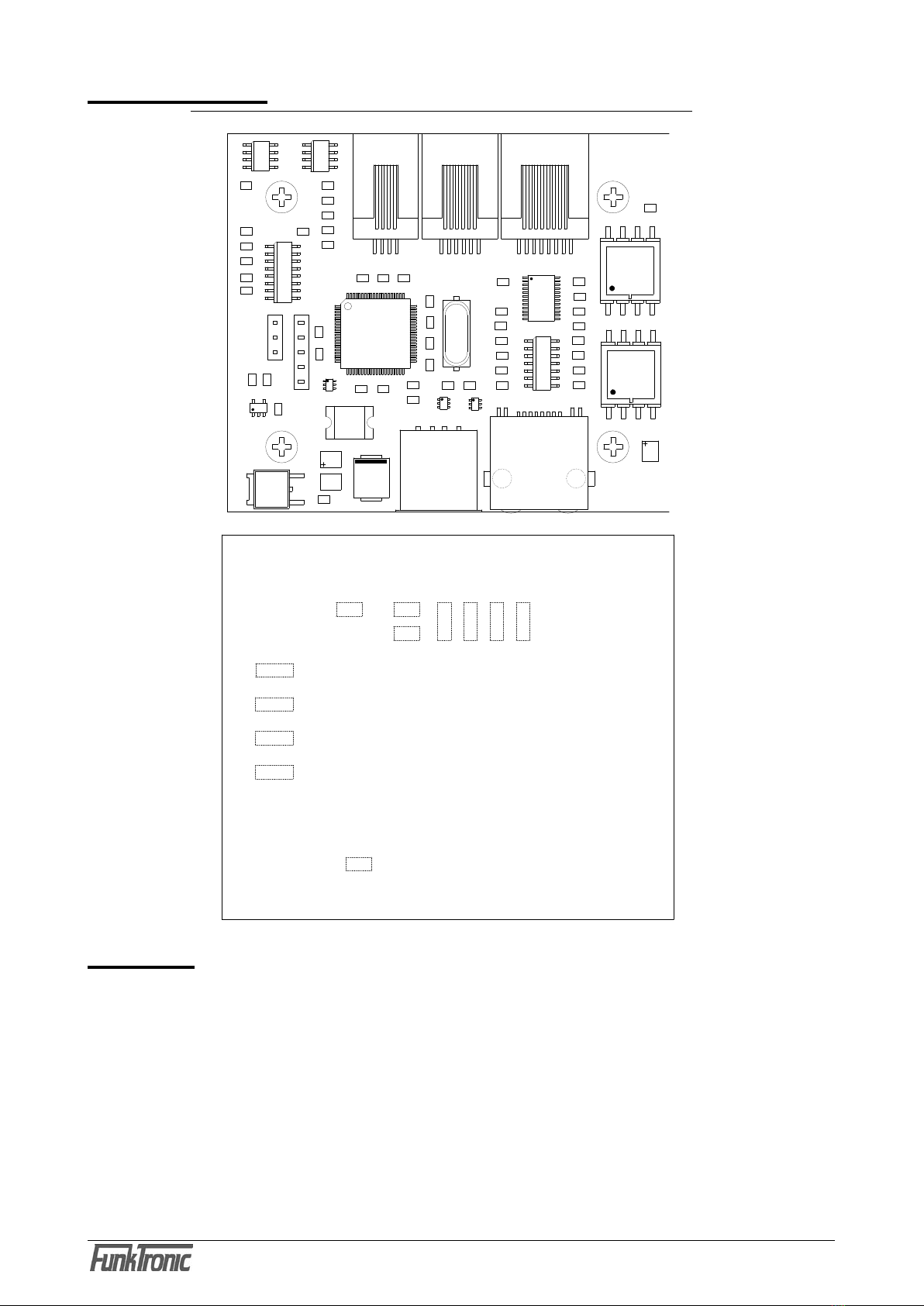
The service interface is used to program the EEPROM registers and to adjust the potentiometer.
To use the RS232 interface for service purposes, it has to be activated at power-on of the device.
Activation is no longer possible after the interface is connected to the Major or to the radio.
When the terminal program is connected to the interface, the telegram "gk00" can be seen, which
is sent every second. Now, one hast to blindly type the activation sequence to activate the service
interface:
1.) press together button "Ctrl" + button "B"
2.) text input: "monitor" (caps lock must be deactivated - only small letters allowed)
3.) press together button "Ctrl" + button "C"
If the activation was successful, the start text of the monitor is displayed. Sending of the "gk00"
telegrams is suspended for 10 seconds after the last character that the interface receives from the
terminal program. After this, the telegram reappears, but can be simply ignored and has no influence
on the input from the terminal.
Monitor Instructions
In order to excercise a monitor instruction, type the respective characters, confirmed with Enter/
Return.
Rxxx.......................... read register xxx
Pxxx yyyyyyyy........... program register xxx with yyyyyyyy
A............................... adjust potentiometer
Q............................... software reset
X............................... quit monitor
Before connecting the interface to a Major or a radio again (e.g. to check adjusted potentiometer
values), you need to quit the service monitor using the "X" instruction. This way, the monitor can
be reactivated simply by pressing Enter/Return again. If the monitor is no longer needed and the
interface is intended for normal operation, the monitor must be left using the software reset "Q".
Alternatively the interface can be switched off and on again.
!!! The radio should not be operating while the service monitor is not completely deactivated. This
may result in malfunctions that can only be fixed by restarting the whole radio system !!!
EEPROM Registers
Register 000 Digit 1: Baud rate of the RS485 interface, set ex factory to: E (230400)
Wert
0 1 2 3 4 5 6 7
Baud 4800 9600 14400 19200 28800 38400 57600 76800
Wert 8 9 A B C D E F
Baud 96000 115200 128000 134400 161280 201600 230400 249600
Higher bau rates result in reduced reaction times, lower baud rates allow for transmissions over
longer distances. The baud rate has to be programmed equally for all interfaces that are connected
to the RS485 bus.
Service Interface

Interface USB/RS232/RS485 eng (24.11.2014)
- 6 -
Kompetent für Elektroniksysteme
Interface USB/RS232/RS485 eng (24.11.2014) - 7 -
Kompetent für Elektroniksysteme
Example Configurations
RS232
Audio,
UB
3
/
/
6
Single control panel connected to the radio (remotely)
Several control panels connected to one radio
RS232
3
/
/
6
RS232
Audio,
UB
3
/
/
6
8 Audio/RS485
/
RS232
3
/
/
6
RS232
Audio, UB
3
/ /
6
/8
If several control panels are used to control a single radio, the connection is realized with a
Distribution Frame DMR. Here, the RS485 lines are connected in parallel.
Major 4a
Major 4a
Major 4a
Audio, UB
Audio/
RS485
Line
Line
Radio/
Major
Radio/
Major
Audio,
UB\8
Line
Line
Radio/
Major
Radio/
Major
Audio/
RS485
8
/
Audio/
RS485
Line
Radio
Radio/
Major

Interface USB/RS232/RS485 eng (24.11.2014)
- 8 -
Kompetent für Elektroniksysteme
Interface USB/RS232/RS485 eng (24.11.2014) - 9 -
Kompetent für Elektroniksysteme
Board Layout
Sockets
ST1 - USB
ST2 - Major / Radio
ST3 - Data / NF Line
ST4 - RS232
ST5 - RS485
Blatt
File
Check
Drawn
(C) Alle Rechte vorbehalten
Lageplan
D 36381 Schluechtern
Funk Tronic GmbH
USBINT
Pechura09.11.09
1
1
USBINTLeiterplatte USB/RS232/RS485
Interface
Moeller09.11.09
C30
U7
U8
C18
C17
C19
C20
C16
C14
C12
C15
C13
C11
C22
C25
C26
C27
C24
C28
C29
C9
C8
C7
C1
C4
C2
C3
C5
C6
R10
R6
R7
R8
R5
R9
R4
R3
R13
R16
R14
R15
41
ST5
R18
R19
R20
R17
R2
R1
R11
1
3
4 5
6
7
8
2
T2
ST7
8 1
ST3
6 1
ST4
8
12 9
1
ST2
Q1
U3
U11
U10
D1
C21
U5
1
ST6
U6
U9
C23
U2
C10
U4
F1
R12
1
ST1
U1
1
3
4 5
6
7
8
2
T1
JP7
JP8
JP6
JP5
JP9
JP10
JP11
JP4
JP3
JP2
JP12
JP1
11
11
1
1
1
1

Interface USB/RS232/RS485 eng (24.11.2014)
- 8 -
Kompetent für Elektroniksysteme
Interface USB/RS232/RS485 eng (24.11.2014) - 9 -
Kompetent für Elektroniksysteme
Jumper
JP1 - connects RS485 A to pin 3 at ST3 (ex factory: jumper is set)
JP2 - connects RS485 B to pin 6 at ST3 (ex factory: jumper is set)
JP3 - connects the +12V-input to pin 5 at ST3 (ex factory: jumper is open)
JP4 - connects GND to pin 4 at ST3 (ex factory: jumper is set)
JP9 - connects RS485 A(1-2) or GND (2-3) to pin 1 at ST5
(ex factory: jumper is open)
JP10 - connects RS485 B (1-2) or GND (2-3) to pin 4 at ST5
(ex factory: jumper is open)
Jumpers JP5, JP6, JP7 and JP8 configure the AF in-/outputs of the "Line" (ST3). Inputs and outputs
can be switched, so that standard patch cables can be used for the connection of 2 interfaces.
JP5/JP6 and JP7/JP8 set to 1/2 (ex factory setting)
AF-output to pins 1 and 2
AF-input to pins 7 and 8
JP5/JP6 and JP7/JP8 set to 2/3
AF-output to pins 7 and 8
AF-input to pins 1 and 2

Interface USB/RS232/RS485 eng (24.11.2014)
- 10 -
Kompetent für Elektroniksysteme
Interface USB/RS232/RS485 eng (24.11.2014) - 11 -
Kompetent für Elektroniksysteme
Please read the operating instructions carefully before installation and setup.
The relevant regulations must be complied to when working with 230V line voltage, two-wire-
lines, four-wire-lines and ISDN-lines. It is also very important to comply to the regulations
and safety instructions of working with radio installations.
Please comply to the following safety rules:
- All components may only be mounted and maintained when power is off.
- The modules may only be activated if they are built in a housing and are scoop-proof.
- Devices which are operated with external voltage - especially mains voltage - may only
be opened when they have been disconnected from the voltage source or mains.
- All connecting cables of the electronic devices must be checked for damage regularly
and must be exchanged if damaged.
- Absolutely comply to the regular inspections required by law according to VDE 0701
and 0702 for line-operated devices.
- Tools must not be used near or directly at concealed or visible power lines and conductor
paths and also not at and in devices using external voltage – especially mains voltage -
as long as the power supply voltage has not been turned off and all capacitors have been
discharged. Electrolytic capacitors can be still charged for a long time after turning off.
- When using components, modules, devices or circuits and equipment the threshold
values of voltage, current and power consumption specified in the technical data must
absolutely be complied to. Exceeding these threshold values (even if only briefly) can
lead to significant damage.
- The devices, components or circuits described in this manual are only adapted for the
specified usage. If you are not sure about the purpose of the product, please ask your
specialized dealer.
- The installation and setup have to be carried out by professional personnel.
Returning of Old Equipment
According to German law concerning electronic devices old devices cannot be disposed off
as regular waste. Our devices are classified for commercial use only. According to § 11 of
our general terms of payment and delivery, as of November 2005, the purchasers or users
are obliged to return old equipment produced by us free of cost. FunkTronic GmbH will
dispose of this old equipment at its own expense according to regulations.
Please send old equipment for disposal to: FunkTronic GmbH
Breitwiesenstraße 4
36381 Schlüchtern
>>> Important hint: freight forward deliveries cannot be accepted by us.
2 February, 2006
Subject to change, Errors excepted
General Safety Information

Interface USB/RS232/RS485 eng (24.11.2014)
- 10 -
Kompetent für Elektroniksysteme
Interface USB/RS232/RS485 eng (24.11.2014) - 11 -
Kompetent für Elektroniksysteme
Release Notes
Oct-09, 2014 - translation of German version dated from Aug-21, 2014
Table of contents
Other FunkTronic Recording Equipment manuals