Taxa Outdoors 2022 Mantis User manual

7930 Blankenship Dr. Houston, TX 77055
Mantis Owner’s Manual
2022
©2022 TAXA INC. v.4.2.010122

Welcome
Safety
Overview of Safety Precautions
Pre-Travel Checklist
Interior
Exterior
Considerations
Habitat Overview
Troubleshooting
General Care & Maintenance
Frame and Chassis
Hitch Couplers
Safety Chains
Jack
Tires and Wheels
Brake Adjustment
Sealants
Tent Sides
Ceiling, Interior Walls, Countertop
Faucets and Fixtures
Fabric and Upholstery
Checklist
Hitching
Loading & Towing
Terms
General Weight Considerations
Weight/Load Distribution
Towing
Safety Chains
Breakaway Switch
Tire Pressure
Brakes
Lights
Leveling
General Towing & Driving
Swaying & Fishtailing
Gradual Braking
Minimize Quick Steering Movements
Brakes
Breaking-In Brakes
Brake Controller
Connector
Braking Tips
Brake Adjustments
Tires
Overview
Fundamentals
Terms
Load Range
Tire Tread
Replacement
Repair
Tire Pressure & Load Limits
Tire Pressure Steps
Important Reminders
Tire Safety Checklist
Wheels
Wheel Nut Torque
Wheel Nut Torque Adjustment
Pre-Trip Torquing Procedure
Balancing, Alignment, & Lubrication
Site Selection & Setup
Site Selection
Leveling & Stabilization
Habitat Setup
Ventilation & Moisture
Ventilation
Moisture & Condensation
Electrical
12V DC Overview
7-Pin Connector
120V Circuit Breakers
Battery
Battery Installation
Inspection & Monitoring
Charge Controller
Charging
Storage
Dead Batteries
Appliances & Fire Extinguisher
Refrigerator
Fire Extinguisher
Smoke Detector
Carbon Monoxide Detector
Electrical Diagrams
Plumbing
Fresh Water
Water Pressure
Maintenance & Sanitation
Truma Combi
Water Pump
Water Heater
Filling Fresh Tank
city water systems
connecting to city water
wastewater system
Emptying Grey Tank
Outdoor Shower and Hose
Routine Sanitation Process
Emptying Water Heater
Plumbing Diagrams
Optional Bathroom
Roof & Tent Sides
Roof Opening & Closing
Installing / Removing Tent Sides
Awnings
Tent Windows
Extreme Weather
Plumbing System
Insulation & Heat
Battery & Electrical System
Extreme Cold & Heat
Winterization
Interior
Chassis
Exterior
Movement
Plumbing System
Electrical System
Bringing Out of Storage
Authorized Dealers
Limited Warranty
4
5-6
6
7
7
7
7
8-13
14-15
16-18
16
16
16
16
16
16
16
17
17
17
17
17
18-20
21-22
21
21
21
22
22
22
23
23
23
23
23
23
23
23
24
24
24
24
24
24
25-26
25
25
25
25
25
25
25
25
26
26
26
27
27
27
27
27
28
28
28
28
29
29
29
30-32
30
30
30
30
31
32
32
32
33
33
33
33
33
33
33
34-41
42-53
42
42
42
43
43
43
43
44
44
44
44
44
45
45
46
51
52-53
52
52
53
53
54
54
54
54
54
55
55
55
55
55
55
55
56
57
58
Table of Contents
OUT IS IN™

4 5
©2022 TAXA INC. v.4.2.010122 ©2022 TAXA INC. v.4.2.010122
YOUR OWNER’S MANUAL
Make this Owner’s Manual a permanent part of your habitat, download it to a smart device you carry with
you or print it out to keep it with the habitat at all times. Keep the manuals, stickers, and tags associated
with your habitat’s items, add-ons, appliances, and equipment in the habitat as well for easy reference.
All manuals, including components with pass thru warranties etc., are available on our website on the
manuals page - https://taxaoutdoors.com/manuals/
This manual is not intended to be inclusive of every operational aspect of your unit. It should be
utilized and referenced by you in conjunction with the separate, additional manuals provided by the
manufacturers of the different components, component parts, appliances, add-ons, systems, and
accessories in your unit. Your unit will contain any such manuals provided to Taxa Inc. by the specic
component part, appliance, add-on, system, and accessory manufacturer. Please read them to gain a
more complete understanding of the operation and maintenance of the products and appliances installed
in your habitat.
READ THE ENTIRE MANUAL AND OBEY ALL CAUTION, WARNING, DANGER AND OTHER SAFETY-
RELATED STATEMENTS PRIOR TO OPERATING YOUR HABITAT.
PLEASE NOTE
This Owner’s Manual contains the most up-to-date product information available at the time of
publication. However, due to continuous product development, innovation, and improvements, Taxa Inc.
reserves the right to make changes in production techniques/processes, product materials, product
specications, and components. Such changes may be made without prior notice or any obligation upon
Taxa Inc. to make corresponding changes or improvements in or upon its already manufactured, installed
and/or sold habitats and/or products. Please visit our website at www.taxaoutdoors.com, https://
taxaoutdoors.com/manuals/ to check for manual updates and our current manual.
SAFETY TERMS
We have included various safety messages in this manual, all of which are important. Please read and
obey them. The following are safety-related terms and symbols referred to in this manual and their
corresponding meanings/denitions:
DANGER indicates an imminently hazardous situation that, if not avoided, will result
in death or serious injury.
WARNING indicates a potentially hazardous situation that, if not avoided, could
result in death or serious injury.
CAUTION indicates a potentially hazardous situation that, if not avoided, may result
in minor or moderate injury.
NOTICE is used to address practices not related to personal injury. This applies
to hazardous situations involving property damage or important information
regarding the maintenance of your vehicle.
Welcome!
Congratulations on your new habitat!
We hope you go somewhere we have never been. Then we hope you share it with us
and our (your) community.
We hope you stay safe and sane and make the best of every new adventure. These days
are strange and hard but the outdoors always beckons and always refreshes.
The habitat has a new modular storage system of spaces and crates that we hope you
love. It is designed to stow ubiquitous items safely and in their place AND allow you
to do the same with the odd or special items you and only you bring to the great out-
doors. It is designed to let you live indoors and out as seamlessly as we can devise to
date. We have a new orange tent that will revive a favorite view of mine – habitats glow-
ing like gentle lanterns in the night – and the orange also harkens back to Taxa’s orig-
inal tent color. The same tent has a new front window where both the solid panel and
screen can be unzipped, giving you unfettered access to the front roof portion from
the inside of your habitat. I suppose the same goes for chipmunks and marmots so be
aware….
Buying a habitat is different than buying a vehicle – you don’t just hitch up and go –
plotting and planning and outtting and optimizing is part of the fun. Taxa habitat is a
product of course but it is even more an investment in your lifestyle. You grow into it.
We have a set of wonderful Habitat Specialists and an even more wonderful community
that will help!
Please support our nations’ park systems. It takes work to keep things wild and we are
an essential part of that work as users, as stewards, as advocates. Please take with you
only what you need and leave nothing behind!
As ever:
It is important that you thoroughly review this Owner’s Manual. Please consult it any-
time you have a question regarding the safe use, operation, or maintenance of your
habitat and its systems and components. Understanding how they work is an important
part of having a fun, safe travel experience.
We want your rst and every adventure to be great. Have a practice session in your
driveway. Hitch that habitat up and drive it around the block. Get comfortable. Ask
questions! Get answers to any questions, issues or problems that arise during your
practice. Get answers from the community, from our FAQs and specialists – send us an
email . Give us a call or email us at customerservice@taxaoutdoors.com. Many ques-
tions can be answered quickly and easily and save you a lot of hassle.
Best,
Garrett Finney,
TAXA Founder

6 7
©2022 TAXA INC. v.4.2.010122 ©2022 TAXA INC. v.4.2.010122
SAFETY
OVERVIEW OF SAFETY PRECAUTIONS
You’ll nd various safety-related references, discussions, and instructions throughout this owner’s manual,
and all of them are important. This overview is not an exhaustive list of the safety issues discussed or
contemplated in this manual. Please carefully read and follow all safety issues discussed in this manual.
If you have any questions regarding habitat safety issues, please contact your dealer and/or Taxa Inc. -
customerservice@taxaoutdoors.com takes you to all of us – general questions, service, warranty, sales)
The following is a broad snapshot of a few of the more common safety instructions/discussions/issues in
the use and operation of your new habitat:
• Be sure load/cargo weight does not exceed your GVWR and that weight is
distributed properly before travel. Please refer to the “Loading” section.
• Fully close-up and lock your habitat before towing to ensure efcient and safe
transportation.
• Be sure safety chains and breakaway switch have been properly attached and
secured as part of your hitching up process.
• Be sure to have a qualied technician conduct the maintenance, service, and
adjustments on your brakes periodically and as needed. Do NOT travel until all
brake problems, if any, are xed. See “Brakes” section.
• Test your blinkers, brakes and lights before towing on a public road, conrming
that they are working properly and in synchronization.
• Do not allow passengers to ride in the habitat during travel The transport of
people puts their lives at risk and is illegal.
• Be vigilant in your tire inspection and maintenance. Properly maintained tires
improve the steering, stopping, traction, and load-carrying capability of your
habitat and tow vehicle. Under-inated tires and overloaded vehicles are
major causes of tire failure. Please refer to “Tires’’ section for a more detailed
discussion on your tires and tire safety.
• Keep your habitat well-ventilated. Please refer to the “Ventilation” section for
details.
• Clean your potable water hose, and drain and clean holding tanks periodically
and / or as needed.
• Be sure all electrical uses and activities involve proper grounding.
• Reduce shtailing & sway. Excessive sway of your travel habitat can lead to
the rollover of the habitat and tow vehicle, resulting in serious injury or death.
This is usually due to incorrect loading of the habitat but can also result
from road conditions or can indicate habitat damage. You may choose to
install a separately purchased sway control device to help reduce sway. Be
sure to contact your dealer or Taxa Inc. if you have any questions regarding
sway control device alternatives. Please also refer to the sway and shtailing
discussion in the “Towing” section.
PRE-TRAVEL CHECKLIST
INTERIOR
• Turn off all switches at the kitchen switch panel or on the
ceiling.
• Turn off and close all appliances, if not in use. You may keep
the refrigerator on while driving.
• Be sure your cargo berths are secured, and close and latch all
windows
• Be sure the roof top is closed and latched properly at all
locations from inside and outside.
• Be sure tent fabric is secured but not pinched.
• Be sure the shoreline power cord, 7-pin connector and hoses
are secured (and properly attached, if applicable).
• Close and lock both doors.
EXTERIOR
• Be sure the stabilizer jacks and door step are fully raised and
secured.
• Be sure wheel lug nuts are tight and secure.
• Check that all tow vehicle and habitat lights and brakes are
working in synchronization.
• Check brakes with multiple applications in an empty parking
lot.
• Conrm the brake controller, if any, is operating properly.
• Be sure the hitch assembly is secure, and that safety chains
and breakaway switches have been properly attached.
• Check underneath habitat for any damage or displacement.
• Emptying water tanks prior to travel will decrease tow weight
and improve fuel efciency of your tow vehicle.
WARNING: DO NOT ALLOW ANYONE TO RIDE IN HABITAT WHILE IT IS BEING TOWED.
Note: This is not an exhaustive list nor is it intended to be. Use common sense when
preparing for a trip and all other helpful resources available to you.
OTHER IMPORTANT PRE-TRAVEL CONSIDERATIONS
• Be sure to pack wheel chocks and blocks.
• Be sure roof rack cargo, if any, is secure.
• Be sure to monitor your battery’s charge before and during
your trip. Charge battery before traveling, if necessary.
• Read and follow the manual and all pertinent instructions
provided to you by your tow vehicle manufacturer.
• Be sure the tow vehicle is operating fully before any trip,
correcting any problems before travel.
• Bring a ashlight and batteries.
• Make sure your cell phones are charged and that you have
phone chargers.
• Bring extension cords, if necessary.
• Take a spare tire.
• Check for any potential re hazards, and eliminate them, if
any.
• Weigh your load before the trip, making sure it does not
exceed your GVWR.
• Contact your dealer or Taxa Inc. if you have any questions
before your trip.

8 9
©2022 TAXA INC. v.4.2.010122 ©2022 TAXA INC. v.4.2.010122
HABITAT OVERVIEW HABITAT OVERVIEW
INTERIOR
The Mantis is for anyone and everyone. We thought mostly of families but I know all sorts of families
so I should be a little more specic!. It can sleep up to four full sized people in its berths – two of those
people can share a double bed with the others in single bunks. Add hammocks and or a rooftop tent
and you could theoretically get up to 8 in and on there - kids, grandkids, agile dogs and ferrets, more
friends, a Nubian goat. We at Taxa are agnostic about who and what you camp with. We just love to
help you get there.

10 11
©2022 TAXA INC. v.4.2.010122 ©2022 TAXA INC. v.4.2.010122
12V Outlet Fuse, 5A
LED Light Fuse, 2A
LED Light Fuse, 2A
LED Light Fuse, 2A
LED Light Fuse, 2A
12V Fridge Outlet Fuse, 5A
USB Fuse, 5A
12V Outlet
USB Outlet
Front Light
Ceiling Light
Step Safety Light
Exterior Light
HABITAT OVERVIEW
WFCO Power Center
Battery Cut-Off
TRUMA and Plumbing
Access Panel
Propane and CO
Leak Detector
Battery
Compartment
Voltmeter
GFCI Outlet
12V Outlet
TRUMA Controls
Switches / Fuses
TRUMA Hot
Air Vents (x3)
Please familiarize yourself with the controls, features, and nctionality of your habitat using the
following diagrams.
HABITAT OVERVIEW
USB Outlet
Reading Light Fuse, 5A
Control Panel Fuse, 1A
Furnace Fuse, 10A
Stove Fuse, 3A
TRUMA Control Knob
12V Outlet
Temperature Sensor
Water Pump, 7.5A
Kitchen Light, 2A
Rear Light, 2A
2022 Mantis Kitchen Diagram
2022 Mantis Truma Control Panel
2022 Mantis Entryway Switchplate

12 13
©2022 TAXA INC. v.4.2.010122 ©2022 TAXA INC. v.4.2.010122
Disengage AC Driving
Locks to allow the AC
unit to slide.
AC unit slides into and out of the unit to provice the AC
with airflow while minimizing the width of the Mantis.
HABITAT OVERVIEW
GFCI Outlet
USB Outlet
Cord Hooks
Storage Locker
Located behind
Storage Tower
HABITAT OVERVIEW
Both AC Driving Locks
must be engaged
before driving.
2022 Mantis Storage Locker Diagram
2022 Mantis AC Locking
2022 Mantis AC Usage

©2022 TAXA INC. v.4.2.010122 ©2022 TAXA INC. v.4.2.010122
14 15
TROUBLESHOOTINGTROUBLESHOOTING
Plumbing
Description Likely cause Fix
Sink backed up
Gray water tank full a. open gray water valve to drain
Sink Trap clogged Remove kitchen access panels to access plumbing (secured with three
bolts). Squeeze or remove trap to loosen clog.
Sink leak Loose connection Inspect sink drain, p-trap, and drain hose, tighten where necessary
Shower leak – Exterior Loose connection, sand / grit in
quick disconnect Flush out exterior quick disconnect with water to remove grit
Shower leak - Interior Loose connection(s) or bad
washer
Tighten connection between shower wand and hose; between hose and
faucet; remove faucet and replace rubber washer.
Shower drain leak Loose connection remove access panel below shower, visually inspect and tighten
connections.
Plumbing leaks behind
kitchen cabinetry Loose connection Pressurize system, observe leak spot. Tighten hose clamps and or push
pull fittings.
Plumbing leaks under
habitat Loose connection Check plumbing connections in problem area and tighten if loose
Water heater leak loose connection or over
pressured water.
Check push pull connectors at heater (push and pull them to check if one
is loose!) at heater. Remove and re-insert. Ensure city water is below
125PSI and is being regulated by pressure regulator at inlet.
Low water pressure Drawing air in water supply line
Tighten line by checking connections back to water tank from sink; tighten
or re-connect. Check connection also beneath habitat. Sometimes you can
hear air entering line when water pump is turned on.
Fresh tank won’t fill
Hose improperly inserted Use fill line connector
Vent blocked up or crimped
Blow out vent line (small hole just above fill area)
If crimped, remove bend in line. (accessible by removing service panel
beneath Vberth)
Water pump not working
Check fuse beneath water pump
switch at kitchen.
Replace pump
Water heater not working
no hot water
Verify that furnace (heat) is working. Check LCD control panel to make
sure setting is correct, not on a timer that timed out. Check top of furnace
unit itself to verify that small switch is in ON position. Note that water
heating speed depends on inlet temp.
no power (no LEDs on unit) Check fuse on switch plate at kitchen.
if propane
Check GFCI breaker where heater plugs into outlet beneath cabinet.
Reset.
check TRUMA manual troubleshooting
if propane check propane supply and valves
Electrical
Description Possible cause Fix
120v circuit breaker pops Wet extension cord Dry cord, reset breaker.
Battery not charging
(see LED volt monitor:
– a well charged battery is
between 12.6 and 12.8V
- a charging battery is ~13.
4V if habitat is plugged in to
120v
- + ~.2V if solar or vehicle
charging)
7-pin connection short
Check tow hitch connection and wiring. Verify that interior volt meter jumps
up in voltage when car is turned on and 7 pin is in position. Check for
loose or burnt wires in connector.
Check habitat end connection
Converter/
charger Test converter charger; replace converter element if necessary
Check 30 amp fuses at WFCO
Battery charge
Test battery
Circuit interruption Overloaded circuit Throw circuit breakers or replace fuses.
Lights flickering Battery not charged Check battery charge
Fridge not functioning
Battery not charged Check battery charge
Blown fuse in fridge plug Check inline fuse in frig plug (green LED should be on in plug when
functioning)
Blown fuse in WFCO Check fuse position #4
check ON/ OFF LEDs inside of frig, top left are on/off and temp settings
Ceiling lights not functioning Blown fuse in WFCO Check fuse # 2
Kitchen 12v outlet not
functioning Blown fuse in WFCO Check fuse #3
Exterior 12v outlet not
functioning Blown fuse in WFCO Check fuse #1
Kitchen counter lights not
working popped circuit Check glass fuse beneath switch
Red step light not
functioning popped circuit Check glass fuse beneath switch
Hot Water Heater not
turning on popped circuit Check glass fuse beneath switch
Water pump not turning on popped circuit Check glass fuse beneath switch
Exterior Leaks
Description Possible cause Fix
Roof leak
Roof latch loose Adjust interior roof latches, tent side, ensure fabric and window toggles are
preventing best seal
damaged weatherseal inspect, replace if required
Leak through tent side Tent side not installed properly.
Tent window open during rain. Reinstall tent side (see SITE SELECTION AND SETUP)
Doors, Windows, Tent Sides, and Graphics
Description Possible cause Fix
Side door gap Missing/misaligned door gasket Install door gasket
Key will not turn in cylinder dirt or grit Lubricant such as WD40
Window will not close dirt or grit Lift window to full open position. It should now go all the way down.
Repeat if required
Window gap adjust latches interior latches have two locked positions, one closes to weather and dust,
other leaves 1/8” gap
Broken window arm Misuse Install new part by pressing pin hole, removing broken arm, and replacing

16 17
©2022 TAXA INC. v.4.2.010122 ©2022 TAXA INC. v.4.2.010122
The best storage procedure, if the habitat is
stored out of doors, is to park it under the cover
of a roof, cover, or tarp. Keep your tent sides dry
when possible to avoid prolonged exposure to
mildew, which may damage them. If you have
mildew, use the following recipe:
1. Mix 1 cup of salt, 1 cup of lemon juice,
and 1 gallon of hot water
2. Wash moldy/mildew areas of the tent
with a sponge
3. Let dry
Be aware that wind, water, sun, pollution, debris
and neglect may all degrade your tent side fabric
over time. Have the tent side repaired at the rst
sign of fraying or tearing. Take care to protect the
fabric from metal parts.
CEILING, INTERIOR WALLS, COUNTERTOP
Clean with soap or other mild, non-abrasive
cleaner, warm water, and a damp cloth. Do NOT
use strong, harsh chemicals, and limit water/
moisture exposure to ceiling and walls when
cleaning. Excessive moisture may damage the
ceiling and walls. Be sure to thoroughly dry the
ceiling and walls after cleaning. Avoid using
abrasive pads and scouring powders, which may
dull surfaces and increase exposure to future
staining.
Remember to use a chopping block or cutting
board when using knives on the countertop. Pots
and pans straight from the burner or oven should
be placed on lined hot pads and not directly on
the counter surface.
FAUCETS AND FIXTURES
Use only a damp soft cloth or sponge to clean.
Do not use abrasive cleaners or materials as they
may damage the nish.
FABRIC AND UPHOLSTERY
Berth cushions are made of a xed marine-
grade vinyl. Clean them with a damp cloth and
mild soap or other cleaning product. Be sure to
dry thoroughly after cleaning. Folding couch
cushions are made of nylon which may be
machine washed cold and air dried.
NOTE: The following checklists will help make
sure that you inspect and maintain your habitat
regularly. This list is not meant to be exhaustive.
You should inspect and maintain your habitat
often and thoroughly.
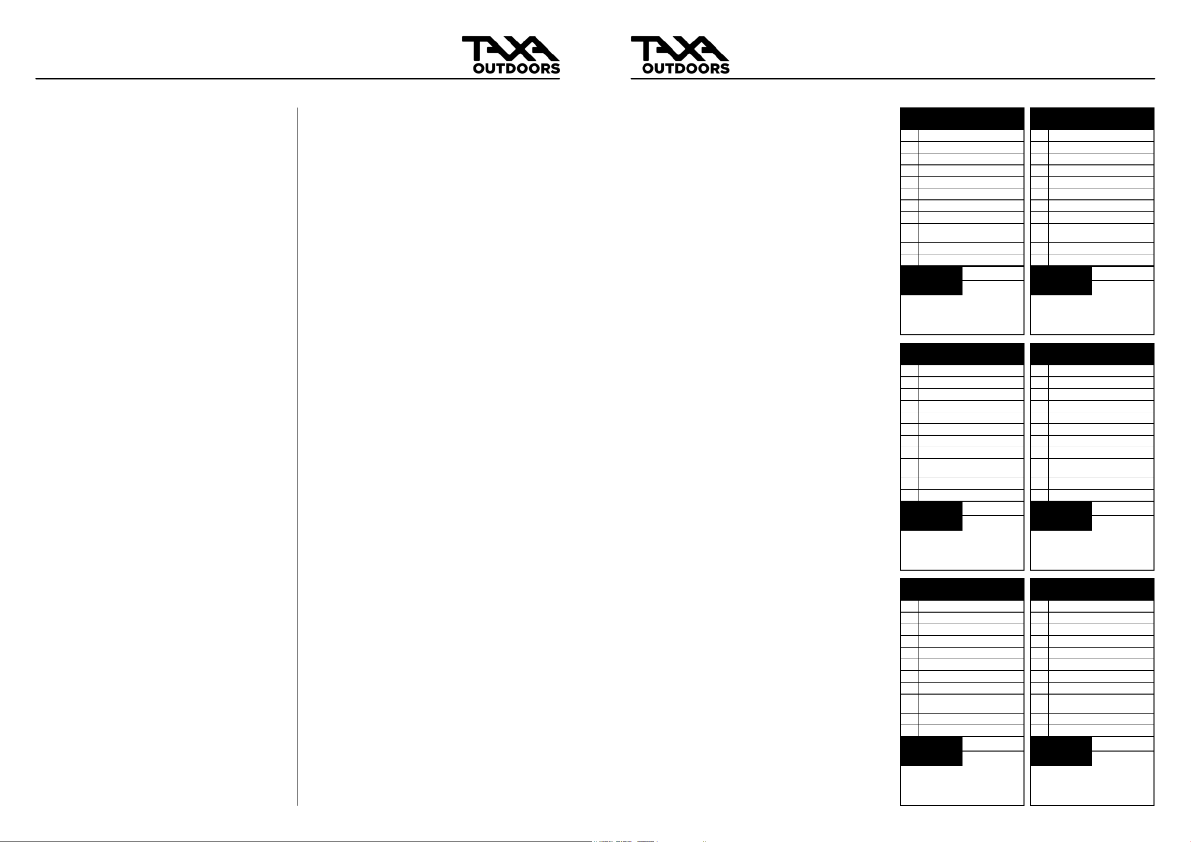
GENERAL CARE / MAINTENANCE GENERAL CARE / MAINTENANCE
MAINTENANCE
CHECKLIST
FRAME AND CHASSIS
HITCH COUPLERS
SAFETY CHAINS
JACK
TIRES AND WHEELS
BRAKE ADJUSTMENT
SEALANTS
TENT SIDES
CEILING, INTERIOR WALLS,
COUNTERTOP
FAUCETS AND FIXTURES
FABRIC AND UPHOLSTERY
DATE
NOTES
MAINTENANCE
CHECKLIST
FRAME AND CHASSIS
HITCH COUPLERS
SAFETY CHAINS
JACK
TIRES AND WHEELS
BRAKE ADJUSTMENT
SEALANTS
TENT SIDES
CEILING, INTERIOR WALLS,
COUNTERTOP
FAUCETS AND FIXTURES
FABRIC AND UPHOLSTERY
DATE
NOTES
MAINTENANCE
CHECKLIST
FRAME AND CHASSIS
HITCH COUPLERS
SAFETY CHAINS
JACK
TIRES AND WHEELS
BRAKE ADJUSTMENT
SEALANTS
TENT SIDES
CEILING, INTERIOR WALLS,
COUNTERTOP
FAUCETS AND FIXTURES
FABRIC AND UPHOLSTERY
DATE
NOTES
MAINTENANCE
CHECKLIST
FRAME AND CHASSIS
HITCH COUPLERS
SAFETY CHAINS
JACK
TIRES AND WHEELS
BRAKE ADJUSTMENT
SEALANTS
TENT SIDES
CEILING, INTERIOR WALLS,
COUNTERTOP
FAUCETS AND FIXTURES
FABRIC AND UPHOLSTERY
DATE
NOTES
MAINTENANCE
CHECKLIST
FRAME AND CHASSIS
HITCH COUPLERS
SAFETY CHAINS
JACK
TIRES AND WHEELS
BRAKE ADJUSTMENT
SEALANTS
TENT SIDES
CEILING, INTERIOR WALLS,
COUNTERTOP
FAUCETS AND FIXTURES
FABRIC AND UPHOLSTERY
DATE
NOTES
MAINTENANCE
CHECKLIST
FRAME AND CHASSIS
HITCH COUPLERS
SAFETY CHAINS
JACK
TIRES AND WHEELS
BRAKE ADJUSTMENT
SEALANTS
TENT SIDES
CEILING, INTERIOR WALLS,
COUNTERTOP
FAUCETS AND FIXTURES
FABRIC AND UPHOLSTERY
DATE
NOTES
Regular care & maintenance of your habitat is
important in furthering safety and dependability.
Keep good records of all service and maintenance
performed on your habitat. These records may
be necessary for limited warranty purposes
or may assist in future repairs. Always refer
to the manufacturers’ care and maintenance
recommendations for installed appliances.
Your habitat’s exterior is made of painted
aluminum composite panels, which are durable
and easy to maintain. Aluminum is lightweight
and relatively soft, naturally showing wear over
time. Cosmetic marks are intrinsic to aluminum
and do not constitute a fault in material or
defect in workmanship. Routine maintenance
is the best way to minimize and guard against
cosmetic changes due to weathering. Wash the
habitat exterior with a soft cloth, warm water and
soap thoroughly, paying special attention to the
graphics. Never use strong solvents or abrasives
when cleaning. Also, be aware that power buffers
and high pressure washers may damage or totally
remove the graphics.
See also the following summary of do’s and don’ts:
• Do use soft cloths to clean.
• Do be careful around graphics, washing
with the graphics, not against them.
• Do not use products containing ammonia
or caustic, harsh cleaning agents.
• Do not use high-pressure washers, rotating
brushes (i.e. in-car wash facilities), or
power buffers.
• Do not dry wipe surfaces.
• Do not use rubbing compounds.
FRAME AND CHASSIS
Over time, various weather and climate conditions
may lead to corrosion of your habitat frame and
chassis. Be sure to rinse the habitat undercarriage,
wheel wells, hitch and bumper of all dirt, oil, tar,
salt, and other debris periodically and as needed.
Remember to routinely inspect for evidence of
rust. Do so frequently when camping in or near
coastal regions.
HITCH COUPLERS
Inspect hitch couplers before each trip. Clean and
lubricate the ball socket and clamp monthly using
wheel bearing grease. If the hitch assembly and
coupler appears damaged in any way, contact
your dealer and resolve the problem before travel.
SAFETY CHAINS
Inspect safety chains before each trip. Replace
them before traveling if they are damaged or
compromised in any way.
JACK
Inspect and test the jack before each trip.
Clean and lightly apply oil periodically and
as needed. If your jack needs repair or other
service, see a qualied technician.
TIRES AND WHEELS
Inspect your habitat tires, checking air
pressure regularly and before each trip. Keep
them inated to recommended pressure,
which is located on the tire sidewall. Keep
a tire gauge in your tow vehicle or habitat.
Have the tires rotated by a qualied
technician at least every 5,000 miles.
BRAKE ADJUSTMENT
Have your habitat’s electric brakes adjusted
after the rst 200 miles. Have them tested
for brake drag every 3 months or 3000 miles,
whichever is earlier. When adjusting brakes
on any vehicle, either replace or adjust all
brakes at the same time, or at least both
brakes on the same axle. Qualied service
personnel should perform all required work
on brakes.
SEALANTS
Inspect all sealants/seals (i.e. doors, windows,
plumbing components, undercarriage) every
ninety (90) days, when the seasons change,
and before each trip. During your inspection,
look for cracks, voids, shrinkage, and any
other sign of deterioration. Replace sealant
where necessary, using the same type of
sealant. Contact your dealer or Taxa Inc.
for suggestions concerning replacement
sealants.
TENT SIDES
You may clean your habitat tent sides
periodically with warm soap and water and
then dry. The tent sides are made out of
waterproof, ame retardant, breathable,
ultra-violet treated, high-performance
material. While very durable, no fabric lasts
forever.

18 19
©2022 TAXA INC. v.4.2.010122 ©2022 TAXA INC. v.4.2.010122
HITCHING HITCHING
Our habitats require a 2” diameter hitch ball.
(Overland editions are outtted with a Lock And
Roll coupler).
Use of any other hitch ball diameter size will
create an extremely dangerous condition that
can result in separation of the coupler and ball,
and/or hitch ball failure. Other than this crucial
2” diameter requirement, there are numerous
habitat hitches and hitching components available
to you for your habitat. Be sure to consult your
tow vehicle manufacturer for hitch and/or hitch
assembly alternatives.
Pre-hitch/coupling/trip considerations and
inspection. Be sure your hitch and tow vehicle
are rated for the Gross Vehicle Weight Rating
(GVWR) of your habitat. Remember that the hitch
load rating must be equal to or greater than the
coupler load ( the hitch is attached to the car,
the coupler to the habitat). Be sure the hitch size
matches the coupler size.
Examine all hitch components before hitching,
looking for wear, corrosion, deformations,
stripping, and cracks. Replace worn, corroded
or cracked hitch components before coupling
the habitat to the tow vehicle. Be sure the hitch
components are tight and that the ball-locking
device works freely before coupling the habitat
to the tow vehicle. Remember to also Inspect
the safety chains. Be sure to correct any noted
problems or defects before towing the habitat.
Important Note: be sure to raise all habitat jacks
and close the habitat fully before driving off after
hitching. One of the most common mistakes is to
forget to raise a stabilizer jack and bending it.
Your habitat is equipped with a 7-pin connector,
which synchronizes the lights of your tow vehicle
and habitat. It can also connect their respective
braking systems. Your habitat is equipped with
electric brakes. Use of electric brakes are not
required in every state, however, we strongly
recommend that you use them.
WARNING: THE PROPER SELECTION AND
CONDITION OF THE COUPLER AND HITCH IS
ESSENTIAL TO THE SAFE TOWING OF YOUR
HABITAT. A LOSS OF COUPLING MAY RESULT IN
DEATH OR SERIOUS INJURY.
WARNING: AN IMPROPERLY COUPLED HABITAT
CAN RESULT IN DEATH OR SERIOUS INJURY.
WARNING: USE OF A TOW VEHICLE WITH A
TOWING CAPACITY LESS THAN THE LOAD
RATING OF THE HABITAT CAN RESULT IN
LOSS OF CONTROL, AND MAY LEAD TO
DEATH OR SERIOUS INJURY.
Hitching up your habitat will get easier with
practice. The hitching steps described below
are typical. However, we highly recommend that
you also consult the hitching and unhitching
instructions associated with your particular tow
vehicle and hitching conguration.
Typical hitching steps for 2” ball:
Hitching steps for Lock and Roll (Overland):
1. Crank the tongue of the habitat jack until the
hitch coupler is raised enough to clear the tow
vehicle;
2. Back the tow vehicle to the habitat until the
hitch ball or ‘pin’ is directly under the habitat
coupler. The use of a backing aid mirror may
be helpful, especially if you are hitching alone;
3. Set the parking brake of the tow vehicle;
4. Be sure the coupler latch-locking lever is fully
open, then lower the tongue jack until the ball
is rmly seated in the socket;
5. Close the coupler latch and secure it with a
locking pin or bolt (you can use the pin that
locks the caster wheel on to the front jack, the
Lock and Roll comes with a proprietary pin);
If you cannot get the latch to go down, try
pulling the tow vehicle forward, reversing a tiny
amount to create clearance, or release pressure
(this occurs usually when the habitat or tow
vehicle is on small slope or soft ground).
6. Securely attach the safety chains in a crossing
pattern to the tow vehicle and conrm that
they are properly connected to the habitat.
Do not fasten chains to any part of the hitch
unless the hitch has holes or loops designed
specically for that purpose, be sure the chains
do not drag during towing;
WARNING: IMPROPER RIGGING OF THE SAFETY
CHAINS CAN RESULT IN LOSS OF CONTROL OF
THE HABITAT AND TOW VEHICLE, LEADING TO
DEATH OR SERIOUS INJURY, IF THE HABITAT
UNCOUPLES FROM THE TOW VEHICLE.
7. The electric brakes need to be controlled with
a proportional brake controller. Some tow
vehicles have these pre-integrated. There are
wired and wireless versions available online, at
towing centers, etc.
8. Connect the breakaway switch. Attach and
secure the breakaway switch cable to the tow
vehicle bumper or frame independently of the
safety chains. The following are guidelines for
attaching the cable:
• The cable should come straight out from
the switch to attach to the tow vehicle
• The switch and cable should be located
and secured on the same side of the
habitat and tow vehicle
• Do not loop the cable over the hitch
ball; the cable may bounce off while the
vehicle is moving
• Before towing you may test the
breakaway assembly by pulling the pin
out of the switch to conrm activation
of the habitat electric brakes. See also
the diagram/depiction in the “Towing”
section.
(Continued on next page)

20 21
©2022 TAXA INC. v.4.2.010122 ©2022 TAXA INC. v.4.2.010122
HITCHING LOADING & TOWING
(Continued)
WARNING: DO NOT CONNECT THE
BREAKAWAY SWITCH LANYARD TO THE HITCH
BALL OR ANY PART OF THE HITCH ASSEMBLY.
NOTE: Your breakaway switch will automatically
engage the electric habitat brakes if the safety
chains fail during uncoupling.
9. Connect the power cord between the tow
vehicle and the habitat, leaving enough
slack for the tow vehicle to turn without
disconnecting the power cord;
10. Adjust side mirrors;
11. Check all lights on habitat and tow vehicle,
ensuring that they are working properly.
12. Conrm the brakes are working properly prior
to towing the habitat on a public road. You
can, for example, check the operation of the
habitat brakes by pulling forward and using
the AUTOWBRAKE fob or hand control of any
alternate brake controller.
Depending on your tow vehicle or intended usage
of the habitat, you may want to consider the use
of a weight distributing hitch and/or sway bars.
These distribute the tongue weight of the habitat
further away from the rear and can help in vehicle
handling.
WARNING: FOLLOW ALL INSTRUCTIONS
PROVIDED BY YOUR TOW VEHICLE’S TOW
PACKAGE MANUFACTURER AND/OR INSTALLER
WEIGHTS AND SPECIFICATIONS
Weights and measurements are crucial to
understand and take into consideration, both
for your safety and for your enjoyment as
a habitat owner. Please study and learn the
following weight ratings and reference them
before loading or towing.
Mantis Overland
Cricket
Cricket Overland
TigerMoth
TigerMoth Overland
WoollyBear
GVWR 4,200
Mantis
5,000 2,700 3,000 2,200 2,400 2,100
GAWR 4,000 5,200 3,500 3,500 2,000 2,200 2,000
UVW (Dry Weight) 2,972 3,486 1,753 1,978 1,310 1,458 1,270
CCC (Cargo Capacity) 1,028 1,614 900 1,022 990 942 830
Tongue Weight 435 510 245 264 127 195 140
Bunk Weight Rating 185 185 130 130 N/A N/A N/A
Exterior Length 19' 19' 15' 15' 12'10" 12'9" 10'8"
Exterior Height (open) 9'10" 10'1" 9' 9'4" N/A N/A N/A
Exterior Height (closed) 6'9" 7' 6'11" 7'2" 6'8" 7' 4'9"
Ground Clearance 11" 14" 11" 14" 15" 18" 12"
NOTE: All measurements are in Pounds (Lbs)
unless otherwise noted.
A. 2” ball coupler
B. Habitat wiring plugged securely into
tow vehicle, lights tested.
C. Chains crossed and securely attached
to frame of hitch.
D. Breakaway switch cable attached to
tow vehicle separate from chains
Coupler Securely Latched and Pinned
B
A
C
D
Example of Weight Distributing Hitch Assembly
The process of safely and properly loading your
habitat should become easier with practice and
experience. Please rst get familiar with and
understand the following terms related to your
habitat’s weight, carrying capacity, and rating.
Refer to our spec sheet for more information.
TERMS
Gross vehicle weight rating (GVWR) is the
maximum permissible weight of the habitat when
fully loaded and equipped/outtted. It includes but
is not limited to all weight at the habitat axle(s) and
tongue or pin as well as all add-ons, appliances,
accessories, potable water, etc. This number is
recorded on the permanent label on the tongue of
your habitat.
Dry weight or unloaded vehicle weight (UVW)
is the weight of the habitat as manufactured at
the factory (typical weight without loading, no
options). It includes all weight at the habitat axle(s)
and tongue or pin.
You will need to account for the weight of the
dealer or third-party installed add-ons, options
and accessories, if any, in determining your actual
UVW. In sum, your actual UVW will vary (and
increase) to the extent you have outtted your
habitat with additional items. Note: Your cargo
carrying capacity (discussed below) will vary (and
decrease) to the extent of the weight of dealer
or third-party installed add-ons, options and
accessories, if any.
Cargo carrying capacity (CCC) is equal to GVWR
minus UVW and potable water weight.
However, remember that your actual CCC will vary
(and decrease) to the extent you have outtted
your habitat with additional items. Please refer to
the stickers located at the front exterior of your
habitat for CCC.
Gross axle weight rating (GAWR) is the value
specied as the load carrying capacity of a single
axle system, as measured at the tire-ground
interfaces. Please refer to the sticker located at the
front exterior of your habitat for GAWR.
Gross trailer (habitat) weight (GTW) is the weight
of the habitat with all the items and supplies that
are loaded into the unit at any point in time and
must be less than the allowed GVWR.
GENERAL WEIGHT CONSIDERATIONS
Before towing, you must choose the items you will
load onto your habitat and then determine whether
the loaded weight is safe and proper.
Of course, the best way (highly recommended) to
calculate the loaded weight of your habitat is to
have it weighed while loaded, and then compare
it with the GVWR. Otherwise, you will need to do
some calculations on your own in order to make
an appropriate determination. If the loaded weight
of your habitat exceeds the GVWR, your habitat
is overloaded and should not be towed. You will
need to remove items from, and reduce the loaded
weight of, the habitat until it’s at or below the
GVWR before towing. Note: remember to include
in your calculations the weight of dealer or third-
party installed equipment, options, add-ons,
accessories and any other non-standard items. As
an additional safety precaution, we recommend
that you take a conservative approach when doing
your own weight calculations.
WEIGHT/LOAD DISTRIBUTION AND TONGUE
WEIGHT
Proper weight and load distribution is essential to
safe towing. Load the habitat evenly (front to back
and side to side) and securely, keeping heavier
items as low as possible. Be sure to secure the load.
A rmly secured load will be less prone to shifting
and should help maintain load balance during
travel.
The tongue is the habitat arm extension that
couples with the tow vehicle receiver.
Tongue weight is the amount of weight borne
by the habitat hitch and another important
consideration when loading your habitat.
Generally, the actual tongue weight should equal
approximately 10-15% of the gross habitat weight.
Excessive tongue weight will make your tow
vehicle’s steering and braking less responsive.
Insufcient tongue weight may cause your habitat
to sway.
You could weigh your loaded habitat’s tongue to
determine the actual tongue weight. However,
you may also observe the actual tongue weight
and determine if it is too light or too heavy. For
example, a habitat with a proper tongue weight
will form a straight line from front to back between
the tow vehicle and the habitat. A habitat with the
weight improperly distributed (i.e. a light tongue
weight) will cause the coupling between the tow
vehicle and habitat to rise, with the weight pressing
down at the rear of the habitat and the front of the
tow vehicle. Excessive tongue weight will do just
the opposite.

22 23
©2022 TAXA INC. v.4.2.010122 ©2022 TAXA INC. v.4.2.010122
If you notice a rise or fall in your tow coupling, you
will need to redistribute the weight of the load
before getting on the road. If you have trouble
estimating the combined weight of your habitat
plus cargo, take your loaded habitat to a vehicle
scale at a nearby weigh station or truck stop.
Important Note: you need to also refer to your tow
vehicle’s towing capacity and other towing and
load capacity-related definitions and instructions
before getting on the road. Please also consult
your supplying dealer or Taxa Inc. if you have any
questions regarding these terms and/or loading
your habitat.
Example of Poor Weight Distribution
TOWING
We want your towing experiences and practices to
be safe and enjoyable. Please take your time, and
give special attention to all safety matters prior to
and during the towing of your habitat.
As previously indicated, we recommend that
you practice towing your habitat in, for example,
an empty parking lot before going on your rst
camping trip. This initial trial and practice is fun
and will help you get accustomed to and familiar
with your habitat’s systems and operation.
Please also make note of any questions, issues or
problems that arise during your pre-travel towing
practice, and inquire with your dealer or email us
customerservice@taxaoutdoors.com. You can also
visit our website (www.taxaoutdoors.com) for
more contact information. Please also refer to the
“Overview of Safety Precautions’’ and “Pre-Travel
Checklist” sections before towing your habitat.
SAFETY CHAINS
We have equipped your habitat with safety chains.
Make use of them. Safety chains serve to maintain
the connection between your habitat and the
tow vehicle in the event of separation of the ball
and habitat coupling. Be sure to hook the safety
chains to the frame of the tow vehicle (not the
hitch), crossing them under the habitat’s tongue.
Also, remember to inspect the length of the chains
once they are attached to the tow vehicle frame.
A proper chain length will allow turns and prevent
the chains from dragging on the road.
BREAKAWAY SWITCH
Your habitat is equipped with a breakaway switch.
For every Mantis the breakaway switch is wired to
the Mantis’s internal battery. Breakaway switches
are designed to activate the electric brakes in the
event your habitat disconnects/uncouples from
the tow vehicle. Your habitat battery powers this
braking. Ideally, the safety chains will prevent your
habitat from disconnecting if the coupler comes
off the hitch ball. However, if the safety chains fail,
the breakaway pulls the pin out of the switch which
res the brakes and serves as a last line of defense
against a runaway habitat. The breakaway switch
cable needs to be secured to the tow vehicle
bumper or frame independently of the habitat
safety chains. The following are guidelines for
attaching the cable:
• The cable should come straight out from
the switch to attach to the tow vehicle.
• The switch and cable should be located
and secured on the same side of the
habitat and tow vehicle.
• Do not loop the cable over the hitch
ball; the cable may bounce off while the
vehicle is moving.
• Before towing, you may test the
breakaway by pulling the pin out of
the switch to conrm activation of the
habitat electric brakes.
LOADING & TOWINGLOADING & TOWING
TIRE PRESSURE
You are responsible for maintaining proper tire
pressure in the tires of your habitat and tow
vehicle. Thus, always check your tire pressure
and refer to the “Tires” discussion herein before
traveling.
BRAKES
You are responsible for inspecting and maintaining
both your habitat and tow vehicle brakes before
towing. Do not tow your habitat unless you have
conrmed your brakes are in good condition and
operating properly. Be sure to have a qualied
technician perform all brake adjustments, service
and maintenance. Please also refer to the “Brakes”
discussion herein before traveling.
LIGHTS
Be sure to check all electrical connections to
ensure all lights on the tow vehicle and habitat
are functioning properly before traveling. The
brake lights, hazard, and turn signals should be in
synchronization with the tow vehicle.
LEVELING
The habitat and tow vehicle must be level when
hitched. Risers and drops are available to match
the tow vehicle’s hitch height with the habitat’s.
Dragging may occur if the hitch is too low.
Conversely, if the hitch is too high, the rear of the
habitat is exposed to striking higher points in the
road.
GENERAL TOWING/DRIVING
Drive defensively, anticipating stops, braking
early, and never following closely. We recommend
maintaining a length of at least three cars and a
habitat (approximately 65 ft.) between you and
the car in front of you for every 10 mph of speed
you are traveling (for example, at 60mph, you
should maintain approximately 390 ft. of distance
between your vehicle and the vehicle in front of
you). This should give you adequate time to safely
complete a proper avoidance maneuver (i.e. come
to a safe stop, change lanes, etc.) in the event of,
for example, an abrupt stop or emergency.
Longer stopping distances are required when
towing a habitat, so remember to start braking
sooner than you would if driving without your
habitat. Begin slowing down well in advance of
anticipated street/road dips and depressions.
It also takes longer to accelerate when towing
a habitat. Thus, remember to account for both
the slower acceleration rate and the combined
length of your tow vehicle and habitat when
passing another vehicle and then safely returning
to your lane. In sum, always pass, allow others to
pass, and change lanes with care. We also do not
recommend using cruise control or overdrive when
towing/traveling.
SWAYING AND FISHTAILING
Excessive sway or shtailing of your habitat can
lead to the rollover of the habitat and tow vehicle,
and thus, serious injury or death. The tendency for
the vehicle to sway increases with speed. Thus,
reduce speed as needed and in inclement or harsh
weather conditions (i.e. high winds, rainstorms,
slippery roads, etc.). The following paragraphs
outline methods of reducing sway or shtailing, but
are not exhaustive.
GRADUAL BRAKING
Do not jam/slam on the brakes or press on the
accelerator, both of which may make the situation
worse and result in severe injury or death. Instead,
remove your foot from the accelerator and reduce
your speed gradually whenever possible.
MINIMIZE QUICK STEERING MOVEMENTS
Quick steering movements will actually cause
increased sway and loss of control. Keep both
hands on the wheel, and hold the wheel as straight
as possible until stability is regained; and
As soon as practical after regaining control,
pull over and check tire pressures, cargo weight
distribution, and inspect the habitat and tow
vehicle for any signs of failure or defect. If you
suspect a mechanical failure, we recommend that
you not tow until the problem is identied and
remedied. If you choose to travel, do so at reduced
speeds and with heightened caution until the
problem can be identied and remedied.
WARNING: Side to side motion (sway) that
begins as you reach a certain speed will likely
become whipping at higher speeds. As soon as
you notice sway, slow your vehicle by letting
off the accelerator pedal. Then stop to check
the habitat and tow vehicle as soon as it is safe
to do so. Sway can sometimes be temporarily
controlled by pressing the brake controller’s
brake button independent of touching the tow
vehicle’s brake. This tends to pull the habitat
back in line and gives greater control as one
determines the issue at hand.
A. Switch location
B. Cable attached independently to tow
vehicle, with pin secured in switch
Breakaway Switch Installed
B
A

24 25
©2022 TAXA INC. v.4.2.010122 ©2022 TAXA INC. v.4.2.010122
Your habitat is equipped with electric brakes and
a wireless proportional brake controller. Under
normal driving/towing conditions, the habitat
brakes will operate only in conjunction with a
properly installed brake controller (which is also
discussed below). Please also obtain and read the
separate manual of the brake controller.
NOTE: in an emergency uncoupling of your tow
vehicle and habitat, your habitat electric brakes
will automatically engage even without a brake
controller. This assumes, of course, that you have
properly attached and secured the provided
breakaway switch. See also “Hitching” and
“Towing” sections herein.
BREAKING-IN BRAKES
We recommend that you break-in your habitat
brakes in an empty, paved parking lot, not on a
public road, when practicable. To break-in your
brakes, apply the brakes at least twenty (20)
times, decreasing your speed approximately 20
mph in each application. Allow a few minutes for
the brakes to cool between each application so
that the brake shoes and magnets “wear-in” to the
drum surfaces.
BRAKE CONTROLLER
When a brake control or controller is properly
installed, your habitat electric brakes will work in
synchronization with your tow vehicle brakes. If
you sense lock-up, “grabbiness,” or your habitat
“jerking” or “pushing” the tow vehicle when
braking, your braking systems are not properly
synchronized. You may need to have small
adjustments made periodically because of, for
example, changing loads and driving conditions.
Brake Controllers are proportionally adjustable and
small adjustments are easily made. Important Note:
Your habitat does not include a brake controller
from the factory. Refer to your brake controller
manual for instructions on synchronization, use,
maintenance, and adjustments.
WARNING: MINIMUM VEHICLE STOPPING
DISTANCES ARE ACHIEVED WHEN WHEELS
APPROACH LOCK UP. BRAKE LOCK UP SHOULD
BE AVOIDED AS IT RESULTS IN POOR VEHICLE
STABILITY AND CONTROL.
CONNECTOR
Your provided 7-pin cord connector located at
the front of the habitat transfers electrical power
from the tow vehicle battery to the habitat brakes,
lighting system, and battery.
BRAKING TIPS
Do NOT use the habitat brakes only. They were
designed to provide braking for your habitat, not
the tow vehicle. Remember that the added weight
of both the habitat itself and the cargo you are
carrying can put additional load pressures on
your tow vehicle brakes. It also may, under some
conditions (i.e. slippery pavement, loose gravel,
etc.), impact overall stability and control of your
tow vehicle and habitat. Thus, be sure that you
have all the information you need to make an
informed decision regarding your brakes before
getting on the road.
BRAKE ADJUSTMENTS
Generally, brakes should be adjusted after the rst
200 miles, every 3,000 miles thereafter, and/or as
use and performance requires. We recommend that
you have a qualied technician perform all brake
adjustments, service and maintenance.
TIRESBRAKES
OVERVIEW
Properly-maintained tires improve the steering,
stopping, traction, and load-carrying capability
of your vehicle. Under-inated tires and
overloaded vehicles are a major cause of tire
failure. Maintaining proper tire pressure, tire and
vehicle load limits, avoiding road hazards, and
regularly inspecting tires for cuts, slashes, and
other irregularities are important steps in avoiding
tire failure, such as tread separation, blowout,
or at tires. These steps, along with other care
and maintenance activities, may improve vehicle
handling, help protect you and others from
avoidable breakdowns and accidents, improve fuel
economy, and increase the life of your tires. In sum,
you are responsible for making tire safety a regular
part of your tow vehicle and habitat maintenance
routine. Remember that the time you spend is
minimal compared with the inconvenience and
safety consequences of tire failure.
FUNDAMENTALS
Federal law requires tire manufacturers to place
standardized information on the sidewall of all
tires. This information identies and describes the
fundamental characteristics of the tire and also
provides a tire identication number for safety
standard certication and recall matters.
Sidewall markings and important terms … your
habitat tires should be marked with either a
designation of “ST” (i.e. ST235/75/ R15, or
LT235/75/R15). The “ST” indicates Standard
Habitat Service and is designed for habitat use
only. The “LT” indicates Light Truck Service and is
designed to be used on vehicles that are capable
of carrying heavy cargo.
TERMS
Maximum Load Rating is the maximum load in
kilograms and pounds that each tire can carry.
Maximum Permissible Ination Pressure is the
greatest amount of air pressure that should be put
in the tire under normal driving conditions.
Maximum Load Single kg (lbs) at kPa (psi) cold
Indicates the maximum load and tire pressure
when the tire is used as a single.
LOAD RANGE
Identies the tire’s load-carrying capabilities and
its ination limits.
TIRE TREAD
The tire tread provides the gripping action and
traction that helps prevent your vehicle from
slipping or sliding, especially when the road is wet
or icy. Generally, tires are not safe and should be
replaced when the tread is worn down to 1/16 of
an inch. The following chart is a general guide for
determining the condition of and maintenance
action for your habitat tires:
REPLACEMENT
Please refer to the tire sidewall on your habitat’s
standard tires for information regarding proper
tire replacement. Be sure to replace your standard
habitat tires with “ST” or “LT”designated tires.
Note: replacing your habitat tires with non-ST
designated tires will void the Limited Warranty.
See Limited Warranty section herein. If you have
any doubt about the correct size/type to choose,
consult with a tire dealer. Please also refer to the
manual provided by your specic tire manufacturer
for care and use instructions.
REPAIR
The proper repair of a punctured tire requires a
plug for the hole and a patch for the area inside the
tire that surrounds the puncture hole. Punctures
through the tread may be repaired if they are not
too large, but punctures to the sidewall should NOT
be repaired. Tires must be removed from the rim to
be properly inspected before being plugged and
patched.
WARNING: ALL TIRE REPAIRS SHOULD BE
PERFORMED BY A QUALIFIED TECHNICIAN.
TIRE PRESSURE AND LOAD LIMITS
Tire ination pressure is the level of air in the tire
that provides it with load-carrying capacity and
affects the overall performance of the vehicle.
Because tires may naturally lose air over time,
or when driven over objects such as potholes
or curbs, it is important to check tire pressure
monthly and before every trip. The tire ination
pressure number indicates the amount of air
pressure– measured in pounds per square inch
(psi)– a tire requires to be properly inated. Vehicle
manufacturers determine this number based on
the vehicle’s design load limit, that is, the greatest
amount of weight a vehicle can safely carry and
the vehicle’s tire size. Excessive loads may lead to
abnormal tire ex, tire overheating, and ultimately,
tire failure.
(Continued on next page)

26 27
©2022 TAXA INC. v.4.2.010122 ©2022 TAXA INC. v.4.2.010122
Excessive loads may lead to abnormal tire ex, tire
overheating, and ultimately, tire failure. As travel
habitats may be set up and loaded in varying
ways, proper air pressure should be determined
by referencing the information on your tire. Please
also refer to the Tire and Loading Information
sticker located at the front exterior of your habitat.
The proper tire pressure for your vehicle is referred
to as the “recommended cold ination pressure.”
Proper pressure depends on many conditions:
terrain, temperatures, altitude, etc. A “cold” tire in
this sense is one that has not been driven on for at
least three hours. When you drive, your tires get
warmer, causing the air pressure within them to
increase. Therefore, to get an accurate tire pressure
reading, you must measure tire pressure when the
tires are cold or account for the extra pressure in
warm tires.
WARNING: IMPROPER TIRE PRESSURE CAN
QUICKLY LEAD TO EXCESSIVE WEAR AND
DANGEROUS SITUATIONS.
Diagnosing Tire Ination Level
TIRE PRESSURE STEPS
1. Locate the recommended tire pressure
on the vehicle’s tire.
2. Record the tire pressure of all tires.
3. If the tire pressure is too high in any of
the tires, slowly release air by gently
pressing on the tire valve stem with the
edge of your tire gauge until you get to
the correct pressure.
4. If the tire pressure is too low, note the
difference between the measured tire
pressure and the correct tire pressure.
These “missing” pounds of pressure are
what you will need to add.
5. At a service station, add the missing
pounds of air pressure to each tire that
is under-inated.
6. Check all the tires to make sure they
have the same air pressure (except in
cases in which the front and rear tires
are supposed to have different amounts
of pressure).
IMPORTANT REMINDERS
• Do not exceed the maximum
recommended pressure.
• The air pressure recommended on
the tire information placard is for the
original standard equipment tires only.
Your habitat may be equipped with
optional-sized tires. Always follow the
pressure recommendations stamped
in the tire sidewall for any replacement
tire.
• Rotate tires every 5,000 miles or as
recommended by the tire manufacturer
TIRE SAFETY CHECKLIST
1. Check tire pressure regularly (at least
once a month and before any extended
trip/traveling), including the spare
tires, if any… Note: When checking air
pressure, be sure that all tires have both
the correct and identical pressure before
getting on the road;
2. Check and torque wheel lug nuts
regularly;
3. Inspect tires for cuts, slashes, punctures
and other irregularities at least on
a monthly basis and before every
extended trip/traveling;
4. Remove any foreign objects (i.e. pieces
of glass or metal, etc.) wedged in the
tread;
5. Conrm all tire valves have valve caps;
6. Do not overload your tow vehicle or
habitat;
7. Slow down when having to go over a
pothole or other object in the road,
and avoid running over curbs and other
foreign objects in the road and when
parking if you can safely do so;
8. Replace tires when tread depth
approaches and/or reaches 1/16 of an
inch;
9. Have a qualied technician perform tire
service, maintenance and adjustments
as needed.
WHEELSTIRES
WHEEL NUT TORQUE
Proper wheel nut torque is essential to safe towing.
The wheel and axle systems used in habitats are
similar in many ways to those found in motor
vehicles. However, they differ in several important
ways. First, habitat wheels do not steer, and are
subjected to high side load stress when making
tight turns around corners. This tends to ex the
wheel and may loosen the wheel nuts. Wheel nut
torque requirements vary depending on the size
and manufacturer of the wheel.
WHEEL NUT TORQUE ADJUSTMENT
Setting torque value on a dial indicator wrench:
1. Make sure your indicator needle is set to
“0”.
2. As you apply clockwise pressure to the
wheel nut, both needles will show the
current amount of torque being applied.
3. When you reach your desired torque
value, stop applying pressure and your
indicator needle will stay at the highest
torque value reached.
Setting torque value of adjustable dial wrench:
1. Unlock the handle and set the dial to
your desired torque value.
2. Lock the handle back in place.
3. As you apply clockwise pressure to the
lug nut, you will hear an audible “click”
when the desired torque wrench value is
reached.
4. Do not apply further pressure once you
hear the “click”.
PRE-TRIP TORQUING PROCEDURE
Be sure to tighten the wheel nuts and torque to
90 ft/lbs. Follow the torque sequence and torque
table provided next:
Wheel Nut Torquing Table
1st Stage 20-25 ft./lb.
2nd Stage 55-60 ft./lb.
3rd Stage 85-90 ft./lb.
Stage 1: Set your torque wrench to the 1st stage
value on the Wheel Nut Torque Table. Begin with
the appropriate bolt for your wheel (12 o’clock
position for 8 and 6 hole wheels and 2 o’clock
position for 5 hole wheels) and apply torque to
all wheel nuts following the star pattern as shown
in the Wheel Nut Torquing Sequence illustration
shown here.
Stage 2: Increase your torque wrench setting to
the 2nd Stage value on the Wheel Nut Torque
Table. Begin with the appropriate bolt for your
wheel and apply torque to all wheel nuts following
the star pattern. Following stage 2, the wheel can
support the weight of the habitat and may be
lowered off of the jack stands.
Stage 3: Increase your torque wrench setting to
Final Torque value on the Wheel Nut Torque Table.
Begin with the appropriate bolt for your wheel and
apply torque to all wheel nuts following the star
pattern.
Follow-up: If the wheel was replaced, check the
torque again at every 50 miles for the rst 500
miles and prior to each trip thereafter.
If you notice a wheel wobbling or hear a rattling
sound coming from a wheel, especially at low
speeds, a wheel lug may have come loose. This
problem is usually caused by improper tightening
or by faulty or damaged lug bolt threads. If you
have reason to believe a lug nut has come loose,
safely stop the vehicle at the side of the road as
soon as possible. Put up warning devices. Remove
the lug caps and check the tightness of all the lug
nuts. If lug bolt threads are damaged or faulty, get
professional services help.
WARNING: DO NOT TOW THE HABITAT WITH
MISSING LUG NUTS OR FAULTY LUG BOLTS.
BALANCING, ALIGNMENT AND LUBRICATION
To avoid vibration or shaking of the vehicle when
a tire rotates, the tire must be properly balanced.
This balance is achieved by positioning weights
on the wheel to counterbalance heavy spots on
the wheel-and-tire assembly. A wheel alignment
adjusts the angles of the wheels so that they are
positioned correctly relative to the vehicle’s frame.
This adjustment maximizes the life of your tires.
These adjustments require special equipment and
should be performed by a qualied technician.
Wheel bearings should be repacked every 6000
miles or every 6 months. Every time the wheel hub
is removed, the wheel bearings must be adjusted.
Please refer to manufacturer instructions or
schedule maintenance with a qualied technician
to repack wheel bearings.

28 29
©2022 TAXA INC. v.4.2.010122 ©2022 TAXA INC. v.4.2.010122
SITE SELECTION
With time and experience, you will get better
at spotting and identifying good camping sites.
Although they will vary to some degree, all good
sites will be close to level and have a rm, not soft,
ground that will support the weight of jacks and/or
other support devices. There are also many public
camping sites that provide electrical and other
useful hook-ups or services.
Once you have chosen your site, refer to the
following important sections which will prepare
your habitat for your adventure.
LEVELING AND STABILIZING
The following steps should be followed in order to
ensure that your habitat is level and stable. These
steps should be completed in entirety before
proceeding with any setup steps.
1. Before uncoupling, level the unit from
side to side if desired with wood or
plastic leveling blocks. Place the blocks
on the ground forward of the wheels
and tow the unit onto the blocks
2. Lower the jack onto blocks or pad, if
necessary
3. Use a smartphone level to ensure
habitat is level
4. Once the unit is level, use wheel chocks
or blocks to prevent the habitat from
moving
5. Uncouple the habitat from the tow
vehicle, unplug 7 pin connector from
vehicle
6. Lower the stabilizing jacks until they
rmly engage. Be sure all jacks have
about the same pressure on them
NOTE: Before resuming travel, be sure that the
stabilizer jacks are fully retracted/raised and that
the habitat has been fully closed.
WARNING: DO NOT ATTEMPT TO USE JACK
STANDS OR STABILIZER JACKS TO JACK UP
THE HABITAT OR SUPPORT THE FULL WEIGHT
OF THE HABITAT. DO NOT ATTEMPT TO LEVEL,
RAISE, OR OTHERWISE PLACE ALL OF THE
WEIGHT OF THE HABITAT ON THE STABILIZER
JACKS. STABILIZER JACKS ARE NOT DESIGNED
TO BEAR WEIGHT.
WARNING: DO NOT ATTEMPT TO USE THIS JACK
TO LIFT EXCESSIVE WEIGHT OR TIRES OFF
OF THE GROUND. VEHICLE FRAME AND DOOR
JAMB DAMAGE MAY OCCUR. USE ONLY STOCK
HANDLE SUPPLIED. DO NOT USE A CHEATER
BAR ON HANDLE. DO NOT USE THIS JACK AS A
TIRE CHANGING JACK.
HABITAT SETUP
1. Ensure that the habitat is level.
2. Open roof (see below for more
information)
3. Connect to shore power, if available
4. Connect to site water supply, if available
5. Set up the remaining features and/or
options as needed
For instructions on setting up your roof, please see
the manuals that correspond with your specic
habitat.
VENTILATION
Good ventilation and indoor air quality is essential
to long-term enjoyment of your habitat. Inadequate
ventilation can increase indoor pollutant levels. To
maintain good air quality, be attentive to proper
ventilation of your habitat, keep it clean, and
prevent and avoid unnecessary air pollutants.
Common indoor air pollution sources include
molds, pollen, pet fur dander, secondhand smoke,
carbon monoxide from burning propane and other
fuels, and household cleaners.
Travel habitats are much smaller than homes.
Thus, the exchange of air inside a travel habitat is
signicantly less than a home. Proper ventilation
is an ongoing process, occurring before, during,
and after use, and at times when the temperatures
and humidity are elevated. Decreasing the ow
of air by sealing the travel habitat may increase
the presence and/or concentration of indoor air
pollutants, such as but not limited to, molds and
household chemicals. Improve ventilation by
opening windows, using fans and opening vents,
running the air conditioner, or some combination
thereof. We also recommend that you do not
smoke or use any type of bug or other chemical
spray inside your habitat.
WARNING: YOUR HABITAT WAS DESIGNED
FOR RECREATIONAL USE AND SHORT-TERM
OCCUPANCY ONLY. LONG-TERM OCCUPANCY
CAN CREATE CONDITIONS, WHICH IF NOT
MANAGED PROPERLY, CAN BE HAZARDOUS
TO YOUR HEALTH AND CAUSE SIGNIFICANT
DAMAGE TO YOUR HABITAT.
VENTILATION & MOISTURESITE SELECTION & SETUP
The following are three (3) basic strategies
recommended by the Environmental Protection
Agency (EPA) to improve indoor air quality:
1. Remove Sources Eliminate sources of
pollution and/or reduce their emissions.
Pollutants that this strategy can have
an impact upon are: (i) Biological
Contaminants such as bacteria, molds,
mildew, viruses, animal dander, and
pollen, (ii) Household Products such
as paints, varnishes, cleaning and
disinfecting solutions, cosmetics and
hobby products, and (iii) Pesticides.
2. Ventilation Increase the amount of
outdoor air coming indoors. Typically,
habitat air conditioners, for example, do
not mechanically bring fresh air into the
unit. Simultaneously opening doors and
windows to allow fresh air in along with
turning on fans to take inside air out is
an effective way to improve ventilation.
Remember, if there is insufcient
outdoor air entering a habitat, pollutants
may accumulate to higher levels.
3. Air Cleaners Air cleaners are designed
to remove particles from the air. There
are many types and sizes of air cleaners
available to you on the market. Note:
Air cleaners are not generally designed
to remove gaseous pollutants. The
effectiveness of an air cleaner depends
on how well it collects pollutants
from indoor air and how much air it
draws through the cleaning or ltering
element. For more information about
ventilation, indoor air quality and its
effects, please refer to www.epa.gov/
iaq.
MOISTURE/CONDENSATION
The relatively small volume and compact
construction of travel habitats means that the
normal activities of even a few persons can lead
to rapid, visible moisture saturation in the habitat,
especially in cold weather. Note: some estimates
indicate that a family of four can vaporize up to
three gallons of water through daily breathing,
cooking, bathing and washing. Just as the moisture
collects on the outside of a glass of cold water
during humid weather, moisture will condense
on the inside surfaces of the habitat during cold
weather when the relative humidity of the inside
air is high. Unless water vapor is carried outside,
it will condense on the inside of the windows and
walls. Thus, when you observe signs of excessive
moisture and condensation in the habitat, take
action to minimize the effects. Such action steps in
non-extreme hot or cold weather conditions may
include, but not be limited to, the following: Allow
excess moisture to escape by ventilating with
outside air. Open windows to provide circulation of
outside, drier air to the inside. While this ventilation
may increase the heating load during cold weather,
it will greatly reduce water condensation.
Minimize moisture released inside the habitat such
as steam from excessive boiling water or other use
of hot water. Remove water or snow from shoes
before entering the habitat. Avoid drying wet or
damp clothing, towels, gear and other items inside
the habitat.
Manage the inside temperature during cold
weather. Remember that the higher the
temperature inside (in cold weather) will cause
condensation to form on areas that are not
insulated as well as others (windows, vents, wall
studs, etc.); try to avoid drastic, quick temperature
reductions, which can increase moisture
condensation inside.
Properly maintain and secure the exterior of the
habitat. This will help keep a tight barrier against
water intrusion.
NOTE: Using your habitat in severe climates or
weather conditions such as extreme hot, humid
or cold weather, which is NOT recommended (see
“severe weather use” section), will require extra
care, attention and maintenance of moisture-
related issues and relative humidity conditions
inside the habitat.

30 31
©2022 TAXA INC. v.4.2.010122 ©2022 TAXA INC. v.4.2.010122
Your habitat’s electrical system is primarily a 12
Volt Direct Current (DC) system and has 120V AC
outlets that operate only when attached to shore
power.
12V DC OVERVIEW
Your habitat 12 Volt system is powered by a 12V
battery or batteries (see “Battery” section). All
installed appliances, aside from air conditioning,
operate fully with 12V power. Fuses for 12V circuits
are located either below the switch itself or behind
the plastic panel of the Auto-Detect WFCO Power
Center at the bottom of your kitchen cabinet.
7-PIN CONNECTOR
Use your 7-pin connector plug to connect your tow
vehicle and habitat electrical systems. This cord
is located at the front of your habitat and plugs
into a receptacle provided in your tow vehicle’s
hitch package. In addition to charging your habitat
battery while driving, this connection powers your
habitat lights and electric brakes.
WARNING: BE SURE TO PLUG THE 7 PIN
CONNECTOR WITH THE PROPER HOLES AT TOP
AND BOTTOM. FAILURE TO DO SO MAY DAMAGE
YOUR HABITAT WIRING AND ELECTRIC BRAKE
SYSTEM.
7-Pin Connector Detail
NOTE: We recommend disconnecting the 7 pin
connector from the tow vehicle when camping!
When hitching and unhitching, be sure to move the
7-pin connector cord so it does not get damaged
by, for example, the hitch and/or pin box. Do not
allow the cord to drag on the ground and store in
the provided receptacle when not in use. Keep the
connector clean and dry, and follow manufacturer
instructions for cleaning if necessary. See
HITCHING section for further discussion regarding
your 7-pin connector.
120V CIRCUIT BREAKERS
120V circuit breakers are located inside your WFCO
Power Center, which is located behind a plastic
panel of your kitchen cabinet. They control the
circuit between the 120v inlet and the 12v power
provided in the habitat. If your circuits trip because
of overload, reduce the load and reset the breaker.
Note: You must refer to the manuals and other
instructions of any and all aftermarket appliances,
add-ons and/or accessories regarding their
respective electrical requirements.
WARNING: NEVER REPLACE INSTALLED CIRCUIT
BREAKERS OR FUSES WITH CIRCUIT BREAKERS
OR FUSES OF HIGHER AMPERAGE RATING THAN
THOSE ORIGINALLY INSTALLED. THIS COULD
OVERHEAT THE WIRING AND START A FIRE.
BATTERY
New for 2022, Lithium chemistry batteries are
fully supported from the factory thanks to the
addition of an Auto-Detect WFCO Box. The battery
and charging system are the heart of the 12-volt
DC system. Thus, it is important that you keep
the battery fully charged and monitor its charge
state. Low battery charge and/or bad batteries
are common causes of poor appliance and other
component part performance. Fuses and circuit
breakers can fail even without a short circuit under
low voltage.
WARNING: BATTERIES CONTAIN SULFURIC
ACID, WHICH IS HIGHLY CORROSIVE,
FLAMMABLE AND EXTREMELY DANGEROUS.
THUS, WE STRONGLY RECOMMEND THAT YOU
HAVE ALL BATTERY MAINTENANCE, SERVICING
AND INSTALLATION PERFORMED BY A
QUALIFIED TECHNICIAN.
The converter/charger system in your habitat will
help you manage your electrical requirements
and charging needs. The converter/charger
monitors and charges your batteries as needed
when connected to a power supply. Please refer
to the manufacturer’s information regarding the
converter/charger for more information. Visit our
website’s Manual page here - https://taxaoutdoors.
com/manuals/#appliances-accessories Please also
refer to the “Electrical System” chapter.
ELECTRICALELECTRICAL
WFCO Auto-Detect Power Center
12v Monitor (in kitchen cabinet)
Your habitat will generally be in one (1) of the
following three (4) power states when in use:
1. Dry camping (not connected to shore
power) You will be using battery power
only to operate lights, fans and other DC
components, and thus, discharging the
batteries. Exercise constant vigilance in
keeping your battery charged when dry
camping. Make every reasonable effort
to conserve your battery power (i.e. turn
off lights when not being used)
2. Being towed If your tow vehicle has
been wired properly, your habitat’s
battery will charge while being towed
(the rate of charge varies depending on
the tow vehicle)
3. Connected to shore power When
you are connected to shore power
(an external 120V power source), all
batteries will charge automatically and
will be regulated by your converter/
charger so they don’t overcharge. This
is the fastest method of recharging
your habitat. Connect to shore power
through the marked 30 Amp electrical
inlet located on the rear driver’s side
of your habitat. Please note that we
provide a 30 Amp inlet because it is RV
campground standard – not because
anything in our habitat requires that. We
supply a 30 Amp ‘pigtail’ that converts
from 30A to 15A (normal household) so
that you can easily and safely plug your
habitat into any grounded outlet. Note:
when parking the habitat for more than
a few days, detach from tow vehicle,
turn off appliances and lights, and plug
in to shore power if available to ensure
the battery is charged in advance of
next use.
NOTE: Your batteries will NOT charge
if you have turned the battery cutoff
switch to OFF!
4. Connected to solar panels Your habitats
are prewired to accept solar panels (via
the inlet at the rear driver’s side of the
habitat, or on the driver’s side exterior).
The rate of charge will vary based on
the panels and solar exposure. The
charge controller included between
your panels and the batteries of your
habitat prevent overcharging and other
damaging. If a solar panel you buy has
a different connector than what we
provide, there are inexpensive adapters
readily available. If your panel is plugged
in and no charge is coming through (you
can verify by eyeballing your voltmeter)
it is most likely that your panel’s
manufacturer has wired their plug the
opposite of what we did. There seems
to be no industry standard. This is an
easy x – open up the inlet and switch
the two wires. Depending on how many
watts of panel you attach, you will either
be extending your battery usage for a
given trip or will eliminate the need for
external battery charging all together.
Please remember that the AC runs only
on 110v.
BATTERY INSTALLATION
Proper battery installation is critical. Thus, please
see a qualied technician for the installation and/or
replacement of your habitat batteries.

32 33
©2022 TAXA INC. v.4.2.010122 ©2022 TAXA INC. v.4.2.010122
BATTERY INSPECTION AND MONITORING
We recommend that you inspect and monitor the
charge of the battery at least once a month and
prior to any trip. During your inspection, look for
cracks in the cover and case, and check vent plugs.
Have a qualied technician replace any cracked or
broken plugs or other such items, conrm that the
hold-down hardware is tightly secured, that the
battery box, tray or compartment is clean and free
of corrosion, and that the vent caps and terminals
are secure and tight.
NOTE: Do not store anything in the habitat
battery compartment, box or tray other than the
battery and its various components.
Mantis Battery Location
Cricket Battery Location
TigerMoth Battery Location
CHARGE CONTROLLER
New for 2022, Taxa includes a charge controller
pre-wired into your habitat. This charge controlelr
goes between the solar power SAE inlet and the
battery. The function of this charge controller is
to prevent over-charging of your battery, and it is
suggested to always use a charge controller while
using solar.
The charge controller included with our habitats
is a top-of-the-line Victron SmartSolar, which
includes bluetooth monitoring capability. To use
the full features of this product, download the
appropriate app directly from Victron.
NOTE: Having multiple charge controllers in- line
between your solar panels and battery may cause
them to function improperly. Please ensure that
you are using only the charge controller that’s
included with your habitat or you may have
adverse effects.
For complete instructions from the manufacturer
of your charge controller, please view the
manufacturer’s product manuals, available at:
https://taxaoutdoors.com/manuals/#appliances-
accessories
CHARGING
Keep the batteries fully charged but be sure not to
overcharge the battery. If the habitat is charging
via a power cord, shore power, your power
distribution center will prevent overcharging. To
check or monitor the battery charge, insert the
readout accessory into any 12V outlet on the
Mantis.
Here are three ways to charge your battery:
1. Plug into any 120V outlet via the inlet
located on the rear driver’s side of your
Mantis.
2. Plug the habitat’s 7-pin connector into
an appropriately wired tow vehicle while
the vehicle’s engine is running.
3. Plug compatible solar panels into the
inlet located on the rear driver’s side of
your Mantis. Ensure a charge controller
is inline between panel and batteries.
NOTE: When camping, detach 7-Pin connector
from tow vehicle. Otherwise it is possible that the
habitat may drain the tow vehicle’s battery.
APPLIANCES & FIRE EXTINGUISHERELECTRICAL
STORAGE
When habitat is in storage, maintain the battery by
plugging a 120V power source into the habitat’s
electrical inlet. The charge controller will maintain a
proper charge without overcharging.
Alternatively, use the battery cut-off switch located
on the front face of the kitchen cabinetry to
disconnect battery. (When the battery disconnect
is in OFF position it is still possible to charge the
battery from the tow vehicle or solar panel).
DEAD BATTERIES
If your battery is dead, plug into shore power
if available. Reduce the loads on the battery
by turning off any lights, 12-volt DC powered
equipment and all non-essential items to allow
rapid recharge. You may also connect the 7-way
connector to your tow vehicle and run the engine
at high idle to increase charging current and
possibly reduce charging time. If your tow vehicle
battery is dead or discharged, an external jumper
battery or battery charger must be used to either
start your tow vehicle engine, or generator, if any.
APPLIANCES
The following appliances are optional. If you
choose to equip your habitat with any options,
please be sure to read and follow the separate
manuals and instructions regarding safety, risks,
use, maintenance, care and service associated with
each option, add-on, appliance and/or equipment.
AIR CONDITIONER
The air conditioner unit (AC), if any, will plug into
an appropriately rated power outlet, and is not
compatible with your habitat’s battery system.
Remember that your air conditioner’s performance
depends largely on the heat levels/stresses on your
habitat. Habitat heat stresses may be reduced as
follows:
• Park in a shaded area
• Keep blinds down and closed
• Keep windows and doors closed,
allowing the habitat to cool efciently
• If you have an awning, use it to protect
habitat from direct sunlight
• Try to avoid using heat-producing items
inside habitat
• Turn on the AC unit early in the morning
• Maintain AC unit as instructed by
manufacturer
REFRIGERATOR
The refrigerator, if any, operates on the habitat’s
12V battery system. Please refer to the applicable
separate manufacturer instructions for care and
operation.
WATER/PROPANE HEATER
All Mantis and Cricket units are equipped with
a Truma propane combination air and water
heater. Please refer to the applicable separate
manufacturer instructions for care and operation.
FIRE EXTINGUISHER
Your habitat includes a re extinguisher, which
is located near the kitchen. Test and operate
according to manufacturer instructions.
SMOKE DETECTOR and CARBON MONOXIDE
DETECTOR
Your habitat includes a battery powered smoke
detector and a separate carbon monoxide detector,
which should be tested prior to and during each
camping trip.
NOTE: Test, inspect, and maintain all appliances
in the manor prescribed my the respective
manufacturer’s instructions.
For complete instructions from the manufacturer
of your appliances, please view the
manufacturer’s product manuals, available at:
https://taxaoutdoors.com/manuals/#appliances-
accessories

©2022 TAXA INC. v.4.2.010122
34 ©2022 TAXA INC. v.4.2.010122 35
ELECTRICAL
2022 Mantis WFCO Electrical Overview
Ground (A)
Hot (B)
Neutral (C)
10AWG Romex
8AWG (Chassis Ground)
Conntek Outlet
GFCI Outlet, AC
GFCI Outlet,
Kitchen Top
12AWG Romex
12AWG Romex
Ground
(Chassis Ground)(Chassis Ground)
(A) (C)
(B)
(WFCO Hot)
(WFCO Chassis Ground)
(WFCO Neutral)
Neutral
30 15 15
MAIN #1 #2 #3
5AMP
5AMP
20AMP
20AMP
30AMP
30AMP
30AMP
(Circuit #2)
(Circuit #1)
(Circuit #3)
(Circuit #4)
(Circuit #5)
(Circuit #6)
5AMP
15
DC Circuit #1: (Exterior 12v Outlet & LP/CO)
DC Circuit #2: (Bed USB Outlet)
DC Circuit #3: (Kitchen 12v/Voltmeter)
DC Circuit #4: (Kitchen Power)
DC Circuit #5: (Entry Power)
DC Circuit #6: (Battery Charging/Return)
AC Main Breaker: 30AMP
AC Branch Circuit #1: 15AMP (Kitchen Plug)
AC Branch Circuit #2: 15AMP (A/C Only Plug)
AC Branch Circuit #3: 15AMP (Converter)
Kitchen
Chassis Thru
2022 Mantis WFCO Wiring Diagram
WFCO Ground, White
Circuit #5, Green
Circuit #6, Red
Circuit #1, Brown
From Secondary Chassis Harness, 12AWG Green
From Secondary Chassis Harness, 14AWG Brown
8AWG (Chassis Ground)
GFCI Outlet, A/C
GFCI Outlet, Kitchen Top
12AWG Romex
12AWG Romex
10AWG Romex
12AWG Solar PigTail (30”) RED
10AWG (23”) RED
From Chassis Harness, 10AWG Black
8AWG (Chassis Ground, 37”) WHITE
10AWG (60”) RED
Solar Plug
WFCO
30 AMP
Connection
8AWG (33”) WHITE
12AWG (35”) WHITE
10AWG (Secondary Chassis Gnd, 16”) WHITE
From Secondary Chassis Harness, 10AWG, WHITE
10AWG (WFCO Ground)
CHASSIS
HOLE
10AWG (Battery Charging)
BATTERY
DISCONNECT
SWITCH
USE
3/8” EYELETS
2022 Mantis Propane Kitchen Switchplate Electrical Overview
DATA
PWR
12AWG (7”), Yellow
Truma CP Power Cable
2AMP
FUSE
2AMP
FUSE
10AMP
FUSE
3AMP
FUSE
5AMP
FUSE
1AMP
FUSE
7.5AMP
FUSE
12AWG (3”)
Yellow
12AWG (3”)
Yellow
12AWG (3”)
Yellow
12AWG (5”)
Yellow
12AWG (3”)
Yellow
18AWG (3”)
Blue
18AWG (3”)
Orange
14AWG (3”)
Red
12AWG (5”)
Yellow
18AWG (10”), WHITE
2022 Mantis Propane Kitchen Wiring Diagram
DATA
PWR
Stove
+
-
Furnace
Water Heater
+
-
Temp Data
14AWG (5”)
WHITE
14AWG (60”), WHITE
14AWG (Circuit #2 WFCO, GRAY)
+
-
USB
18AWG (48”) WHITE
18AWG (95”) WHITE 14AWG (65”) WHITE
14AWG (95”) WHITE
14AWG (60”) WHITE
14AWG (60”) WHITE
14AWG (60”) WHITE
14AWG (70”) WHITE
14AWG (60”) Brown
14AWG (68”), Red
18AWG (100”) Orange
18AWG (85”) Blue
Kitchen Light
From WFCO
18AWG (48”) WHITE
TO DS WALL
HARNES
Water
Pump
+
-
+
-
Voltmeter
12V Socket
18AWG (85”) Brown
14AWG (Circuit #3, Blue)
12AWG (Circuit #4 WFCO, YELLOW)
14AWG (32”) Green
ELECTRICAL

©2022 TAXA INC. v.4.2.010122
36 ©2022 TAXA INC. v.4.2.010122 37
ELECTRICAL
2022 Mantis Kitchen Core Wiring Diagram
12AWG (33”) YELLOW
14AWG (36”) GRAY
10AWG (93”) RED
10AWG (47”) RED
10AWG (23”) RED
10AWG (Vehicle Power) BLACK
8AWG (Chassis Ground, 37”) WHITE
14AWG (5”)
YELLOW
14AWG (5”)
YELLOW
14AWG (3”)
YELLOW
14AWG (12”) YELLOW
14AWG (23.5”)
WHITE
14AWG (5”)
WHITE
14AWG (5”)
WHITE
12AWG (3”)
YELLOW
12AWG (19”)
YELLOW
12AWG (26”)
WHITE
12AWG Solar PigTail WHITE
12AWG Solar PigTail RED
12AWG RED
12AWG WHITE
14AWG (Roof Lighting Ground, 95“)
18AWG (41”) PURPLE
18AWG (134”) PURPLE
Red Light Switch
Ambient Light Switch
Task Light Switch
To
Kitchen
8AWG (40”) WHITE
Battery Box
Chassis Thru
+
-
+
-
+
-
Voltmeter
USB
12V Socket
18AWG (39”) GREEN
18AWG (130”) RED 18AWG (37”) RED
18AWG (132”) GREEN
18AWG (122”) BLUE
18AWG (122”) ORANGE
14AWG (110”) GRAY
14AWG (Vent Fan Ground, 95“)
To Roof
Harness
BATTERY
DISCONNECT
SWITCH
USE
3/8” EYELETS
+
-
12V Socket
5amp AGC Fuse
Canada Only
5amp AGC Fuse
Canada Only
BAT T PV LOAD
Victron 75/15 SmartSolar
Charge Controller
For complete instructions from the manufacturer of your charge
controller, please view the manufacturer’s product manual, available at:
https://taxaoutdoors.com/manuals/#appliances-accessories
12AWG (33”) YELLOW
14AWG (36”) GRAY
10AWG (93”) RED
10AWG (47”) RED
10AWG (23”) RED
10AWG (Vehicle Power) BLACK
8AWG (Chassis Ground, 37”) WHITE
14AWG (5”)
YELLOW
14AWG (5”)
YELLOW
14AWG (3”)
YELLOW
14AWG (12”) YELLOW
14AWG (23.5”)
WHITE
14AWG (5”)
WHITE
14AWG (5”)
WHITE
12AWG (3”)
YELLOW
12AWG (19”)
YELLOW
12AWG (26”)
WHITE
14AWG (Roof Lighting Ground, 95“)
18AWG (41”) PURPLE
18AWG (134”) PURPLE
Red Light Switch
Ambient Light Switch
Task Light Switch
To
Kitchen
8AWG (40”) WHITE
Battery Box
Chassis Thru
+
-
+
-
+
-
Voltmeter
USB
12V Socket
18AWG (39”) GREEN
18AWG (130”) RED
18AWG (37”) RED
18AWG (132”) GREEN
18AWG (122”) BLUE
18AWG (122”) ORANGE
14AWG (110”) GRAY
14AWG (Vent Fan Ground, 95“)
To Roof
Harness
BATTERY
DISCONNECT
SWITCH
USE
3/8” EYELETS
+
-
12V Socket
5amp AGC Fuse
Canada Only
5amp AGC Fuse
Canada Only
12AWG Solar PigTail (44”) WHITE
12AWG Solar PigTail (48”) RED
12AWG RED
12AWG WHITE
BAT T PV LOAD
Victron 75/15 SmartSolar
Charge Controller
For complete instructions from the manufacturer of your charge
controller, please view the manufacturer’s product manual, available at:
https://taxaoutdoors.com/manuals/#appliances-accessories
ELECTRICAL

©2022 TAXA INC. v.4.2.010122
38 ©2022 TAXA INC. v.4.2.010122 39
ELECTRICAL
2022 Mantis Chassis Harness Routing
38”
0”
74”
167”
119”
251”
314”
PS BRAKE
(THROUGH DECK TO KITCHEN BOX)
DS BRAKE
PS SIDE MARKER
DS MARKER REAR
PS MARKER REAR
DS TAIL LIGHT
LICENSE PLATE
PS TAIL LIGHT
DS SIDE MARKER
2022 Mantis Chassis Harness Diagram
(18 AWG )
23”
(18 AWG )
(18 AWG )
(12 AWG )
(18 AWG )
18 AWG BROWN, RIGHT TURN
18 AWG YELLOW, REVERSE
18 AWG RED, LEFT TURN
18 AWG GREEN, TAIL LIGHTS
12 AWG WHITE, GROUND
12 AWG BLUE, BRAKES
10 AWG BLACK, POWER
NOTE: Wire lengths are not drawn to scale.
74”
68” 115”
251” 314”119”38”
67”
124”
8”
32”
23”
9” 6”
4”
4”
4”
0” 163”
165” 248”
167”160” 291” 323”
(12 AWG )
(18 AWG )
(18 AWG )
(18 AWG )
(18 AWG )
(14 AWG )
(18 AWG )
(18 AWG )
(14 AWG )
(18 AWG ) (18 AWG )
(18 AWG )
(18 AWG )
(18 AWG )
(18 AWG )
(18 AWG )
(18 AWG )
(18 AWG )
(18 AWG ) (18 AWG )
(18 AWG )
(14 AWG )
(14 AWG )
PS BRAKE
(THROUGH DECK TO KITCHEN BOX)
DS BRAKE
PS SIDE MARKER
DS MARKER REAR
PS MARKER REAR
DS TAIL LIGHT
PS TAIL LIGHT
DS SIDE MARKER
CHASSIS PASS-THROUGH
LICENSE PLATE
Heat Shrink 8 GA
Ring Terminal
2022 Mantis Secondary Chassis Harness Routing
0”
17”
37”
140”
(THROUGH DECK TO KITCHEN BOX)
DS BRAKE
2022 Mantis Propane Kitchen Wiring Diagram
10”
14 AWG BROWN
18 AWG YELLOW,
18 AWG RED
12 AWG GREEN
10 AWG WHITE
18 AWG WHITE
18 AWG WHITE
37” 140”17”0”
PS MAIN RAIL PASS-THROUGH
Red Step Light
ELECTRICAL
Table of contents
Other Taxa Outdoors Motorhome manuals
Popular Motorhome manuals by other brands

Coleman
Coleman Camping Trailer 1988 owner's manual

Winnebago
Winnebago Adventurer 1998 owner's manual

Swift Group
Swift Group Elegance Owner's handbook

Fleetwood
Fleetwood 1998 American Tradition owner's manual

Auto-Trail
Auto-Trail FRONTIER Owner's handbook

Airstream
Airstream International 2017 owner's manual