Connections
The Expression System 2 is designed to be
plugged-in using a standard quarter-inch guitar
cable, which will work in every circumstance:
with an acoustic guitar amplifier, a standard
direct box, or any other guitar-ready application.
Note: The ES2 is designed with different
circuitry than previous versions of the ES
and will not work with a balanced TRS jack.
You’ll want to plug into a DI (Direct Input)
box to convert to a balanced signal for long
runs to a mixer or snake.
Tone Controls
Three soft-touch knobs allow for simple, ac-
curate control of your guitar’s amplified tone.
Using the knobs to adjust the bass, treble and
volume will give you the ability to shape your
tone considerably. We encourage you to experi-
ment with different control settings.
Control Arrangement
Volume: Closest to front of guitar
Treble: Center position
Bass: Closest to back of guitar
The Taylor Expression System® 2
TAYLOR GUITARS TECH SHEET
All three controls on the Expression System
2 are designed to indicate a center position,
commonly known as a detent. By rotating each
knob back and forth, you should feel a small
“bump” at the center marker. For bass and
treble, the center position indicates the “off”
or “flat” mode. The center point of the volume
knob indicates half of the highest volume output.
Tone-Shaping Control
The Expression System 2 opens up new fron-
tiers in sound, and will enable you to create a
wide range of tones using simple adjustments
of the onboard controls. The built-in equalizer
reacts to subtle changes in bass, treble and
volume, emphasizing individual characteristics
of the guitar’s natural sound. Turning the bass
or treble controls clockwise past the center
detent will add bass or treble. Turning the same
controls counterclockwise from the center de-
tent will reduce bass or treble.
Tip for midrange control: Turning both the
bass and treble up past the center detent
will automatically create a dipped mid-
range. Turning both the bass and treble
down and increasing the volume control
will boost the midrange.
Plugging In
Follow these simple steps to set the proper
volume and tone levels when you first plug in.
1) Turn all three controls on the guitar to the
center detent position. In this position the bass
and treble are flat and the volume is at the mid-
way point.
2) Turn the volume knob on your amplifier or
mixer all the way down. Plug in the guitar.
3) Set the tone controls on your amplifier or
mixer to flat or a neutral position.
Note: Some acoustic guitar amplifiers
do not have an active EQ (tone controls).
If so, finding a neutral tone spot can be a
bit more challenging but is not impossible.
Setting all the tone controls on the same
number is a good place to start.
4) Slowly raise the mixer or amplifier volume
level to a comfortable level, then adjust the
tone controls on your guitar to suit your per-
sonal taste.
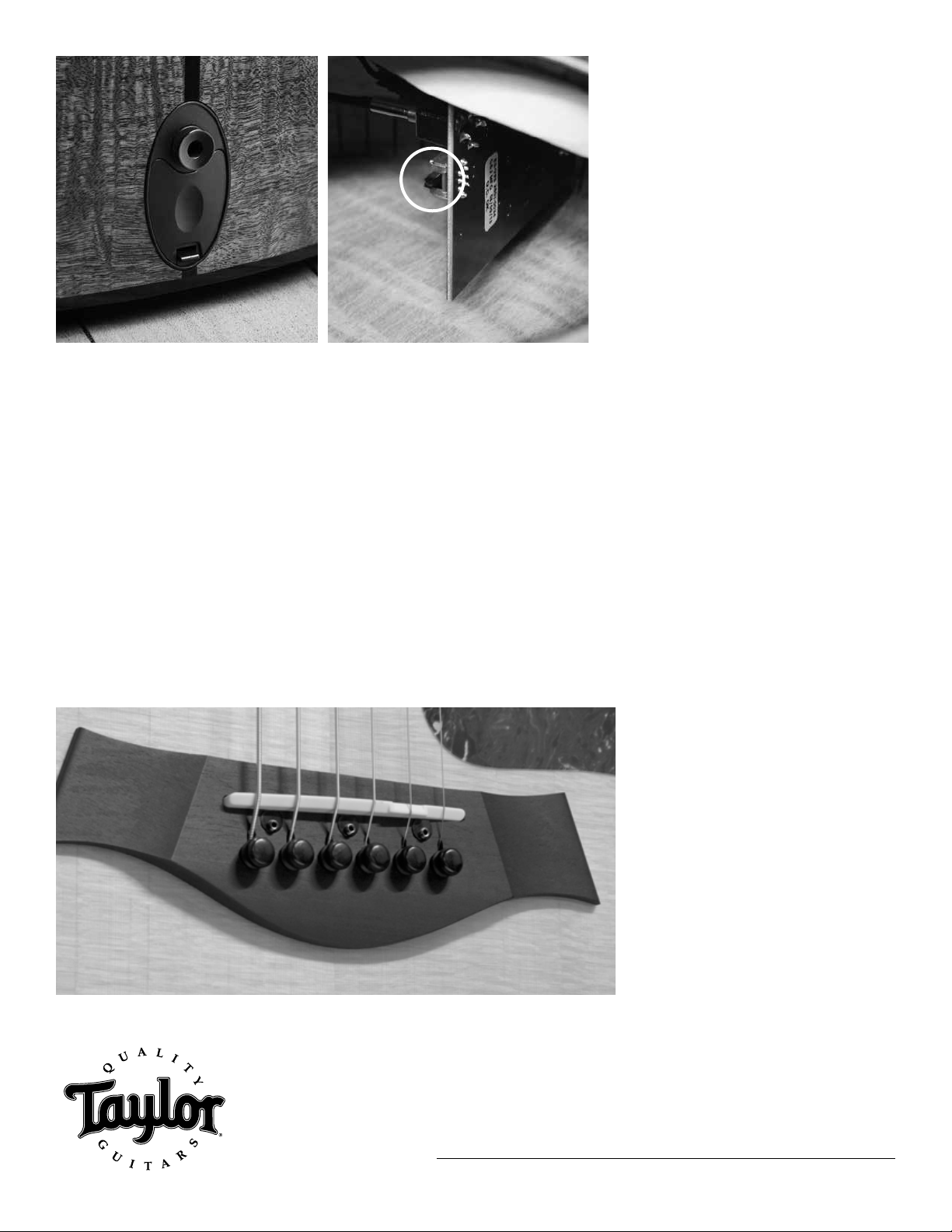
Battery Usage
The Expression System 2 requires one 9-volt
battery. Taylor recommends Duracell®for op-
timal performance and long life. A new battery
will provide 40-50 hours of plugged-in use.
The ES2 conserves battery life using a stan-
dard, automatic on/off system. The pickup is
in an “off” state until a cable is inserted, which
activates the preamp. Removing the cable will
return the system to “off” mode and conserve
battery life. An LED battery life indicator is vis-
ible and located inside the soundhole on the
preamp circuit board.
If your amplified tone begins to sound distorted,
the battery most likely needs to be replaced.
To change the battery, release the clip on the
battery carriage (located along the tail line of
Your Taylor guitar features the Taylor Expression System 2 (ES2), a revolutionary pickup
design that delivers the latest in Taylor’s ongoing innovation in acoustic guitar amplification. The
heart of the Expression System 2 is Taylor’s patented behind-the-saddle pickup, which features three
uniquely positioned and individually calibrated pickup sensors. The location of the sensors enables
a more dynamic range of acoustic sound to be captured than ever before. Together with Taylor’s
custom-designed “professional audio”-grade preamp, this system produces exceptional amplified tone
and responsiveness. On stage through a PA, plugged into your favorite acoustic amplifier, or direct into
recording software, the Expression System 2 faithfully conveys the voice of your Taylor guitar.
The Taylor Expression System 2 also operates through a proprietary 9-volt battery compartment and
easy-to-use volume and tone controls.
Expression System 2 tone controls:
(L-R) Volume, Treble, Bass
continued on back