TB Wood's Sure-Grip Instruction Manual

Installation & Maintenance Manual
Sure-Grip®
Idler Bushing
P-5071-TBW
Form 885D
2TB Wood’s • 888-829-6637 P-5071-TBW • Form 885D
SH-BB 1/4-20NC 5 ft. lb.
SD-BB 1/4-20NC 5 ft. lb.
SK-BB 5/16-18NC 8 ft. lb.
SF-BB 3/8-16NC 15 ft. lb.
E-BB 1/2-13NC 30 ft. lb.
Idler Cap Screw Torque
The Sure-Grip tapered, QD-style interchangeable idler bushing offers flexible and easy installation while
providing many hours of reliable service. To ensure that the bushing performs as specified it must be
properly installed. Before beginning, make sure the correct size and quantity of parts are available for the
installation.
WARNING:
Rotating equipment must be properly guarded.
It is the responsibility of the user to properly guard all rotating equipment to comply with OSHA
or any applicable regulations. Failure to properly guard may contribute to severe injury
should someone come in contact with the rotating parts or should the rotating part fail.
WARNING:
DO NOT use Wood’s products on any primary aircraft drive or any other drive which could
endanger human life should a drive component fail.
WARNING:
It is essential that the idler assembly be installed
as close to mounting structure as possible to minimize overhung loads.
Excessive loads may cause a premature failure of the stud and/or bearings of the idler bushing.
INSTALLATION
IMPORTANT – Do not use lubricants in this installation
1. Thoroughly inspect the bore of the mating hub and the tapered surface of the idler bushing. Any paint,
dirt, grease, oil, etc. MUST be removed.
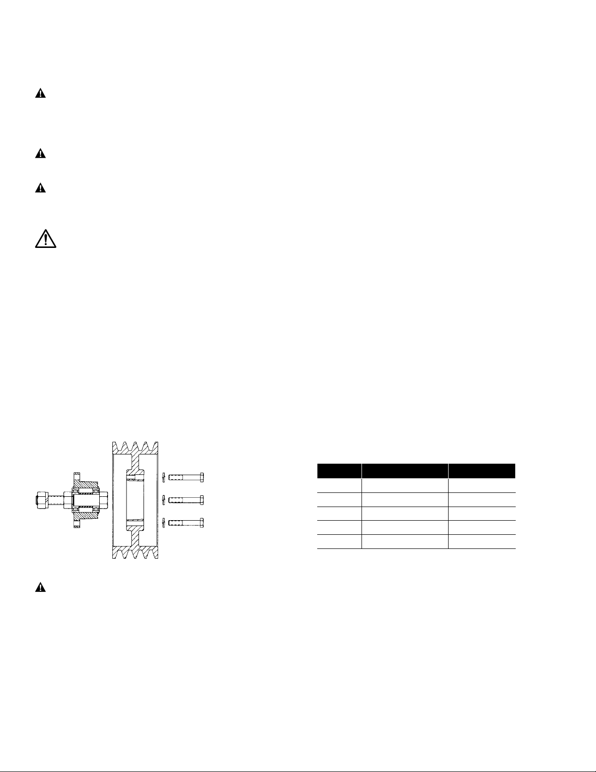
2.Place the idler bushing in the mating hub. Align the drilled holes in the mating hub with the threaded
holes in the idler bushing flange. Insert the cap screws, with lock washers, through the drilled holes in
the mating hub into the tapped holes in the idler bushing flange and finger-tighten, see Figure 1. Using
a torque wrench, tighten all caps screws evenly and progressively in rotation to the torque value listed
in Table 1.
WARNING:
The tightening force on the screws is multiplied many times by the wedging action of the
bushing’s tapered surface. If extreme tightening force is applied, or if a lubricant is used, bursting
pressures will be created in the hub of the mating part.
Do not attempt to over tighten cap screws to a point where the bushing flange touches the face of
the mating part. These torque values must be adhered to or idler assembly will fail prematurely.
Table 1 – Cap Screw Tightening Torque
Figure 1
The Sure-Grip tapered, QD-style interchangeable idler bushing offers flexible and easy installation while
providing many hours of reliable service. To ensure that the bushing performs as specified it must be properly
installed. Before beginning, make sure the correct size and quantity of parts are available for the installation.
WARNING: Rotating equipment must be properly guarded. It is the responsibility of the user to
properly guard all rotating equipment to comply with OSHA or any applicable regulations. Failure to
properly guard may contribute to severe injury should someone come in contact with the rotating
parts or should the rotating part fail.
WARNING: DO NOT use TB Wood’s products on any primary aircraft drive or any other drive
which could endanger human life should a drive component fail.
WARNING: It is essential that the idler assembly be installed as close to mounting structure as
possible to minimize overhung loads. Excessive loads may cause a premature failure of the stud
and/or bearings of the idler bushing.
WARNING: Cancer - www.P65Warnings.ca.gov
INSTALLATION
IMPORTANT – Do not use lubricants in this installation
1. Thoroughly inspect the bore of the mating hub and the tapered surface of the idler bushing. Any paint, dirt,
grease, oil, etc. MUST be removed.
2. Place the idler bushing in the mating hub. Align the drilled holes in the mating hub with the threaded holes
in the idler bushing flange. Insert the cap screws, with lock washers, through the drilled holes in the mating
hub into the tapped holes in the idler bushing flange and finger-tighten, see Figure 1. Using a torque
wrench, tighten all caps screws evenly and progressively in rotation to the torque value listed in Table 1.
WARNING: The tightening force on the screws is multiplied many times by the wedging action
of the bushing’s tapered surface. If extreme tightening force is applied, or if a lubricant is used,
bursting pressures will be created in the hub of the mating part.
Do not attempt to over tighten cap screws to a point where the bushing ange touches the face of
the mating part. These torque values must be adhered to or idler assembly will fail prematurely.
Table 2 – Cap Screw Tightening Torque
Idler Cap Screw Torque
SH-BB 1/4-20NC 5 ft. lb.
SD-BB 1/4-20NC 5 ft. lb.
SK-BB 5/16-18NC 8 ft. lb.
SF-BB 3/8-16NC 15 ft. lb.
E-BB 1/2-13NC 30 ft. lb.

TB Wood’s • 888-829-6637 P-5071-TBW • Form 885D 3
To Remove:
1. Loosen and remove all of the cap screws from the idler assembly.
2. Insert the cap screws into the tapped holes in the mating hub. Evenly and progressively tighten the
cap screws until the idler bushing and mating hub separate.
3. Remove idler assembly from the mounting structure.
Replacement Parts:
Following is a list of the replacement bearings. SH-BB G275
SD-BB G275
SK-BB G276
SF-BB G276
E-BB G277
Bushing Replacement
Size Bearings
(2 per unit)
3.Mount the assembly to the mounting structure. Place lockwasher and then outer nut on idler bushing
stud, Figure 2. Using a torque wrench, tighten the outer nut to the value listed in Table 2.
Note: If the assembly will be threaded into a tapped hole in the mounting surface, extreme care
should be used to prevent the inner nut from turning against the bearings. Additional tightening force
on inner nut will cause bearings to fail prematurely.
WARNING
The inner nut has been tightened to 5 ft. lbs. DO NOT tamper with or retighten
above this value or the bearings will fail prematurely.
4. Make sure idler assembly is parallel with both the driveR and driveN shaft. Properly align the driveR,
driveN, and idler assembly by the four-point method illustrated in Figure 3, below.
SH-BB 1/2-13NC 60 ft. lb.
SD-BB 1/2-13NC 60 ft. lb.
SD-BB58 5/8-11NC 125 ft. lb.
SK-BB 3/4-10NC 225 ft. lb.
SF-BB 3/4-10NC 225 ft. lb.
SF-BB1 1-8NC 300 ft. lb.
E-BB 1 3/8-8NC 750 ft. lb.
Idler Cap Screw Torque
Table 2 – Outer Nut Tightening Torque
Note: The inner nut torque should not
exceed 5 ft. lbs. when reassembling.
Note: Straight edge must touch
two points on A and two points
on B and C.
Figure 3
Figure 2
3. Mount the assembly to the mounting structure. Place lockwasher and then outer nut on idler bushing stud,
Figure 2. Using a torque wrench, tighten the outer nut to the value listed in Table 2.
Note: If the assembly will be threaded into a tapped hole in the mounting surface, extreme care should be
used to prevent the inner nut from turning against the bearings. Additional tightening force on inner nut will
cause bearings to fail prematurely.
WARNING: The inner nut has been tightened to 5 ft. lbs. DO NOT tamper with or retighten
above this value or the bearings will fail prematurely.
4. Make sure idler assembly is parallel with both the driveR and driveN shaft. Properly align the driveR,
driveN, and idler assembly by the four-point method illustrated in Figure 3, below.
To Remove:
1. Loosen and remove all of the cap screws from the idler assembly.
2. Insert the cap screws into the tapped holes in the mating hub. Evenly and progressively tighten the cap
screws until the idler bushing and mating hub separate.
3. Remove idler assembly from the mounting structure.
Replacement Parts:
Following is a list of the replacement bearings.
Note: The inner nut torque should not exceed 5 ft. lbs. when reassembling.
To Remove:
1. Loosen and remove all of the cap screws from the idler assembly.
2. Insert the cap screws into the tapped holes in the mating hub. Evenly and progressively tighten the
cap screws until the idler bushing and mating hub separate.
3. Remove idler assembly from the mounting structure.
Replacement Parts:
Following is a list of the replacement bearings. SH-BB G275
SD-BB G275
SK-BB G276
SF-BB G276
E-BB G277
Bushing Replacement
Size Bearings
(2 per unit)
3.Mount the assembly to the mounting structure. Place lockwasher and then outer nut on idler bushing
stud, Figure 2. Using a torque wrench, tighten the outer nut to the value listed in Table 2.
Note: If the assembly will be threaded into a tapped hole in the mounting surface, extreme care
should be used to prevent the inner nut from turning against the bearings. Additional tightening force
on inner nut will cause bearings to fail prematurely.
WARNING
The inner nut has been tightened to 5 ft. lbs. DO NOT tamper with or retighten
above this value or the bearings will fail prematurely.
4. Make sure idler assembly is parallel with both the driveR and driveN shaft. Properly align the driveR,
driveN, and idler assembly by the four-point method illustrated in Figure 3, below.
SH-BB 1/2-13NC 60 ft. lb.
SD-BB 1/2-13NC 60 ft. lb.
SD-BB58 5/8-11NC 125 ft. lb.
SK-BB 3/4-10NC 225 ft. lb.
SF-BB 3/4-10NC 225 ft. lb.
SF-BB1 1-8NC 300 ft. lb.
E-BB 1 3/8-8NC 750 ft. lb.
Idler Cap Screw Torque
Table 2 – Outer Nut Tightening Torque
Note: The inner nut torque should not
exceed 5 ft. lbs. when reassembling.
Note:
Straight edge must touch
two points on A and two points
on B and C.
Figure 3
Figure 2
Note: Straight edge must
touch two points on A and two
points on B and C.
Figure 3
Figure 2
Table 2 – Outer Nut Tightening Torque
Idler Cap Screw Torque
SH-BB 1/2-13NC 60 ft. lb.
SD-BB 1/2-13NC 60 ft. lb.
SD-BB 58 5/8-11NC 125 ft. lb.
SK-BB 3/4-10NC 225 ft. lb.
SF-BB 3/4-10NC 225 ft. lb.
SF-BB1 1-8NC 300 ft. lb.
E-BB 1 3/8-8NC 750 ft. lb.
Bushing
Size
Replacement
Bearings
(2 per unit)
SH-BB G275
SD-BB G275
SK-BB G276
SF-BB G276
E-BB G277

P-5071-TBW Form 885D 2/19
www.tbwoods.com
2000 Clovis Barker Road
San Marcos, TX 78666
512-353-4000
The Brands of Altra Motion
Couplings
Ameridrives
www.ameridrives.com
Bibby Turboex
www.bibbyturboex.com
Guardian Couplings
www.guardiancouplings.com
Huco
www.huco.com
Lamiex Couplings
www.lamiexcouplings.com
Stromag
www.stromag.com
TB Wood’s
www.tbwoods.com
Linear Systems
Thomson
www.thomsonlinear.com
Warner Linear
www.warnerlinear.com
Geared Cam Limit Switches
Stromag
www.stromag.com
Engineered Bearing Assemblies
Kilian
www.kilianbearings.com
Electric Clutches & Brakes
Matrix
www.matrix-international.com
Stromag
www.stromag.com
Warner Electric
www.warnerelectric.com
Deltran
www.thomsonlinear.com
Belted Drives
TB Wood’s
www.tbwoods.com
Heavy Duty Clutches & Brakes
Twiex
www.twiex.com
Stromag
www.stromag.com
Svendborg Brakes
www.svendborg-brakes.com
Wichita Clutch
www.wichitaclutch.com
Gearing & Specialty Components
Bauer Gear Motor
www.bauergears.com
Boston Gear
www.bostongear.com
Delevan
www.delevan.com
Delroyd Worm Gear
www.delroyd.com
Nuttall Gear
www.nuttallgear.com
Engine Braking Systems
Jacobs Vehicle Systems
www.jacobsvehiclesystems.com
Precision Motors & Automation
Kollmorgen
www.kollmorgen.com
Miniature Motors
Portescap
www.portescap.com
Overrunning Clutches
Formsprag Clutch
www.formsprag.com
Marland Clutch
www.marland.com
Stieber
www.stieberclutch.com
TB Wood’s Facilities
North America
USA
440 North Fifth Avenue
Chambersburg, PA 17201 - USA
888-829-6637 * 717-264-7161
Belted Drives and Elastomeric
Couplings
Customer Service
1-888-829-6637 (Press #5)
For Application Support
1-888-829-6637 (Press #7)
2000 Clovis Barker Road
San Marcos, TX 78666 - USA
1-888-449-9439
General Purpose Disc Couplings
Customer Service
1-888-449-9439
4970 Joule St
Reno, NV 89502 - USA
775-857-1800
Canada
9779 45 Ave NW
Edmonton, AB T6E 5V8 - Canada
+1 780-439-7979
6305 Danville Road
Mississauga, ON L5T 2H7 - Canada
1-800-829-6631
1073 Rue Bégin
Saint-Laurent, QC H4R 1V8 - Canada
+1 514-332-4812
Mexico
Comisión Federal de Electricidad 850,
Industrial San Luis,
San Luis, S.L.P., 78395 - Mexico
+52 444 137 1500
Europe
Merchant Drive, Hertford
Hertfordshire SG13 7BL - England
+44(0)1992 501900
Elastomeric Couplings
Neither the accuracy nor completeness of the information contained in this publication is guaranteed by the company and may be subject to change in its sole discretion. The operating
and performance characteristics of these products may vary depending on the application, installation, operating conditions and environmental factors. The company’s terms and
conditions of sale can be viewed at http://www.altramotion.com/terms-and-conditions/sales-terms-and-conditions. These terms and conditions apply to any person who may buy,
acquire or use a product referred to herein, including any person who buys from a licensed distributor of these branded products.
©2019 by TB Wood’s LLC. All rights reserved. All trademarks in this publication are the sole and exclusive property of TB Wood’s LLC or one of its afliated companies.
The Brands of Altra Motion
TB Wood’s Facilities
Popular Switch manuals by other brands


AVM
AVM Fritz!Box 7490 Installation and operation

schmersal
schmersal TFH 232-11UEDR operating instructions

SMC Networks
SMC Networks SMC6709GL2 Technical specifications

The GigRig
The GigRig G3 S quick start guide

Wegener
Wegener Unity RF Switch Installation & operating guide

HP
HP A3100-48 v2 Disassembly instructions