HomeSeer HS-WX300 User manual

HS-WX300 User Guide
Online manual for the HS-WX300 In-wall Dimmer & Switch
Overview
HS-WX300 is a Z-Wave in-wall light switch that may be configured to operate as either a dimmer switch or an on/off switch. It may be installed with or
without a neutral wire and it works with both wired and wireless companion switches in 3-way circuit configurations. This switch has been designed,
tested and certified for use in the United States and Canada.
Important
WARNING RISK OF FIRE | RISK OF ELECTRICAL SHOCK | RISK OF BURNS
DO NOT USE THIS SWITCH TO CONTROL ANYTHING THAT MAY PRESENT A HAZARD WHEN CONTROLLED REMOTELY OR USED IN AN
UNATTENDED FASHION. DO NOT USE WITH MEDICAL AND LIFE SUPPORT INSTRUMENTS.
To Reduce the Risk of Overheating And Possible Damage To Other Equipment, Do Not Install To Control A Receptacle, A Motor-CAUTION:
Operated Appliance, A Fluorescent Lighting Fixture, Or A Transformer-Supplied Appliance.
Circuit Types
Most lighting loads are powered with line (120 VAC) and neutral wires. The line wire always runs through the wall switch box but the neutral may not
be present there. If the neutral wire is present, use the 3-wire method below. If no neutral is present, use the 2-wire method. For 3-way circuits, a
neutral is only required at the companion switch location (using HS-WA100+ or standard 3-way switches).
Single Switch, 3-Wire Circuit Single Switch, 2-Wire Circuit
Multi Switch (3-Way) Wiring for 2-Wire & 3-Wire Circuits
™

1.
2.
3.
4.
5.
6.
7.
8.
1.
2.
Installation
Tools required
Medium Standard (flat head) Screwdriver
Medium Philips Screwdriver
Wire Cutter & Stripper
Steps
Shut off power to the circuit at the circuit breaker or fuse box.
VERIFY power is OFF before continuing!
Remove existing switch’s wall plate and mounting screws. Carefully remove the existing switch from the electrical box but leave the wires
connected.
There may be up to five wires connected to the existing switch. Make note of these wires and label, if necessary, to ensure correct installation
of the HS-WX300. You will need to match these wires with the corresponding screw terminals on the HS-WX300.
Note: LINE, and LOAD wires are required for every installation. If a NEUTRAL wire is present, we recommend using that also for
best performance, particularly for dimming loads. Wires are usually color-coded fore easy identification. However, colors can
deviate from what’s shown in the list below, depending upon the original installer. We recommend using a multi-meter to verify
which wire is actually connected to power before wiring. In general, the colors follow the convention below.
LINE (120 VAC) - Black (connected to power)
NEUTRAL - White (this wire is often tied to other neutral wires and may require a jumper to connect with the HS-WX300)
LOAD - Black (connected to load)
GROUND — Green or Bare
TRAVELER — Red/Other (only used in 3-way circuits)
Disconnect the wires from the existing switch and attach those wires to the HS-WX300 using the screw terminal connectors on the back with
the following procedure:
Strip 16 mm (5/8”) insulation from each wire*.
With a screw driver, loosen each screw terminal by rotating the screw counter-clockwise a few turns until resistance is felt.
There are two holes on the back of the switch near each screw terminal. Insert the stripped wire into one of these holes and tighten the screw
terminal to secure the connection. Connections should be snug. *all wires should be 14 AWG or larger rated at 80°C or higher. Tightening
torque should be 12 lbf-in (14kgf-cm). .Use copper wire only
Carefully install the wired switch back into the electrical box and reattach the trim plate.
Configuration
Changing Switch Mode
(Must be done BEFORE Z-Wave inclusion)
HS-WX300 may be configured to operate as an ON-OFF switch or as a DIMMER. By default, it will operate as a dimmer. To change the switch mode,
follow these steps:
Press & hold the small button located on the metal yoke next to the column of LEDs, if the trim plate is already installed, in rapidOR
succession, tap the top paddle 3 times, then press & hold the top paddle for 3 seconds (tap-tap-tap-press & hold)
Observe the behavior of the LEDs
If all LEDs blink green 3 times, HS-WX300 is configured to function as a dimmer
If the bottom LED blinks blue 3 times, HS-WX300 is configured to function as an on-off switch

1.
2.
3.
1.
2.
1.
Changing Wire Mode
HS-WX300 may be installed with a neutral wire (3-wire mode) or without a neutral wire (2-wire mode). Selecting the correct wire mode will yield the
best results, especially if the switch is configured as a dimmer. By default, 3-wire mode is enabled. To change the wire mode (at the switch):
Turn the power off
In rapid succession, tap the paddle 2 times, then press & hold the top paddle for 3 seconds (tap-tap-press & hold)top
Observe the behavior of the LEDs
If the bottom 3 LEDs flash white 3 times, HS-WX300 is configured for 3-wire mode
If the bottom 2 LEDs flash white 2 times, HS-WX300 is configured for 2-wire mode
Note: Wire mode may also be changed by the hub using Z-Wave parameter 32. See the Z-Wave Parameters section at the end of this user guide.
Z-Wave Inclusion or Exclusion
Follow this 2-step procedure to add (or remove) your new HomeSeer switch to (or from) your Z-Wave network:
Put your Z-Wave controller into inclusion (or exclusion) mode. Consult your controller’s manual if you’re unsure how to do this.
In rapid succession, tap the paddle 2 times, then press & hold the bottom paddle for 3 seconds (tap-tap-press & hold). This willbottom
initiate the inclusion (or exclusion) process. The switch will default to dimmer mode after Z-Wave exclusion.Note:
Factory Reset
To be used only in the event that the network primary controller is lost or otherwise inoperable.
In rapid succession, tap the paddle 3 times, then tap the bottom paddle 3 times. If all LEDs flash white 5 times, factory reset wastop
successful. If not, repeat this procedure.
As this must be done very quickly, we recommend using 2 fingers for this operation; one on each paddle!Note: The switch will default to 3-wire mode and dimmer mode after factory reset.Note:
Association
This product supports Group 1 and Group 2 Associations with up to five Z-Wave devices per group. Group 1 supports Lifeline Communication, Group
2 supports Basic Set, refer to your controller manual for instructions on setting up these features.
Operation
Your new HomeSeer switch may be operated locally (by pressing the paddle) or remotely using a Z-Wave compatible hub or system
Local Control
Press (tap) the top of the paddle to power the load.
Press (tap) the bottom of the paddle to cut power to the load.
If configured as a dimmer, press and hold the top or bottom of the paddle increase or decrease the dim level.
Remote Control
On / Off / Dim control is available remotely using wireless Z-Wave commands. Consult your controller manual for details.
HomeSeer Compatibility
Your new HomeSeer switch is Z-Wave certified and is ready to be used with a wide variety of home automation hubs and controllers. All features are
fully supported by HomeSeer systems but some (see below) may not be fully supported by other controllers. If you’re usingAdvanced Features
another brand of controller, be sure to check with that company to determine compatibility.
Advanced Features
Your new HomeSeer switch includes advanced features that may be accessed with HomeSeer and other systems.
Multi-tap scene control or event triggering
Tapping the top or bottom of the paddle 1, 2, 3, 4 or 5 times in rapid succession will broadcast Z-Wave central scene commands to the hub. These
commands may be used to trigger automations (like HomeSeer events).
RGB LED Indicators
The color of all LED indicators may be controlled with Z-Wave parameter commands from the hub. This may be done manually or via automations, if
supported by the hub. HomeSeer hubs are designed to send these parameter commands with event actions.
Normal mode: LED indicators glow to reflect the on/off/dim status of the connected load using a palette of 7 possible colors (red, green,
blue, cyan, magenta, yellow, white).

Status mode: Individual LEDs can be controlled to reflect the status of nearly anything in the home. For example, one LED can be
programmed to glow yellow when the garage door is open. Another LED can blink red when motion is sensed in the driveway. The
possibilities are endless.
Switching between normal mode and status mode: HS-WX300 switches operate in normal mode by default unless or until a status
command is received. When that happens, normal mode is suspended and the switch goes into status mode. It will stay in status mode until
all status LEDs are turned off. At that point, the switch will revert to normal mode.
If a switch is operating in status mode, manually dimming it will cause the LEDs to operate temporarily in normal mode. After theNote:
dimming operation is complete, the switch will revert to status mode.
Non-HomeSeer Compatibility
The special features of this switch are supported using a number of different Z-Wave technologies. HomeSeer systems are designed to support these
technologies and will provide the most seamless operation of these features. However, other systems may also provide satisfactory results depending
on the level of support they provide for these same technologies. If you’re using a non-HomeSeer system, use the information below and consult with
your system manufacturer to determine the level of compatibility.
Multi-tap scene control or event triggering
This feature uses the Z-Wave CENTRAL SCENE command class. If the system supports this command class AND utilizes a general interrogation
process for inclusion, this feature should work. However, if the system employs an inclusion process based on the Z-Wave product ID, then specific
product support would need to be implemented.
RGB LED Indicators
This feature is supported using Z-Wave parameter commands. Most Z-Wave certified systems provide a method for issuing parameter commands to
individual products. HomeSeer systems simplify the use of this feature by providing event actions to send parameter commands. A complete list of
parameters may be found on the next page.
Instant Status
This feature is supported using a Z-Wave SWITCH (dimmer mode) and SWITCH (on-off switch mode) andMULTILEVEL REPORT BINARY REPORT
the CENTRAL SCENE command class. All Z-Wave certified systems should support the SWITCH feature.MULTILEVEL REPORT
Attention SmartThings users
A special is required to enable your hub to use the advanced features of this switch. Information about installing this may be found at:device handler
SmartThings
Z-Wave SmartStart
SmartStart enabled products can be added into a Z-Wave network by scanning the Z-Wave QR Code* with a controller providing SmartStart inclusion.
No further action is required and the SmartStart product will be added automatically within 10 minutes of being switched on in the network vicinity.
*QR Code is located on the HS-WX300 metal yoke under the switch paddle.
Interoperability
This product can be operated in any Z-Wave network with other Z-Wave certified devices from other manufacturers. All mains operated nodes within
the network will act as repeaters regardless of vendor to increase reliability of the network
Z-Wave Parameters
Use the parameters below to adjust HS-WX300 configuration settings
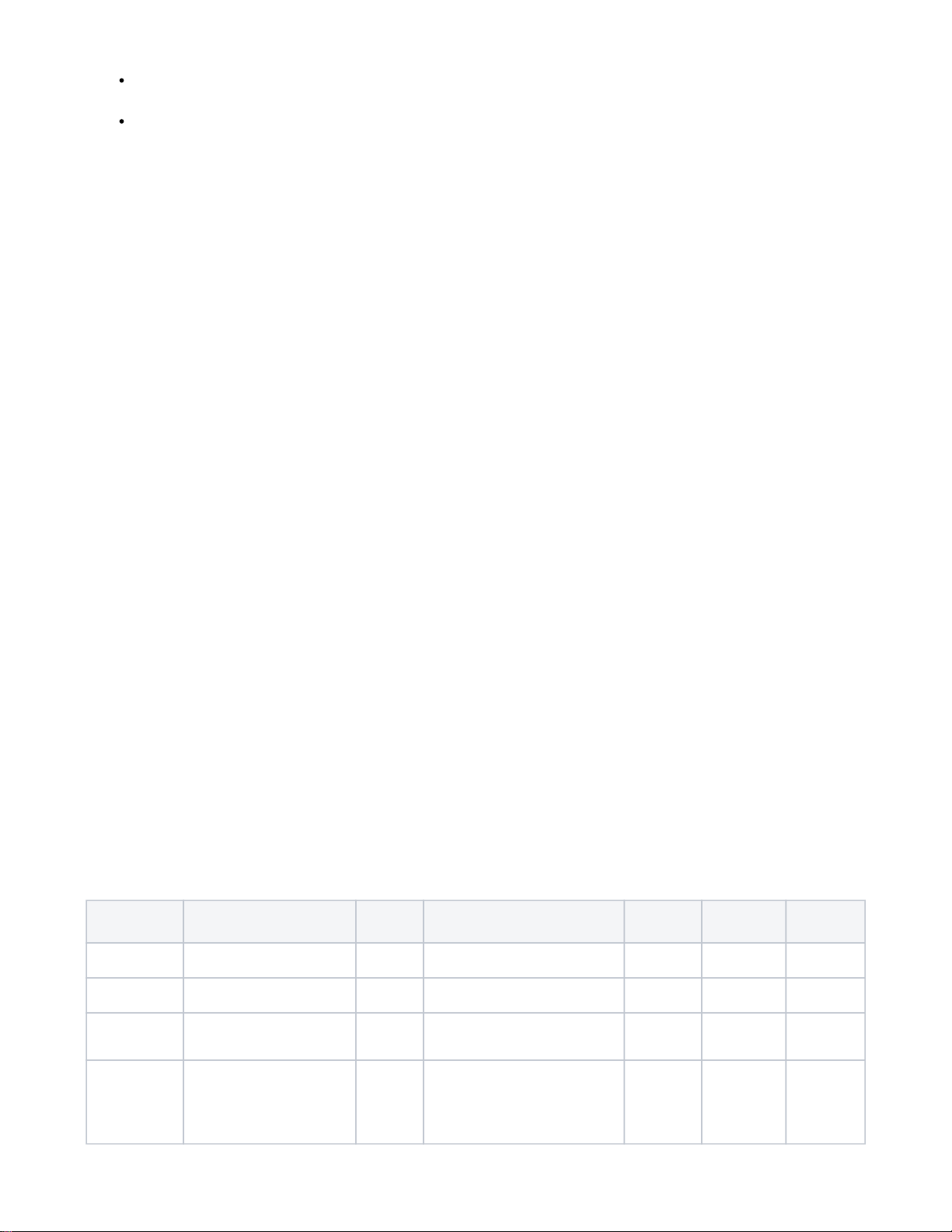
Parameter Description Bytes Value Default Dimmer
Mode Switch
Mode
3 Sets bottom LED operation (in
normal mode) 1 0 = all LED ON if load is OFF
1 = all LED OFF if load is OFF 1 Y Y
4 Sets paddle’s load orientation 1 0 = Top of Paddle turns load ON
1 = Bottom of Paddle turns load ON 0 Y Y
5 Sets the lowest dimming threshold 1 Possible values: 1-14
3-wire mode (1=16%, 14=25%)
2-wire mode (1=25%, 14=30%)
1 Y N
6 Enables/Disables Central Scene
and multiple tap functions 1 0 = Central Scene Enabled, controls
load with delay. Enables Multi-tap and
press and hold
1 = Central Scene Disabled, controls
load instantly. Disables multi-tap,
central scene, press and hold
0 Y Y

11 Set dimmer Ramp rate for remote
control 1 Possible values: 0-90
0=No delay (instant ON), 1=1 second 3 Y N
12 Set dimmer Ramp rate for local
control 1 Possible values: 0-90
0=No delay (instant ON), 1=1 second 3 Y N
13 Sets the display mode of the LEDs 1 0=Normal mode (LEDs show load
status)
1=Status mode (custom LED status)
0 Y Y
14 Sets the Normal display mode
LED color 1 Possible values: 0-6
0=White, 1=Red, 2=Green, 3=Blue,
4=Magenta, 5=Yellow, 6=Cyan
0 Y Y
21 Sets the Status mode LED 1
(bottom) color 1
Possible values: 0-7
0=Off, 1=Red, 2=Green, 3=Blue,
4=Magenta, 5=Yellow, 6=Cyan, 7=White
0
Y Y
22 Sets the Status mode LED 2 color 1
23 Sets the Status mode LED 3 color 1
24 Sets the Status mode LED 4 color 1
25 Sets the Status mode LED 5 color 1
26 Sets the Status mode LED 6 color 1
27 Sets the Status mode LED 7 (top)
color 1
30 Sets the dimmer Blink frequency
for All LEDs in Status mode 1 Possible values: 0, 1-255
0=No blink, 1=100ms ON then 100ms
OFF
5 Y Y
31 Sets LED(s) 1-7 to Blink in Status
mode 1 Bitmask defines specific LEDs to enable
for blinking:
Note: this decimal value is derived from
a hex code calculation
based on the following:
Bit 0 = led 1, Bit 1 = led 2, Bit 2 = led 3,
Bit 3 = led 4, Bit 4 = led 5,
Bit 5 = led 6, Bit 6 = led 7
IE: value of 1 = first LED, 64 = led 7
0 Y Y
32 Sets the Wire mode / no neutral
mod of the switch 1 0 = 3 wire mode (Neutral, Line, & Load)
1 = 2 wire mode (Line & Load) 0 Y Y
Specifications
Power Requirements 120VAC / 60 Hz
Max Load Incandescent | Dimmable CFL/LED 600 watts | 300 watts
Incandescent
De-rating Double-gang Box 500 watts
Triple-gang Box 400 watts
Z-Wave Frequency 908.4/916 MHz (US/CAN)
Range 100+ ft. (line of sight)
Certifications UL (US, Canada), FCC/IC, Z-Wave Plus
UL
Specifications For indoor use only | Operating ambient temperature 0-40°C | Method of mounting included: Independently mounted (Vertical
position only) | Operating control, Type 1.B action | Pollution Degree 2 | Rated Impulse Voltage 2500 V | Software Class A
Warranty
®

HomeSeer warrants to the original purchaser that this product, for the warranty period, will be free from material defects and workmanship. This
warranty is subject to proper installation and operation of the product. HomeSeer’s sole obligation, under this warranty, is to repair, replace or correct
any defect that was present at the time of delivery. This warranty does not extend to consequential or incidental damage to other products that may be
used with this product. Warranty claims must be submitted in writing directly to HomeSeer at . Warranty period: limited 2 years fromHomeSeer.com
date of purchase
FCC statements:
This device complies with part 15 of the FCC rules. Operation is subject to the following two conditions: (1) this device may not cause harmful
interference, and (2) this device must accept any interference received, including interference that may cause undesired operation.
NOTE: The manufacturer is not responsible for any radio or TV interference caused by unauthorized modifications or changes to this equipment. Such
modifications or changes could void the user’s authority to operate the equipment.
IC statements
This device complies with Part 15 of the FCC Rules and with RSS of Industry Canada. Operation is subject to the following two conditions:
(1) This device may not cause harmful interference, and
(2) this device must accept any interference received, including interference that may cause undesired operation.
Le présent appareil est conforme aux CNR d'Industrie Canada applicables aux appareils radio exempts de licence. L'exploitation est autorisée
aux deux conditions suivantes :
(1) l'appareil ne doit pas produire de brouillage, et
(2) l'utilisateur de l'appareil doit accepter tout brouillage radioélectrique subi, même si le brouillage est susceptible d'en compromettre le
fonctionnement.
This Class B digital apparatus complies with Canadian ICES-003.
Cet appareil numérique de la classe B est conforme à la norme NMB-003 du Canada.
Supplier’s Declaration of Conformity
47 CFR 2.1077 Compliance Information
Responsible Party – US Contact Information
10 Commerce Park North, Unit 10
Bedford, NH 03110 United States
Model: WD700
https://homeseer.com/support-home
This product employs or practices certain features and/or methods of the following U.S. Patents: U.S. Patent Nos.6,891,838, 6,914,893 and 7,103,511.
Table of contents
Other HomeSeer Switch manuals
Popular Switch manuals by other brands

Juniper
Juniper QFX5200 Hardware guide

SMC Networks
SMC Networks TigerStack II SMC8926EM Management guide

StarTech.com
StarTech.com C2-D46-UAC-CBL-KVM quick start guide

Draytek
Draytek VigorSwitch FX2120 quick start guide

Extreme Networks
Extreme Networks BlackDiamond 10808 Hardware installation guide

Western Telematic
Western Telematic IPS-4 user guide