TBB BML User manual

BML battery monitor manual
TBB POWER CO., LTD.
BML
Battery Monitor Manual
Version: A1.1
April. 2017

BML battery monitor manual
TBB POWER CO., LTD.
WARNING : FIRE HAZARD
SUITABLE FOR MOUNTING ON CONCRETE OR OTHER
NON- COMBUS TABLE SURFACE ONLY
CAUTION : THE DC AND AC BREAKER MUST HAVE BEEN
TURNED OFF BEFORE SERVICING
MADE IN CHINA

BML battery monitor manual
TBB POWER CO., LTD.
Disclaimer
Unless specially agreed in writing, TBB Power Co.,Ltd
Take no warranty as to the accuracy, sufficiency of suitability of any technical or other
information provided in this manual or other documentation.
Assumes no responsibility or liability for loss or damage, whether direct, indirect,
consequential or incidental, which might arise out of the use of such information
About this Manual
This manual describes our product features and provides procedure of installations. This manual
is for anyone intending to install our equipment.
General Description
Thanks for choosing TBB product.
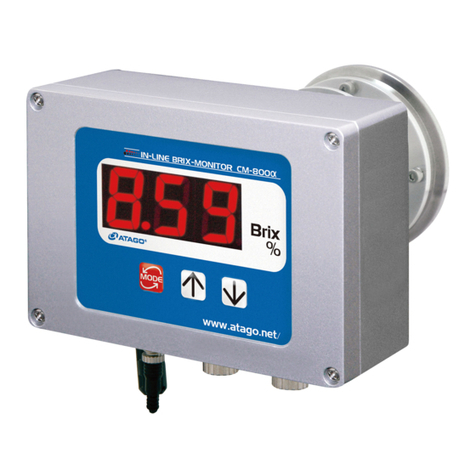
The BML series battery monitor features microprocessor controlled combined with high
resolution measuring system for lithium battery voltage and charge/discharge current . With
built in software, BML series can calculated consumed AH/KWH and remaining AH/KWH, and
display battery voltage and battery current as well.
BML could record all battery activities since the first installation (max 200 records). Apart from
discharging and charging, multiple other factors are considered including battery size, age ratio
of battery etc. With shunt, even the smallest leakage current can be detected and recorded to
guarantee the accuracy.
Compared with conventional indicating meters, small current can be measured and read exactly
with this device. With this feature, latent consumers (insulation fault, wrong connections,
standby unit etc) can be recognized immediately. Meantime, through additional sensor second
battery voltage can be measured and displayed.
With the optional DOD protection unit, battery low voltage protection level can be programmed
and alarm cam will be sent once reaching the limit to avoid battery damage due to deep
discharge. In the meantime, it can be used to drive the battery protection device to shut off the
battery against further discharge.
Battery voltage of service battery
Each Cell voltage of the lithium battery
Battery current : charging and discharging
Battery residual capacity in AH
Battery capacity in %
Programmable for protection point
RS485 is available
Available model: 100A, 200A and 400A.

BML battery monitor manual
TBB POWER CO., LTD.
Schematic diagram
Voltage and
Current
Sampling
BML Monitor
DOD
Protection
Voltage of Cells
Sampling
RS485
Model Name
BML XXX Y
Item
Description
BM
L
BML
Battery monitor for lithium battery
XXX
100
The max current for battery
monitor
100A
200
200A
400
400A
Y
4
12V system
8
24V system
Available model
Model
Max Current
Battery voltage
Cell number of Lithium
battery
BML1004
100A
12Vdc/24Vdc
4cells
BML1008
100A
12Vdc/24Vdc
8cells
BML2004
200A
12Vdc/24Vdc
4cells
BML2008
200A
12Vdc/24Vdc
8cells
BML4004
400A
12Vdc/24Vdc
4cells
BML4008
400A
12Vdc/24Vdc
8cells
BML detects 12V/24V battery automatically.

BML battery monitor manual
TBB POWER CO., LTD.
Optional DOD model:
Compatible for
12Vdc
24Vdc
48Vdc
50A
RY50L
/
/
100A
CR100L/RY100L
CR100M
CR100S
200A
CR200LM
CR200LM
CR200S
400A
CR400L
CR400M
CR400S
Components
Monitor Module
Current Detector Module
SS (for 100A,200A model)
Current Detector Module
SH (for 400A model)

BML battery monitor manual
TBB POWER CO., LTD.
Dimension and Hole size
Monitor Module
101
101
43.45
35.6
4-φ3.5
43.1
101
81
87.64
87.64
SS
135
31.4
28
59
111
14
6
31.4
59
50
17
100

BML battery monitor manual
TBB POWER CO., LTD.
SH:

BML battery monitor manual
TBB POWER CO., LTD.
Installation Preparation
Material list

BML battery monitor manual
TBB POWER CO., LTD.
Item
Qty
Description
1
1
Front panel of Monitor Module
2
1
Monitor Module
3
1
Mounting holder
4
1
SS current detector
5
1
SS plate
6
1
Cable-L8-D/03,Cable for8cellsvoltage andDOD,
for BML1008 and BML2008
7
1
Cable-Service-Batt-Volt/01,Cable for Service battery
8
1
Screws,M3x12mm for holder mounting
9
3
Screws, M6 x 25mm for SS mounting
10
2
Screws M3x25mm for Monitor module mounting
11
5
Screw fixing expansion sleeve 4mm
12
5
Cable-Starter-Batt‐Volt/01, Cable for starter battery
13
1
Cable-Flex-50/30 or Cable-Flex-25/30,Cable for SS and negative connector
of battery
14
1
Cable-BM/03, Cable for SS and Monitor Module
15
1
Cable-L4-D/03, Cable for 4cells voltage and DOD, for BML1004 and
BML2004

BML battery monitor manual
TBB POWER CO., LTD.
Connector Description
Monitor Module
A
RS485 Communication
COM
B
Comm. port for Lithium battery energy
information
BM
C
Comm.Port for lithium battery cell voltage
and DOD dry contact
Cells+DOD
D
Cable fastener
Current Detector Module - SS
Take off the cover, you will see the connector of the SS.
A
Load -
B
BMcomm.Cable connector
C
BAT-

BML battery monitor manual
TBB POWER CO., LTD.
Cable preparation
Please prepare the following cables for installation
Model
lenght
comments
Cable-BM/03
3
The standard
Cable-Service-Batt-Volt/01
1
The standard
Cable-Starter-Batt-Volt/01
1
The standard
Cable-L8-D/03
3
for BML1008/BML2008
Cable-L4-D/03
3
for BML1004/BML2004
Cable-Flex-50/30
0.3
for SS200/SS200S
Cable-Flex-25/30
0.3
for SS100/SS100S
Cable-BM/03
T1
To Connect to SS or SH
T2
To Port BM of the monitor module
T3
To connect Cable-Starter-Batt‐Volt/01
T4
To connect Cable-Service-Batt-Volt/01
Cable-Service-Batt-Volt/01
T2:Service Batt+
T1
T1
To Connect to Service batt +
1
2
3
5
4
1
2
3
4
T1 To Shunt
T2 TO Monitor-BM
T3 Starter-Batt+
T4 Service-Batt+
橙
棕
绿
蓝
紫
白
红
黄
灰
红
红
灰
橙
棕
绿
蓝
紫
白
红
黄

BML battery monitor manual
TBB POWER CO., LTD.
T2
To connect to Cable-BM/03
Cable-Starter-Batt-Volt/01
T2: Starter Batt+
T1
T1
To Connect to Starter batt +
T2
To connect to Cable-BM/03
Cable-L8-D/03
T1
--
Connect to Port Cells+DOD of Monitor Module
T2
DOD
To connect to DOD module
T3
Bat cell3+
To connect to Batt Cell3 +
T4
Bat cell4+
To connect to Batt Cell4 +
T5
Bat cell2+
To connect to Batt Cell2 +
T6
Bat cell1+
To connect to Batt Cell1 +
T7
Bat cell8+
To connect to Batt Cell8 +
T8
Bat cell7+
To connect to Batt Cell7 +
T9
Bat -
To connect to Batt -
T10
Bat cell6+
To connect to Batt Cell6 +
T11
Bat cell5+
To connect to Batt Cell5 +
Connection schematic diagram
1
5
4
2
3
6
7
8
9
10
11
12
白
红
灰
黄
红
白
紫
蓝
绿
棕
橙T7:Bat ceLL8+
T8:Bat ceLL7+
T10:Bat ceLL6+
T11:Bat cell5+
T4:Bat ceLL4+
T3:Bat ceLL3+
T5:Bat ceLL2+
T6:Bat ceLL1+
T9:Bat -
DOD 白
红
3
2
1
T2
CELL8 CELL7 CELL2 CELL1
DOD
Bat cell8+
/BAT+
Bat
cell7+
Bat
cell6+
Bat
cell2+
Bat
cell1+
Bat -
SS/SH

BML battery monitor manual
TBB POWER CO., LTD.
Cable-L4-D/03
T1
--
To PortCells+DOD of Monitor Module
T2
DOD
To connect to DOD
T3
Bat cell3+
To connect to Batt Cell3 +
T4
Bat cell4+
To connect to Batt Cell4 +
T5
Bat cell2+
To connect to Batt Cell2 +
T6
Bat cell1+
To connect to Batt Cell1 +
T7
Bat -
To Batt -
Connection schematic diagram
1
5
4
2
3
6
7
8
9
10
11
12
白
红
白
红
绿
棕
橙
T3:Bat ceLL3+
T4:Bat ceLL4+
T5:Bat ceLL2+
T6:Bat ceLL1+
T7:Bat -
T2
DOD
3
2
1
T1
白
红
绿
棕
橙
CELL4 CELL3 CELL2 CELL1
DOD
Bat cell4+
/BAT+Bat cell3+Bat cell2+Bat cell1+Bat -
SS/SH

BML battery monitor manual
TBB POWER CO., LTD.
Cable-Flex-50/30 or Cable-Flex-25/30
Cable-Flex-50/30 and Cable-Flex-25/30 are to connect between battery negative connector and
BAT- connector of current detector module (SS or SH).
Installation Request
Work temperature: -20~60℃
Storage temperature:-40~85℃
Cooling: Natural cooling
Humility: 0%-95% non-condensing
Install the unit at the location where has well ventilation.
Recommended working temperature is 0~25℃
Recommended humility is around 50%
Installation
Professional electrical technician is required for the installation.
Please make sure BML is powered off during the installation which means the connection
between Cable-BM/03 and Cable-Starter-Batt-Volt/01 BAT+ / Cable-Service-Batt-Volt/01 S-BAT+ is
the last step of the installation.
Please make sure all of the equipments are powered off during the installation.
The location of SS/SH is recommended to be as close as possible to the battery. Shorter cable
between SS/SH and battery is better.
T1 T2

BML battery monitor manual
TBB POWER CO., LTD.
Monitor Module
Mounting holder is optional accessary. Please consult to the distributor or TBB Power if you need it.
Installation with the mounting holder
Installation without the mounting holder
87.6±0.50
87.6±0.50
2‐φ4.5(H=35)
TheWallHoleSize
2‐φ4*φ5*24
2-M3*25
2-M3*10 61,94
82+2
-0
82 +2
-0
87.6±0.50
87.6±0.50
4‐φ4.5(H=35)
TheWallHoleSize
4‐φ4*φ5*24
4-M4*25 2,80
2,80

BML battery monitor manual
TBB POWER CO., LTD.
SS/SH Installation
Connection to battery groups.
111,00
Φ3.50
Wall Openings
+
12V
100Ah
-
BAT+
12V
12V/100Ah
+
12V
100Ah
-
+
12V
100Ah
-
+
12V
100Ah
-
+
12V
100Ah
-
12V/400Ah
+
12V
100Ah
-
BAT+
24V
+
12V
100Ah
-
+
12V
100Ah
-
+
12V
100Ah
-
+
12V
100Ah
-
+
12V
100Ah
-
24V/100Ah 24V/200Ah
BAT-
BAT+
12V
BAT+
24V
BAT-
BAT-
BAT-
Cable-SG-050/30
orCable-SG-025/30
Cable-SG-050/30
orCable-SG-025/30
Cable-SG-050/30
orCable-SG-025/30
Cable-SG-050/30
orCable-SG-025/30
+
12V
100Ah
-
+
12V
100Ah
-
+
12V
100Ah
-
+
12V
100Ah
-
48V/400Ah
BAT-
Cable-Flex-50/30
Cable-Flex-25/30
BAT+
48V

BML battery monitor manual
TBB POWER CO., LTD.
SH Installation.
+
12V
100Ah
-
+
12V
100Ah
-
+
12V
100Ah
-
+
12V
100Ah
-
12V/400Ah
BAT+
12V
BAT-
DEVICE-

BML battery monitor manual
TBB POWER CO., LTD.
Operation
First power on
1. Confirm the connections are correct as the manual guided and fastened.
2. Connect Cable-Starter-Batt- Volt/01and Cable-BM/03.
3. Connect Cable-Service-Batt-Volt/01 and Cable-BM/03.
BML is powered on after the above steps.
4. Initial settings for BML.
a) Set battery type and capacity.
b) Set System datetime and installation datetime.
c) Battery capacity correction. Use a proper battery charger to charge the battery until
there is no alarms on the BML display.
d) Any change of the battery type or battery capacity setting needs a repeat for step b)
and c)
DO NOT plug out any connectors on the BML during it is working.
Power Off
a) If there is starter battery connected, disconnect the cable connect with the
starter battery first, then disconnect the cable connected to the service
battery,Cable-Service-Batt-Volt/01 and Cable-BM/03 to complete the shut down
of BML.
b) If there is no starter battery connected, disconnect disconnect the cable
connected to the service battery, Cable-Service-Batt-Volt/01 and Cable-BM/03 to
complete the shut down of BML.

BML battery monitor manual
TBB POWER CO., LTD.
Display
BML Menu
Click “Enter”
To Enter The Main Menu
Status >
Setting
Event
Information
Active Alarm
System’s Status Information
System’s Setting Information
Current Alarm Information
Event Logs
Hardware/Software Information
Home Page The First Level Menu
13.0V
-2.0A
100Min
65 Cyc
56%
03/12/2015 07:51:34
SERVICE:
CUR:
CYCLES:
STARTER:13.1V
1. Home page
Current Date
Battery SOC
Active Alarm
Remain Time Of Battery
Charging/Discharging Status
Battery Voltage
Battery Current
Charging/Discharging Cycles
Current Time
13.0V
-2.0A
100Min
65 Cyc
56%
03/12/2015 07:51:34
SERVICE:
CUR:
CYCLES:
STARTER:13.1V Battery Service Voltage
“Active Alarm”is ON, means the battery capacity correction is not completed.
“Active Alarm”is flashing, means the battery capacity correction is completed with
alarms. Please consult the technician.
“Active Alarm”is OFF, means the battery capacity correction is completed successfully.

BML battery monitor manual
TBB POWER CO., LTD.
2. Status
Status >
Setting
Event
Information
Active Alarm
01 0101HomepPage
Cell1
Cell2
Cell3
Cell4
3.25V
3.24V
3.25V
3.26V
Total 13.00V
Battery Manage System
0102
Voltage 13.0V
Current -2.0A
SOC 52%
RE Time 100Min
Cycles 65 Cycles
Battery Monitor
13.0V
-2.0A
100Min
65 Cyc
56%
03/12/2015 07:51:34
SERVICE:
CUR:
CYCLES:
STARTER:12.0V
0101
Voltage 13.0V
Current -2.0A
SOC 52%
RE Time 100Min
Cycles 65 Cycles
Battery Monitor
SOC: Battery State of Charge , 0%~100%
Voltage: Battery Voltage
Current:Battery current. “-”means discharged current.
Without “-” means charging current.
Cycles: Battery cycles
RE Time: Battery left to go.
Cell1
Cell2
Cell3
Cell4
3.25V
3.24V
3.25V
3.26V
Total 13.00V
Battery Manage System
0102
Total:Battery Voltage
Cell1~Cell8:Voltage of each cell.
Cell1~Cell4 for 12V battery,
Cell1~Cell8 for 24V battery.
Table of contents
