ATAGO CM-800A-DMF User manual

3534-E06
In-line Dimethylformamide Monitor
CM-800
-DMF
Instruction Manual
Cat.No.3534


1
CONTENTS
1.
Precautions for Use.................................................................................................................................................. 2
2.
Refractive Index and Dimet ylformamide(DMF) concentration................................................................ 8
(1)
W at is refractometer? ................................................................................................................................... 8
(2)
W at is t e Refractive Index? ...................................................................................................................... 8
(3)
DMF concentration(%) scale.......................................................................................................................... 8
(4)
Temperature correction.................................................................................................................................. 8
3.
Unpacking and Installation...................................................................................................................................... 9
(1)
Configuration ...................................................................................................................................................... 9
(2)
Unpacking...........................................................................................................................................................10
(3)
Installation .........................................................................................................................................................10
4.
Names and Functions of Components.............................................................................................................11
(1)
Instrument .........................................................................................................................................................11
(2)
Operation Display............................................................................................................................................12
(3)
AC Adapter AD-32, AD-33 or AD-34 (Optional)................................................................................12
5.
Mounting t e instrument and AC adapter AD-32 (AD-33 or AD-34) (Optional) ............................13
6.
Mounting t e Sample Inlet Unit..........................................................................................................................14
(1)
Installation of t e instrument wit t e sample inlet unit (optional): ............................................14
(2)
Installation of t e instrument wit out t e sample inlet unit (optional):......................................16
7.
Connecting t e Power Cable or AC Adapter AD-32 (AD-33 or AD-34) (Optional) ......................17
(1)
W en t e instrument is used alone..........................................................................................................17
(2)
W en t e AC adapter AD-32, AD-33 or AD-34 (Optional) is used.............................................18
8.
External Output........................................................................................................................................................19
(1)
Recorder output ..............................................................................................................................................19
(2)
RS-232C output ..............................................................................................................................................20
9.
Power Supply ............................................................................................................................................................24
(1)
W en t e instrument is used alone..........................................................................................................24
(2)
W en t e AC adapter AD-32, AD-33 or AD-34 (optional) is used..............................................24
10.
Measuring DMF solution(%) ..................................................................................................................................25
11.
Setting t e temperature scale (℃/°F)............................................................................................................26
12.
Setting t e Measurement Interval and Mode-S Level...............................................................................27
13.
Adjusting to t e Reference..................................................................................................................................28
14.
Temperature Correction .......................................................................................................................................29
15.
Setting t e Recorder Output ..............................................................................................................................30
16.
Cleaning t e Prism..................................................................................................................................................32
17.
Error Codes & Troubles ooting..........................................................................................................................33
18.
Consumable Parts and Optional Items ............................................................................................................34
(1)
Consumable Parts...........................................................................................................................................34
(2)
Optional Items..................................................................................................................................................34
19.
Specifications............................................................................................................................................................35
20.
Dimensions.................................................................................................................................................................36
21.
Repair Service and Warranty Period ................................................................................................................37
22.
ATAGO CO.,LTD. Service Centers...................................................................................................................38
2
1. Precautions for Use
Introduction
T ank you for purc asing t e instrument.
Before using t e instrument, read t is instruction manual carefully, and keep it on and for future
reference.
For safe use --- Be sure to observe the following.
To prevent injury and damage to property, safely operate t e instrument by observing t e
precautions outlined in t is manual.
T e explanation of t e indications and symbols of t e precautions are as follows.
Read and understand t em before continuing on to t e following pages.
Explanation of indications
WARNING
If t is indication is neglected and t e instrument is andled
incorrectly, serious injury or deat may result.
CAUTION
If t is indication is neglected and t e instrument is andled
incorrectly, injury and/or property damage may result.
Explanation of symbols
T is symbol denotes an item of w ic to be warned or cautioned.
T e contents of warning are described in detail in or near t e △.
T is symbol denotes an action t at must not be performed (a pro ibited item).
T e contents of pro ibition are described in detail in or near t e ○.
T is symbol denotes an action t at must be performed.
T e contents of instruction are described in detail in or near t e ●.
3
Handling of this instrument
WARNING
◇ W en measuring a substance armful to t e
uman body, be aware of its properties and
wear protective gloves, mask, etc.。
◇ Immediately turn off t e power (DC24V) if
t e unit begins to over eat, smoke or emit
an abnormal smell.
If t e AC adapter AD-32, AD-33 or AD-34
(optional) is used, remove t e power cable
plug from t e AC 100-240V outlet. Fire or
malfunction may result if t e instrument
continues to be used. Contact your ATAGO
Distributor for an inspection.
◇ Do not attempt to repair, modify, or
disassemble t e instrument yourself.
Improper servicing may result in fire,
electrical s ock, or burns.
◇ If t e instrument is dropped or is subjected
to a strong s ock, ave it inspected by an
Aut orized ATAGO Service Center.
Fire or malfunction may result if t e
instrument is used.
CAUTION
◇ Do not apply water or sample to any part of
t e instrument ot er t an t e surface of t e
prism.
Applying water to any ot er part of t e
instrument may result in a malfunction.
◇ Do not measure very ot or ig ly acidic
samples.
T is may damage t e prism, w ic would
result in inaccurate measurements.

4
Handling of this instrument ( ontinued)
CAUTION
◇ DO NOT measure any sample t at can
damage t e prism or t e sample inlet unit.
◇ Sample temperature s ould be kept between
5℃ and 100℃ w en t e power is turned on.
◇ Cleaning liquids up to 160℃ can be used for
CIP or SIP. T e momentary difference
between t e sample liquid temperature and
t e cleaning liquid temperature must be no
more t an 80℃.
W en using cleaning liquids at temperatures
over 160℃, t e power source (DC24V) must
be turned off. If t e AD-32 (AD-33 or
AD-34) is used, unplug from t e outlet
before cleaning.
◇ If t e sample could possibly stain t e prism,
immediately clean t e prism according to t e
procedure described on page 32
"16.Cleaning t e Prism".
◇ T e instrument power (DC24V) s ould be
turned off w en it is not to be used for a long
period of time. If t e AD adapter AD-32,
AD-33 or AD-34 (optional) is used,
disconnect t e power cable plug from t e AC
100-240V outlet.
◇ W en transporting t e instrument, pack it in
t e original box.
◇ W en transporting by aircraft, disconnect
t e power (DC24V) cable or t e DC output
cable of t e AC adapter AD-32, AD-33 or
AD-34 (optional) from t e power input
terminal of t e instrument.
◇ Carefully read t is instruction manual and fully understand t e function and operation of eac
part of t e instrument before use.
◇ C eck t at eac part of t e instrument operates normally before use.
◇ Perform t e necessary inspections and reference adjustments according to t e instruction
manual.
◇ T e manufacturer s all not be eld responsible for any damage t at results from using t e
instrument for ot er t an its intended purposes (measurement of concentration of t e
Dimet ylformamide solution).
◇ T e manufacturer s all not be eld responsible if t e use of t e instrument as an undesired
effect on t e measured materials.
◇ T e prism in contact wit t e sample is a consumable item.

5
Handling of plug
WARNING
◇ Supply t e instrument wit DC24V only
(allowable fluctuation is ±10%).
S ort-circuit, smoke, or fire may occur if
ot er voltages are used.
◇ T e AC adapter AD-32 (AD-33 or AD-34)
plug must be inserted into an AC 100-240V
outlet. Ot er outlets may result in a s ort
circuit, smoke, or fire.
◇ Do not use a power cable and plug t at is
damaged, cut, broken, or altered.
Use may result in fire, electrical s ock, or
burn.
For repair service of t e power cable and
plug, contact an Aut orized ATAGO Service
Center.
◇ Do not cut a plug to extend t e power cable
of t e AD-32 (AD-33 or AD-34).
CAUTION
◇ Do not insert or pull out t e connector and
plug wit wet ands.
◇ W en disconnecting t e power cable of t e
AC adapter AD-32, AD-33 or AD-34
(optional) from t e AC 100-240V outlet,
remove by pulling on t e plug only.
Pulling t e cable may damage it, and could
result in fire or electrical s ock.
◇ Connect t e grounding pin w en connecting
t e plug of t e power cable of t e AC
adapter AD-32, AD-33 or AD-34 (optional)
to t e AC 100-240V outlet

6
onnection of optional component (printer, etc.)
WARNING
◇ Turn off t e power (DC24V) prior to
connecting cables to t e individual units. If
t e AC adapter AD-32, AD-33 or AD-34
(optional) is used, pull out t e power cable
plug from t e AC100-240V outlet before
connecting.
Connecting t e cables w ile t e power is on
may result in electrical s ock.

7
onditions to be observed when using
Environmental conditions
◇ Use t e instrument at an altitude below 2,000m (above sea level).
◇ Use t e instrument indoors.
◇ Use t e instrument w ere t e temperature is between 5 to 40℃.
◇ Do not leave t e instrument in a location exposed to direct sunlig t or near a eating unit w ere
t e temperature may rise.
◇ Do not c ange t e environmental temperature of t e instrument suddenly.
◇ Do not place t e instrument in a place w ere it may be subject to strong vibrations.
◇ Do not use t e instrument w ere t ere is muc dust.
◇ Do not leave t e instrument w ere t e temperature is extremely low.
◇ Do not leave t e instrument in a damp place.
◇ Do not place or drop eavy objects on t e instrument.
◇ Use t is instrument under t e condition w ere umidity is 80% at 31℃ or lower, falling linearly
to 50% at 40℃.
◇ Main supply voltage fluctuation s ould not to exceed ±10% t e nominal voltage.
◇ Installation categories (Overvoltage Categories): ll
◇ T e pollution degree is 2 (according to IEC60664).
Handling
◇ Do not drop t e instrument or subject it to any strong s ock.
◇ T e power cable may be damaged by:
•Bending t e cable.
•Pulling t e cable.
•Twisting t e cable.
•Placing t e cable under eavy objects.
•Catc ing t e cable between objects.
Daily maintenance
◇ If t e instrument becomes dirty, wipe it wit a soft clot .
◇ Do not use benzine, paint t inner, etc. to clean t e instrument.
8
2. Refractive Index and imethylformamide ( MF)
concentration
T e instrument is a refractometer t at detects t e Refractive Index of a sample and outputs t e
DMF concentration(%) value on t e display.
(1) What is refractometer?
W en a straw is placed into a glass filled wit water, t e straw appears to bend. W en a straw
is placed into a glass filled wit sugar water, t e straw appears to bend muc more s arply t an
in t e case of water alone. T is p enomenon is known as t e refraction of lig t. T e
refractometer is an instrument t at measures t e Refractive Index by utilizing t is principle
(t e Refractive Index increases in proportion to t e concentration of t e solution), and was
developed by Dr. Ernst Abbe at t e end of t e 19t century.
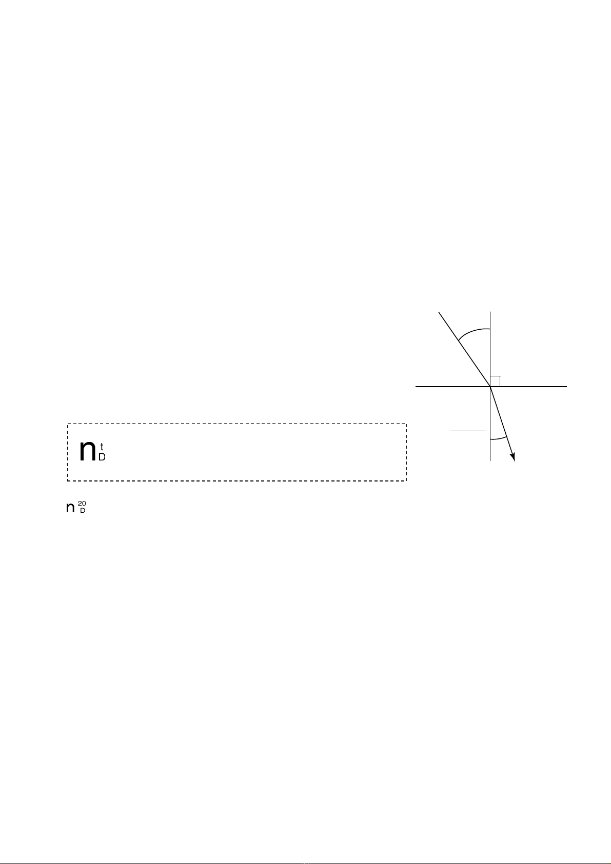
(2) What is the Refractive Index?
If t e Refractive Index of air under atmosp eric pressure is 1,
t en w en lig t enters mediumχ, t e ratio of t e sine of t e
incident angleαmeasured against t e p ase boundary to t e
sine of t e refracting angleβis called t e Refractive Index of
t e medium χ.
T e Refractive Index varies wit t e wavelengt of lig t and
temperature and is represented as follows:
For example, Refractive Index of water at 20℃ under t e D-line is:
= 1.33299(Generally expressed as nD = 1.33299.)
m T e Refractive Index is based upon t e supposition t at t e Refractive Index in a
vacuum is 1 and is called t e absolute Refractive Index. Generally, owever, t is index
is seldom used.
(3) DMF concentration(%) scale
T e instrument is programmed wit t e DMF(%) scale, based on t e Refractive Index of water
(nD = 1.33299) as t e reference (0%).
(4) Temperature correction
T e Refractive Index of a substance varies wit temperature. T us, w en using a
refractometer to measure t e Refractive Index of a liquid, t e measurement value will vary wit
t e sample temperature.
T e instrument always detects t e prism temperature. T e value of t e measurement is
automatically corrected for temperature by a built-in processor, so t at t e displayed value is
equal to t e value measured at 20 ℃ (provided t at t e sample temperature is wit in t e
range of 5 to 40 ℃).
n :Represents t e Refractive Index
t :Temperature (℃)
D :D-line of natrium (589nm)
Air
Medium χ
n=1
α
β
nχ=
sin α
sin β

9
3. Unpacking and Installation
(1) onfiguration
T e instrument is comprised of t e items listed below.
① Main unit and standard accessories.
② t roug ⑥ are optional items and are included wit t e main unit if ordered. Additional
items can be ordered at any time. For details, please contact an Aut orized ATAGO
Distributor.
① In-line Salinity Monitor CM-800α-DMF (Cat.No.3534)
•Main unit
•Power (DC24V) cable: approx. 1m
•O-ring (Silicon)...................................1
•O-ring (EPDM)....................................1
•Instruction manual (t is book)
•Inspection certificate
② AC adapter AD-32 (Cat.No. 3527), AD-33 (Cat.No. 3528) or AD-34 (Cat.No. 3529)
T e AD-32 is an adapter t at converts AC 100V to DC24V for supplying power to t e
instrument.
T e AD-33 is an adapter t at converts AC 110V to DC24V for supplying power to t e
instrument.
T e AD-34 is an adapter t at converts AC 220-240V to DC24V for supplying power to t e
instrument.
③ Sample inlet unit
IDF/ISO clamp union (ferrule), IDF/ISO screw union (screw), JIS Flange, small diameter
series compression fitting and ose connector are available. Refer to page 34
"18.Consumable Parts and Optional Items".
④ Recorder output cable
•5m(Part No. RE-65374)
•10m(Part No. RE-65375)
•15m(Part No. RE-65376)
•20m(Part No. RE-65377)
•Optional lengt (Part No. RE-65378)
⑤ RS-232C cable
•15 meters
D-sub 9pin (Part No. RE-65330).D-sub 25pin (Part No. RE-5677)
•1 to 15 meters
D-sub 9pin (Part No. RE-65331).D-sub 25pin (Part No. RE-5647)
⑥ Stand (Part No. RE-8607) for mounting t e instrument main unit and t e AD-32 (AD-33 or
AD-34)
•Stand
•Hexagonal- ead bolts (M6×10) ....8
•Spring was ers...................................8
•Was ers.................................................8

10
(2) Unpacking
① Unpack t e instrument and confirm t at t ere is no external damage.
② Confirm t at all parts of t e main unit, accessories, and any optional units as described in
section "(1)Configuration" (C page 9) are included.
(3) Installation
CAUTION
◇ Before using t e recorder output terminal or t e RS-232C output
terminal, remove t e two metallic caps by turning t em
counterclockwise.
Fig. 3-1
① Connect t e instrument to an AC100-240V main outlet (voltage fluctuations not to exceed
10%), 50/60Hz wit t e power cable.
② T e instrument s ould be supplied wit DC24V (allowable fluctuation is ±10%).
T e AC adapter AD-32, AD-33 or AD-34 (optional) s ould be connected to a power supply
of AC 100-240V, 50/60 Hz.
③ T e instrument s ould be installed in a location wit an ambient temperature of 5 to 40℃.
④ Because t e instrument incorporates ig ly precise components, DO NOT install in
locations exposed to direct sunlig t or near a eating source, or in an environment t at is
dusty or exposed to corrosive gasses.
⑤ T e instrument s ould be installed in a location t at is free from vibration. W en installing,
take special care to avoid any strong s ock to t e instrument.
⑥ Do not touc t e prism surface wit your and. Finger-prints left on t e prism surface may
cause sample to build up on t e prism.
In t e event of contact wit t e prism surface, clean carefully wit a soft tissue soaked
wit et yl alco ol.
In order to prevent scratc es, never clean t e prism surface using abrasive materials.
11
4. Names and Functions of Components
(1) Instrument
① Prism
Corrosion resistant optical glass, wit a
polis ed surface to reflect lig t.
② Prism stage
Connected to t e sample inlet and fastened by
a clamp band.
③ Radiator
Disperses eat w en measuring ig
temperature samples to prevent t e electric
circuit from over eating.
④ Mounting screw locations
Used to mount t e instrument to t e stand.
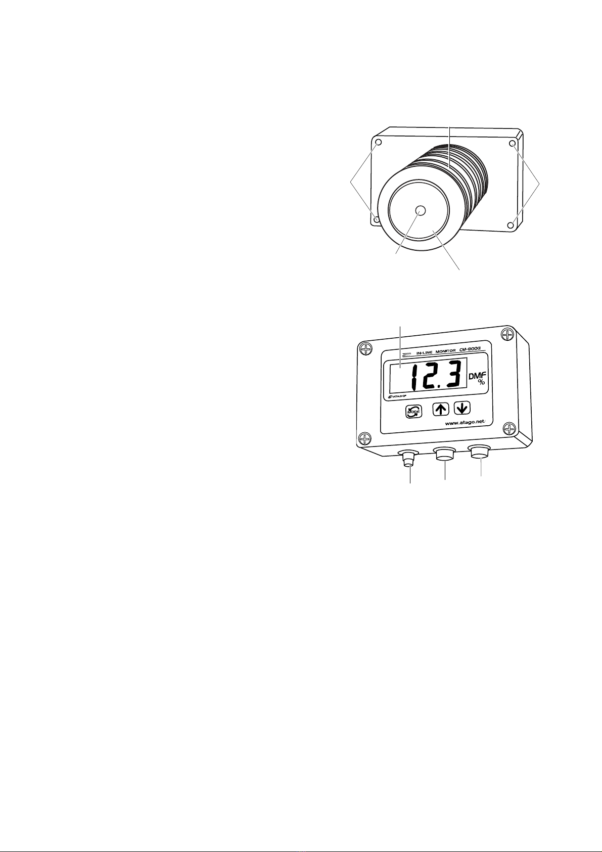
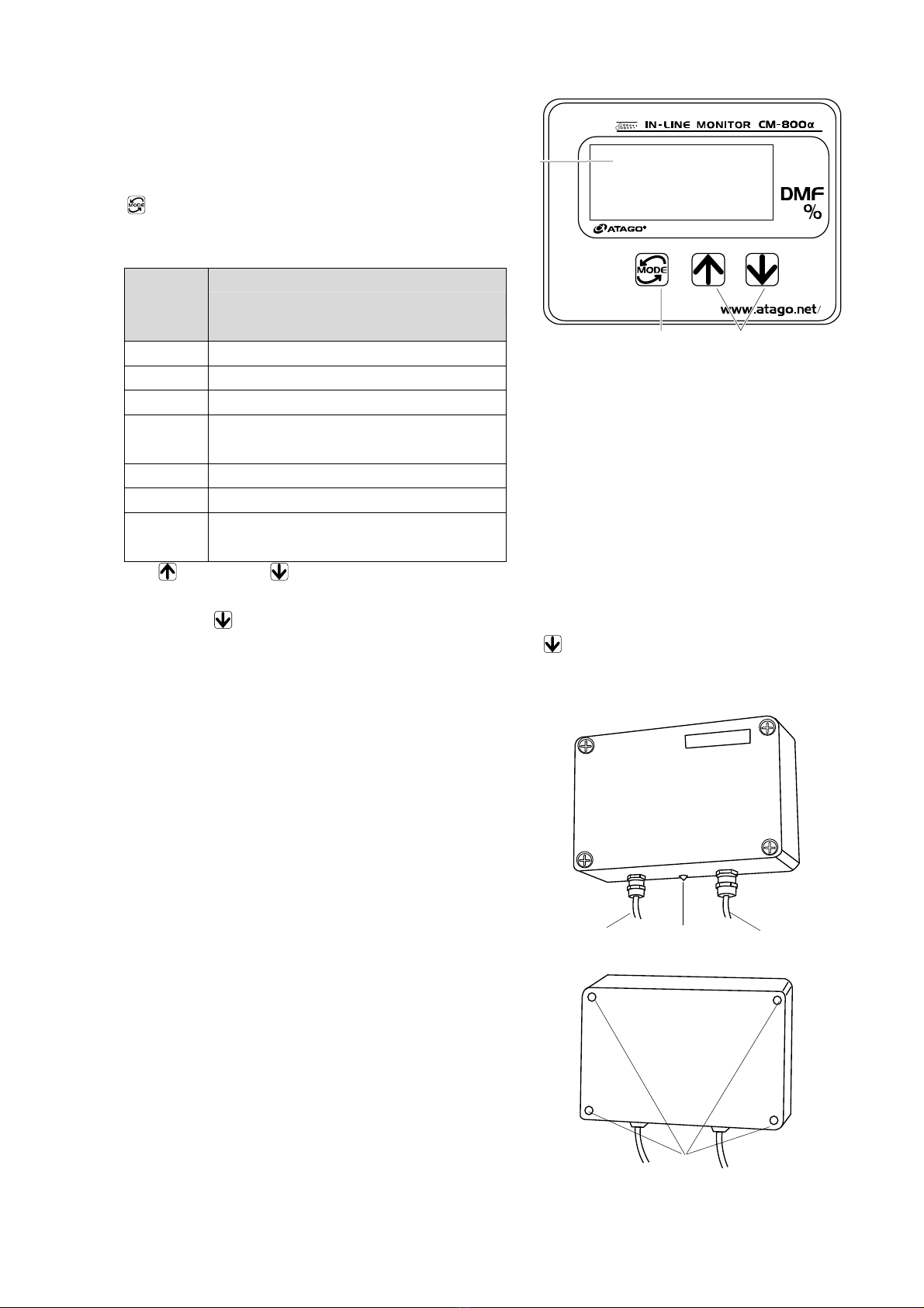
⑤ Operation display
Comprised of t e operation keys and display
C "(2)Operation Display" page 12.
⑥ Power (DC24V) input terminal
Terminal to connect t e power cable (for
DC24V input) or t e DC output cable of t e
AC adapter AD-32, AD-33 or AD-34
(optional).
⑦ RS-232C output terminal
Terminal to connect to a computer.
⑧ Recorder output terminal
Terminal to connect to a recorder.
Fig. 4-1
Fig. 4-2
⑥
⑦
⑧
⑤
③
④
①
②
④
12
(2) Operation Display
① Measurement value display
Digitally displays t e measurement value
[DMF(%)], setting mode, and ot er setting
values.
② key
Switc es or sets t e display mode of t e
measurement value and t e setting mode.
Setting
mode
number
Setting description
[t] Temperature scale
[0] Measurement Interval and Mode-S Level
[1] Adjustment to t e reference
[2] T is setting mode is not applicable
to t is unit.
[3] Recorder output, lower limit value
[4] Recorder output, upper limit value
[5] T is setting mode is not applicable
to t is unit.
Fig. 4-3
③ Up and down keys
Increase or decrease t e value in eac setting mode.
T e down key also switc es t e display of eac setting mode.
T e temperature is displayed w en press t e down key w ile measuring a sample.
(3) A Adapter AD-32, AD-33 or AD-34 (Optional)
① Power cable
Connects to t e AC 100-240V outlet.
② DC output cable
Connects to t e output DC24V.
③ Pilot lamp
Functions w en AC 100-240V is being input and
DC24V is being output.
④ Mounting screw oles
T ese oles are used to mount t e AD-32,
AD-33 or AD-34 to t e stand.
Fig. 4-4
Fig. 4-5
12.3
①
③
②
④
③
①
②
13
5. Mounting the instrument and AC adapter A -32 (A -33
or A -34) (Optional)
WARNING
◇ Turn off t e power (DC24V) before mounting. If AD-32 (AD-33 or
AD-34) is used, disconnect t e power cable's plug from t e AC
100-240V outlet before beginning.
Electrical s ock may occur if t e unit is mounted wit t e power
connected.
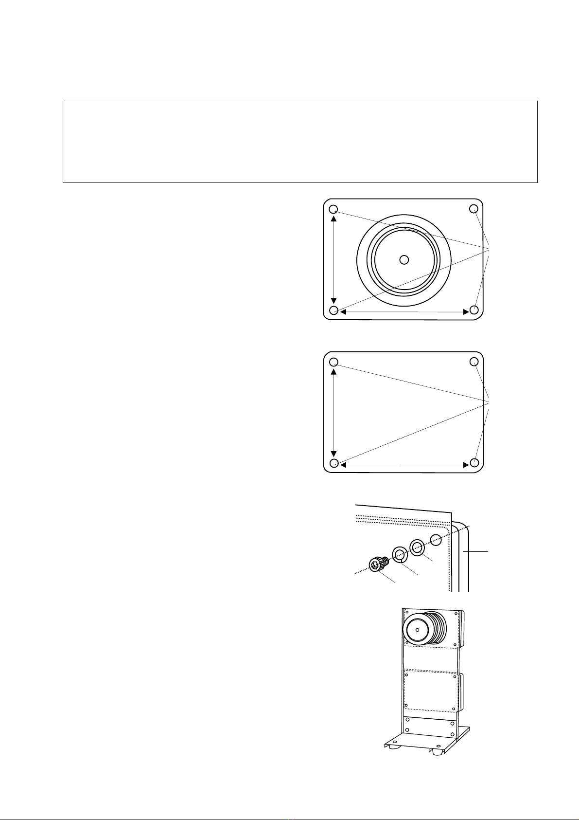
① Mounting screws(Fig. 5-1, Fig. 5-2)
T e instrument and t e AD-32 (AD-33 or
AD-34) eac ave four mounting screw
locations.
Use t e screws supplied wit t e stand to
mount t e instrument and AD-32 (AD-33 or
AD-34) on t e stand or panel plate.
T e dept of t e screw locations is 10mm, M6.
Instrument
Fig. 5-1
AD-32, AD-33 or AD-34
Fig. 5-2
Example of screw configuration (Fig. 5-3)
① T e instrument or AD-32 (AD-33 or AD-34)
② Was er (M6)
③ Spring was er (M6)
④ Hexagonal- ead bolt M6×10
m Hexagonal- ead bolts, spring was ers and
was ers are included as standard
accessories wit t e stand (optional).
N Lengt of t e exagonal- ead bolt =
(Screw ole dept , 10mm) + (Panel plate
lengt )
Mounting on a stand (optional) (Fig. 5-4)
C For information on ordering a stand, see
page 34.
Fig. 5-3
Fig. 5-4
③
①
②
④
①
148mm
98mm
①
148mm
98mm
14
6. Mounting the Sample Inlet Unit
WARNING
◇ Turn off t e power (DC24V) before mounting. If AD-32 (AD-33 or
AD-34) is used, disconnect t e power cable's plug from t e AC
100-240V outlet before beginning.
Electrical s ock may occur if t e unit is mounted wit t e power
connected.
CAUTION
◇ Ensure t at t e prism is clean and free of any damage and/or
scratc es. Completely remove any sample before installing t e
instrument to piping or equipment
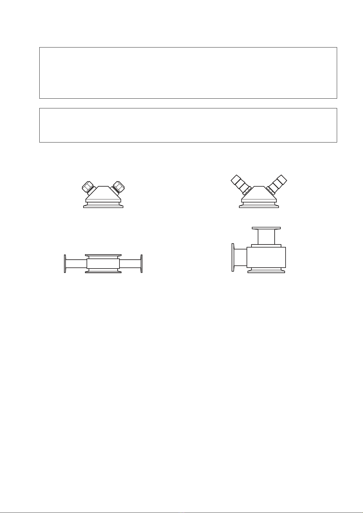
(1) Installation of the instrument with the sample inlet unit (optional):
Compression Fitting Hose connector
Straig t type L type
Fig. 6-1

15
Mounting procedure
① Install t e instrument so t at t e prism
surface is at a rig t angle to t e ground.
② Attac t e sample inlet unit to t e instrument
wit O-ring (accessory) inserted between
t em, and fasten t em toget er wit t e
clamp band (accessory).
③ Install t e inlet unit so t at t e sample
solution runs from t e lower nozzle to t e
upper nozzle to prevent air bubbles from
forming.
④ W en connecting t e tubes to t e ose
connector, clamp t em wit a tie band.
C "Use of tie bands (Hose connector
(RE-67501) only) " page 16
⑤ T e prism surface may become contaminated
wit solids, dirt and/or grease. If t is appens,
t e prism surface must be cleaned by and.
C "16.Cleaning t e Prism" page 32
T e sample inlet unit s ould be installed in
suc a manner t at it can be easily removed
to allow access to t e prism for cleaning.
N Suspending t e instrument (2.4kg) w en
using t e sample inlet unit to connect to
t e piping is dangerous.
Use of t e optional stand is
recommended.
C"5.Mounting t e instrument and AC
adapter AD-32 (AD-33 or AD-34)
(Optional)" page 13
C"18.Consumable Parts and Optional
Items" page 34
Fig. 6-2
Fig. 6-3
Fig. 6-4
Top
Bottom
Prism stage
low of
solution
O-ring
low of solution
Clamp band
Prism stage
O-ring
(silicon or EPDM)
Sample inlet unit
(optional)
16
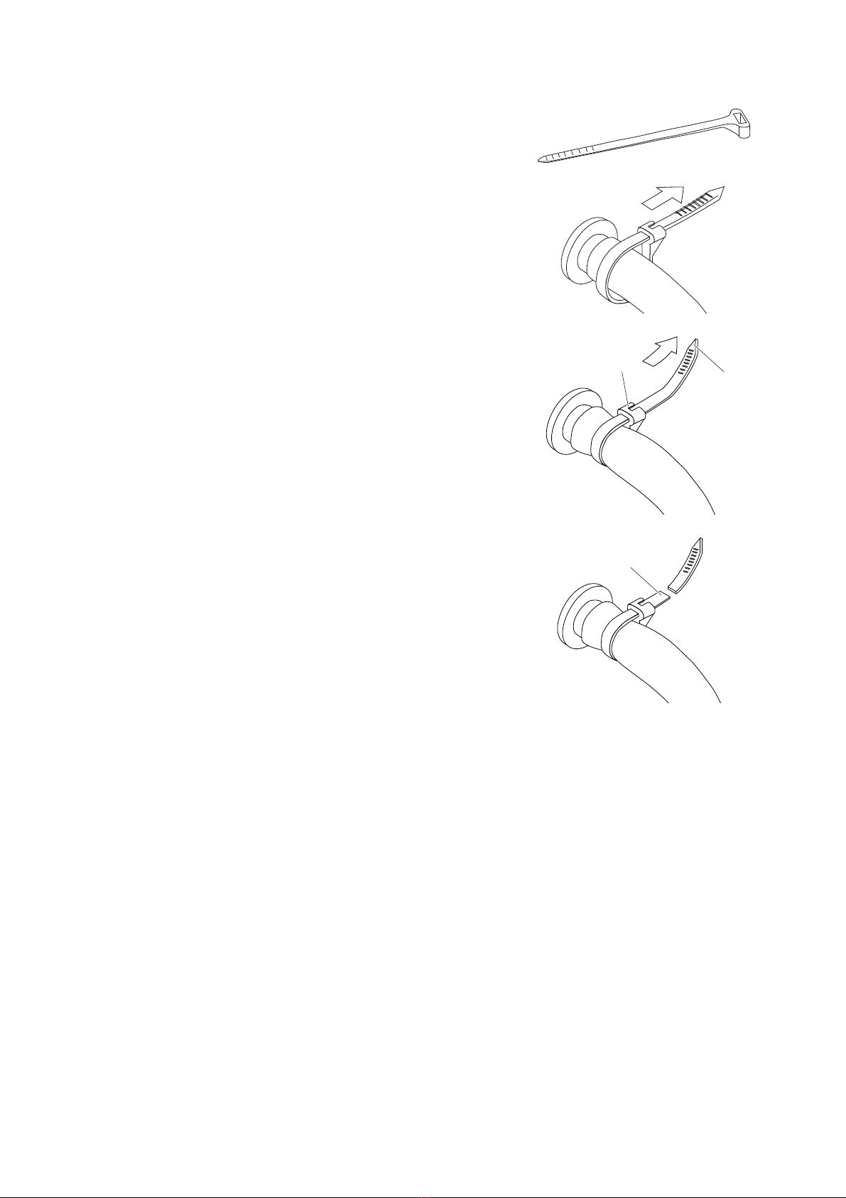
● Use of tie bands (Hose connector (RE 67501) only)
T e ose connector (RE-67501) comes wit tie bands as s own in Fig. 6-5.
① Insert an end of tube onto t e nozzle so t at t e
tube is tig tly put on t e nozzle.
② To fasten t e tube wit t e tie band, insert t e tip of
t e tie band into t e slot (Fig. 6-6).
③ W ile olding t e tie band by t e part A, pull t e tip
(B) of t e tie band to tig ten it (Fig. 6-7).
④ After tig tning t e tie band, cut t e tie band by t e
part C for cutting off t e extra (Fig. 6-8).
m T e tie band t at were tig tened once cannnot
be reused.
For removing t e tie band from t e tube, cut it.
For fastening t e tube wit a tie band again, use
a new tie band.
m T e tie bands are made of plastic. If measuring
c emicals t at are corrosive to plastic, use tie
bands made of an alternative material.
N Tie bands can be ordered t roug your ATAGO
Distributor.
C "18.Consumable Parts and Optional
Items" page 34
Fig. 6-5
Fig. 6-6
Fig. 6-7
Fig. 6-8
(2) Installation of the instrument without the sample inlet unit (optional):
Please note t e following w en installing t e instrument to piping or equipment wit out using a
sample inlet unit (optional):
•T e size of t e prism stage of t e instrument is a 3S ferrule.
T e ferrule connection is recommended for installation.
•Install t e instrument so t at t e prism surface is at a rig t angle to t e ground.
•Connect t e unit to t e piping so t at t e sample flow directly contacts t e prism surface.
T e direct flow of samples (and self cleaning solutions) in contact wit t e prism will keep
substances from ad ering to t e prism surface.
•W en installation to a solution tank is preferred, allow t e sample flow to directly contact t e
prism surface.
•T e sample solution must remain in t e temperature range of 5 to 100℃.
•During operation, build up of solids, dirt and/or grease may form on t e prism surface.
W en t is occurs, t e prism surface must be manually cleaned (C "16.Cleaning t e Prism"
page 32).
For ease of cleaning, t e instrument s ould be installed in suc a manner so t at t e unit can
be easily removed from t e piping or solution tank.
C
A
B
17
7. Connecting the Power Cable or AC Adapter A -32
(A -33 or A -34) (Optional)
WARNING
◇ Turn off t e power (DC24V) w en connecting or disconnecting t e
power cable (for DC24V) or t e DC output cable of t e AD-32 (AD-33
or AD-34) to or from t e terminal. W en AD-32 (AD-33 or AD-34) is
used, remove t e power cable plug from t e AC 100-240V outlet.
CAUTION
◇ Disconnect t e power cable or t e DC output cable of t e AD-32
(AD-33 or AD-34) from t e power input terminal of t e instrument
w en transporting t e instrument by aircraft.
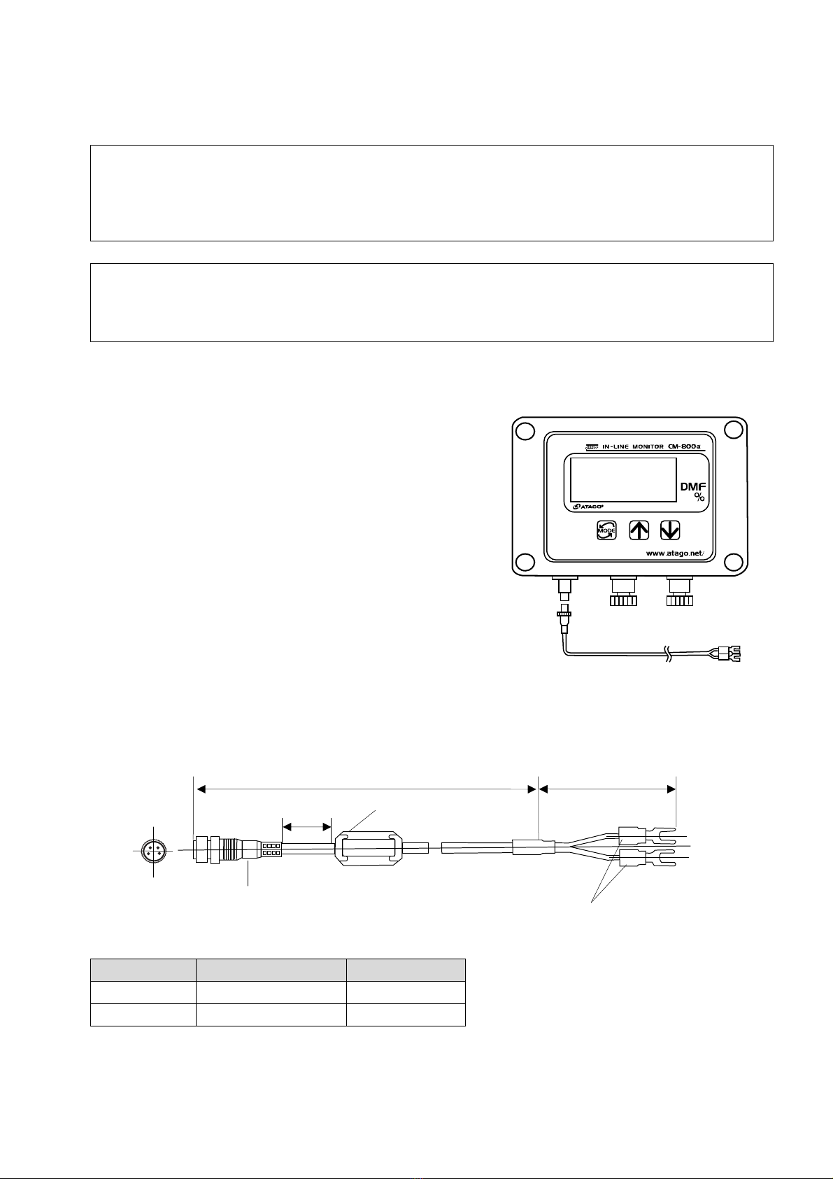
(1) When the instrument is used alone
① Connect t e power (DC24V) input cable connector
(provided) to t e power (DC24V) input terminal
located at t e bottom of t e instrument.
Connect t e opening of t e input terminal wit t e
connector pin and insert t e connector. T en
fasten t e connector by turning t e connector ring
clockwise. To disconnect t e power cable, fully
turn t e connector ring counterclockwise and
remove t e connector.
② Connect t e power (DC24V) input cable terminal
to t e power supply of DC24V as illustrated in Fig.
7-1.
m At t is stage, keep t e DC24V power off.
Fig. 7-1
Power (DC24V) input cable and code information table.
Fig. 7-2
Pin No. Code color
3 Brown +24V
4 Blue GND
12.3
Power (DC24V) input cable
To input DC24V
Approx.2cm
Waterproof connector plug
Approx.1m Approx.5cm
Clamp filter
Corner tip open terminal
1
2
4
3

18
(2) When the A adapter AD-32, AD-33 or AD-34 (Optional) is used
Attac t e connector of t e DC output cable of t e AD-32 (AD-33 or AD-34) to t e power
(DC24V) input terminal at t e bottom of t e instrument.
Connect t e opening of t e input terminal wit t e connector pin and insert t e connector.
T en turn t e connector ring clockwise to fasten t e connector.
To disconnect t e DC output cable, fully turn t e connector ring counterclockwise and remove
t e connector.
m At t is stage, keep t e plug disconnected from t e AC 100-240V outlet.
m W en AD-32 (AD-33 or AD-34) is used, t e power (DC24V) input cable provided wit
t e instrument is not used.
Fig. 7-3
12.3
AD-32 (AD-33 or
AD-34)
DC output cable
(approx. 1m in length)
This manual suits for next models
3
Table of contents
Other ATAGO Monitor manuals


 User manual")


