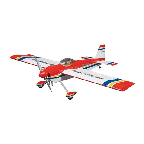
TBM P-40 User manual

TBM
P-40 ASSEMBLY MANUAL
The TBM P-40 was designed to be the best flying P-40 possible. Several minor changes were made to greatly
improve the low speed and high speed flight of the plane. We hope that you enjoy the wide speed range
capabilities, scale looks, and quick assembly.
The TBM P-40 has these advanced features:
-Cowl screws are completely hidden.
-Wing is 3 pieces for very easy assembly and transportation
-Wing panels held in place using a machine gun to completely hide the screw
-Canopy uses a hatch latch to conceal the air valve, pressure gauge, fuel dot and switches.
-Optional spinner is CF, painted in Olive Drab or Red.
-Optional muffler for DA-85 is available.
-Ailerons and Flaps are properly hinged at the factory.
IMPORTANT ASPECTS TO KEEP IN MIND
-The plane is not tail heavy like most warbirds. We moved the wing back and lengthened the nose, so the
batteries don’t have to be strapped to the engine along with 5 lbs of lead. Mount the batteries last, and
put them where necessary for CG reasons. We put our batteries as shown in the photos as follow.
-The plane does not required lots of downthrust like most warbirds. The airfoil is much more
symmetrical, so it does not generate lots of asymmetric lift. We have no downthrust in the engine.

-The plane is very light compared to other warbirds of this size. It is as much as 10 lbs lighter, so take
offs and landings are much easier. Don’t fly it in with flaps at 30 mph. With flaps, it is stable at almost
walking speed.
-While it can torque roll and hover, it is not an aerobatic plane with giant stabs and rudder, with a thick
wing and a giant diameter prop. It will take more time to recover from 3D maneuvers, so don’t push it
close to the ground until you are very familiar with it.
-You need access to the cowl screws and wing bolts after you install all the equipment. Keep checking
that you can get your hand and tools to these screws. Don’t mount a battery pack or something right in
the way.
-Make the fuel tank easily removable with Velcro so you can move the tank out of the way so as to get
your hands into the front of the fuselage for maintenance reasons.
-Most everything is hidden from view under the canopy. This includes the fuel dot, air fill valve for the
retracts, air pressure gauge, cowl screws, wing bolts, Rx switch and ignition switch. Don’t cut any holes
into the airframe for this stuff! The hatch pops off with a single latch for easy access to these items to
keep the plane neat and clean.
-The plane is made to stay on the gear will the servos extensions in the fuselage and the air lines all
connected permanently. Try to leave the center section of the wing on the plane permanently so you
don’t have to mess with these connections all the time. All you need to do is plug in the ailerons and
install the wing tips which is a 2 minute job.
INCLUDED WITH THE KIT:
Be sure to inventory all the parts
-3 piece wing
-Fuselage
-Canopy
-Fuel tank
-Fuel line
-(4) ¼-20 blind nuts, 2” 1/4-20 bolts, ¼-20 locknuts, ¼-20 washers for engine
-All servo arms, horns, cable and clevis. (The servo arms require metal servo wheels or Air Wild unihubs
to attach to).
COMPONENTS NEEDED TO COMPLETE THE KIT
Be sure to have all the parts on hand to hasten installation
-DA-85 with special hidden muffler is the engine of choice. Many other engines will work well, from
50cc up to 85cc. A Zenoah G-62 offers great power.
-Propeller: a three blade is scale. A Menx 24x14 is a good high speed 2-blade for an 80-85cc engine.
-We offer the proper 6” spinner in either red or olive drab color
-two Sullivan #562 4-40 snap links for choke and throttle
-two Sullivan #584 graphite push rods
-two Hitec HS225 servos for choke and throttle
-seven metal servo wheels to use included servo arms, or metal servo arms.
-Seven high torque metal gear servos. We use Hitec HS-7955 for the highest performance, though Hitec
HS-645 servos work OK for general flying.
-Six 1.25” MPI metal servo arms. This offers the proper amount of throw and torque as well as being
long enough to exit the servo hatch properly.
-Y-harnesses for the ailerons and flaps and elevators depending on your receiver. It is much easier to set
up if each servo is on its own channel, though you can use Y-harnesses if necessary.
-Two 2’ servo extensions which stay inside the center section of the wing for the ailerons if you do not
use a Y-harness. Use two 12” extensions with a 12” Y harness if you prefer.
-Two 3’ servo extensions for the elevators. Use a single 2’ extension with a Y-harness if you prefer.
-Two 6” servo extensions which connect to the ailerons and remain in the outer wing panels. These
connect to the servo extensions in the center wing panel.

-We recommend a package of servo wire holders
-Landing gear and tailwheel. TBM has these specially made for the P-40.
-Fuel overflow bulkhead type fitting
-Batteries – one for ignition and two for Rx are recommended. Three 2600 mah batteries will offer 10
flights. You may need regulators.
-Switches for the Rx and ignition.
-A few feet of fuel line
-Loctite!
ASSEMBLY SEQUENCE
PLEASE FOLLOW THE ORDER AS FOLLOWS FOR THE EASIEST INSTALLATION
QUICK OVERVIEW
1) Rx, switches and temporarily mount a battery.
2) Rudder and tailwheel
3) Engine
4) Muffler
5) Throttle and Choke servos
6) Fuel tank
7) Landing gear
8) Wing servos
9) Stabs
10)Cowl
11)Canopy
12)Spinner
13)Batteries
1) In order to set up your servos and retract valve, you need the Rx, switch(s) and battery installed. Put
them where shown in the photos below. Later you should mount the 2 Rx batteries where necessary for
balance.

2) Rudder (NOTE – both the rudder and tailwheel cables are crossed)
a. Install rudder horn using Hysol
b. Glue rudder in place using Hysol
c. Install ball links in outer holes (3” spread).
d. Install pull-pull cable. Use the centered ball link, not the offset ball link (look at the way that the
brass ball is machined and you will see a difference). Loop the cable through the terminator, then
use heat shrink tubing.
e. Install the cables to the retractable tailwheel assembly. It may be necessary to remove the
tailwheel assembly from the airplane. Connect the cables to the servo arm.
f. Before installing the rudder servo (Hitec HS-7955 for highest performance), install the included
servo arm or use aftermarket servo arm (SWB 3” is recommended). Install 4 ball links for the
rudder and tailwheel steering as shown in photo. Use the outside holes on the servo arm for the
rudder and the inside servo holes for the tailwheel steering. Then install servo.
g. Connect the cables by pulling the cables taught, and marking them where they should pass
through the terminator. Using a felt tip pen, mark the cable itself. Then disconnect the cable from
the rudder and tailwheel steering arm. Then terminate the cables. Then reinstall and adjust as
necessary.
In the photo below, note that there are 2 holes in the top of the wing, under the fuselage, where the air lines and
flap and aileron servo extensions enter the cockpit area. Note we have only airlines going through the left hole,
and airlines and both the flap and aileron extensions on the right hole (close to the Rx).
Note placement of air fill valve and pressure gauge.

3) Engine
a. Install the Sullivan #562 ball links to the choke and throttle arm of the DA-85 engine.
b. Use the DA-85 template to drill 4 ¼” mounting holes
c. Use provided bolts, blind nuts, washers and locknuts to install engine. Blind nuts alone are not
strong enough to hold gas engines of any size.

d.
e. Drill a ¾” hole for the ignition wires in the right side of the motor box. Put the ignition lead
through this hole and connect to the sparkplug.
f. Connect a battery, switch and regulator to the ignition, then install the ignition using Velcro.
Mount all these items inside the fuselage as far forward as possible. Mount the switch in the
“dash board” of the fuselage (not in the canopy) as shown. It is next to the fuel dot in the
following photo.
g. Use TBM spiral wrap to protect the ignition wires passing through the fuselage.

4) Muffler
a. Install to the engine and to the fuselage.
b. Reinforce the inside of the fuselage by gluing a 2” diameter disk of 1/8” plywood in place. First
mount the muffler, then drill a hole for a 10-32 screw. Then install the plywood. Then install a
blind nut. Without securing the muffler in some way, the muffler will break in a variety of
places.
In the photo above note the TBM overflow fitting installed. It is a brass bulkhead fitting in the right
side of the photo. This is for the overflow of the fuel when filling the plane. In this position, it is
hidden from view by the cowl, but still accessible. Be sure to put the cowl in place before installing
this part to be sure that there is no interference.

It’s a crazy looking muffler, but it is the best we could do. We wanted to keep the cowl as scale as
possible, and this muffler shape requires no cutting into the cowl. This muffler does not reduce rpm
much, and it is very loud. If you require it to be quieter, we have closed the ends of the exhaust
stacks by bending them inwards as is done on Sullivan mufflers. This definitely helps reduce noise,
but also lowers top rpm if you make the openings very small. Just experiment a little.
In the photos below you will see two 2600 mah LiIon battery packs for the Rx on the left side held in
via Velcro. In the center behind the fuel tank is the Rx. On the right is the Rx switch. The MPI
regulator is under the switch held in with red Velcro. This set up allows easy access to the wing
bolts.

5) Throttle and Choke servos
a. Install the #562 ball link to the Sullivan #584 push rod
b. Install two Hitec HS 225 servos as shown with arms pointed down.
c. Connect throttle and choke linkage. Make stand offs to hold the linkages using scrap wood if
necessary. You can see the stand offs in the photos.

Note in the photo above that there is plenty of room to access the screws which hold on the cowl and the screws
which hold on the wing. Keep this in mind through the building process. It is important to have easy access to
these screws. Keep items clear of these areas. Due to the necessary clearances, we mount the fuel tank, Rx, and
other items as shown.
6) Fuel tank
a. Mount the tank where shown and hold in with Velcro. See photos above. Make sure the tank is
easily removed, so leave extra fuel line in the plane so that you can pull the tank out of the way
without disconnecting fuel lines. The fuel dot is mounted in the “dash board” area. Be sure that
the line is long enough to reach outside the plane so that you don’t drip gas inside the plane.
7) Landing gear
a. Overview – if you are unfamiliar with landing gear, here is how it works. Basically you have 2
air tanks which use a T to connect them so they act like one tank. They are filled using a bicycle
type pump to 100 psi. We offer an electric hand held pump that looks like a portable drill which
has its own air gauge with works great. You should have an on board air gauge so that you can
be sure that the pressure is holding properly. There are a hundred places that the air can leak
from. You must fill the tanks and watch the gauge, if the pressure is the same for a few minutes,
then retract the gear, and check again in a few minutes. It’s bad news when they leak in the up
position and not the down position and you don’t realize it until you are flying. Then hook up the
air using T’s so all 3 gear go up or down together. You should mark the lines and use quick
connects where necessary to remove the center section of the wing. See the photos.
b. Tighten the nuts which hold the tires onto the axles. The nuts should stop on the collar of the axle
and should not prevent the tires from rotating. If the nuts do bind on the brass bushings, grind the
brass bushings down so that the tires will always turn freely. When satisfied with the fit, use
strong threadlock to lock the nuts in place.
NOTE – landing gear is not your friend. ¾ of all the OOPPPs videos of airplane crashes have to do with landing
gear failures. They are the most difficult part to keep operating of any RC component. They are delicate and
complicated but must take a lot of abuse. Not a good combination. If you never had retracts on a plane before
you are a happier person. Keep a close watch on these things. Cycle them before each flight. Check for binding
or loose parts. Be sure the tires are lined up properly. If the springs are too weak in the shock absorbers, replace
the spring or add a spring or a spacer. Watch that air gauge. Never ever trust them. They are out to get you.
Always have a plan if the gear doesn’t work. If your engine quits at a bad time, know what you are going to do

ahead of time. You can land gear up or gear down. If you have a choice of landing on grass or on pavement,
then decide before you take off which you will land on in case of landing gear failure. My preference is landing
gear up on grass if the engine fails and the landing is going to be ugly no matter what. If the gear fails up in the
air, and I can choose where to land, I like the grass better than pavement, though either way won’t be good for
the cowl, the asphalt is hard on the fuselage and wings. I never retract the landing gear on a maiden flight, I
leave that for a maiden flight of its own. If you go to church, pray for your gear to work.
8) Wing Servos
a. Install the servos using metal servo arms as shown.
b. Glue in the horns using Hysol. Be sure to note that the flap horns and the aileron horns are not
put in the same place. The flap horns are mounted well behind the hinge line, while the aileron
horns are closer to the hinge line.
c. The ailerons need about 15 degrees of deflection, the flaps need as much as you can reasonably
get.
d. Connect the linkages as shown.
e. The aileron servo wires are held in place with wire keepers.
This photo shows the position of the flap horn. It is in the up position here.

This photo shows the aileron servo extension held in place with a blue wire keeper. Note the aileron horn. The
machine gun is shown. This is opposite of the production plane. The wing spar is glued into the wing tips on the
production model. This keeps the width of the center wing smaller for easier transportation.
9) Glue in the wing spars.
a. Trial fit everything. Then glue the spars into the outer wing sections using Hysol. Install the wing
onto the plane to let the glue harden so that it lines up properly.
10)Stabs
a. Install the servos and horns like the ailerons. Slip them onto the tube, and screw in place.
b. I prefer to use 3’ servo extensions so that the servo extensions can hang out of the back of the
fuselage when the stabs are removed.
11)Cowl
a. Just install the 6 screws which hold on the cowl. Use locktite.

12)Hatch
a. You may want to add a pilot, and install the included instrument panel. Be sure that the hatch
latch functions properly.
13)Batteries
a. Now install the batteries to make the plane balance properly. The CG is located just in front of
the wing spar. Just separate the wing tip from the wing center section enough to get one finger
onto the center section of the wing, just in front of the spar and lift.
14)Set up
a. Like most warbirds, if you fly it like a warbird, you don’t need much throw. 15 to 20 degrees on
all the surfaces is fine except for the flaps which you should get as much as practical. If you are
going to 3D the plane you will need digital servos, and as much throw as possible. This plane flat

spins better than any aerobatic plane. It spins like a top and doesn’t lose altitude. Just try it a little
higher up than I did because it takes just a little longer to come out than you think.
15)Flying
a. All warbirds and many other planes veer hard to the left on take off. This plane is no exception.
As you go to full throttle, put in right rudder!
b. I prefer to take off with partial flaps. This gets the plane into the air more quickly.
c. I land with full flaps at a very slow pace. You must add throttle with flaps. As soon as you touch
down, I recommend that you retract the flaps because the tail of the plane will come down right
away and make it easier to control. With the flaps extended, the tail will stay up in the air longer.
d. On one of the first flights, fly the plane inverted. The plane should slowly descend if the CG is
correct. If the plane climbs, add weight to the nose.
e. We did not remove all the dihedral, so the plane rolls in the direction of the rudder. Right rudder
makes the plane roll to the right. Also, right or left rudder causes the plane to pull down towards
the landing gear. If you are an aerobatic pilot you will be used to this. I suggest that you use your
computer radio to mix in opposite aileron to rudder and also to mix up elevator to rudder so that
using the rudder offers more yaw and less of the other.
f. We have flown this plane straight down at full throttle with a DA-85 with a 20x16 prop and have
gone over 160mph. If you do this, don’t aim at any people, and don’t pull too many G’s! If a
servo, servo linkage, control horn, or whatever stops working, it could be a serious problem.
g. If you fly in fun scale, there are many photos of these planes in full scale available on the
internet.
h. While the original model would hover and torque roll, we changed the hinging to be more scale.
The flight envelope is more scale as well.
Table of contents
Other TBM Toy manuals
Popular Toy manuals by other brands

Enabling Devices
Enabling Devices Smooth Moves Sloth user guide

Eduard
Eduard Ju 88C-6b Night Fighter exterior quick start guide
SYMA
SYMA S100 Instructions for use

Innovative Hobby Supply
Innovative Hobby Supply Clock Tower BK 6425 General assembly instructions
REVELL
REVELL Supermarine Spitfire Mk.XVI Assembly manual

Lionel
Lionel Metro-North Railroad 25th Anniversary M-7 Commuter Train... owner's manual
