402.2006 TR10B005 RE
Sehr geehrter Kunde,
wir freuen uns, dass Sie sich für ein Qualitäts-Produkt aus
unserem Hause entschieden haben. Bitte bewahren Sie diese
Anleitung sorgfältig auf!
Lesen und beachten Sie diese Anleitung, in ihr stehen wichtige
Informationen für den Einbau, den Betrieb und die korrekte
Pflege / artung des Garagentor-Antriebes, damit Sie über
viele Jahre Freude an diesem Produkt haben.
Beachten Sie bitte alle unsere Sicherheits- und arnhinweise,
die mit ACHTUNG bzw. Hinweis besonders gekennzeichnet
sind.
1 W CHT GE H NWE SE
ACHTUNG
Die Montage, artung, Reparaturen und
Demontage des Garagentor-Antriebes soll
durch Sachkundige ausgeführt werden.
Hinweis
Dem Endverbraucher müssen das Prüfbuch und die
Anleitung für die sichere Nutzung und artung der
Toranlage zur Verfügung gestellt werden.
1.1 Wichtige Sicherheitsinformationen
ACHTUNG
Eine falsche Montage bzw. eine falsche Hand-
habung des Antriebes kann zu ernsthaften
Verletzungen führen. Aus diesem Grund sind
alle Anweisungen zu befolgen, die in dieser
Anleitung enthalten sind.
Der Garagentorantrieb ist ausschließlich für den
Impuls- Betrieb von federausgleichenden Schwing-
und Sectionaltoren im nichtgewerblichen Bereich
vorgesehen. Der Einsatz im gewerblichen Bereich
ist nicht zulässig!
Beachten Sie bitte die Herstellerangaben betreffend der
Kombination Tor und Antrieb. Mögliche Gefährdungen
im Sinne der EN 12604 und EN 12453 werden durch
die Konstruktion und Montage nach unseren Vorgaben
vermieden. Toranlagen, die sich im öffentlichen Bereich
befinden und nur über eine Schutzeinrichtung, z.B.
Kraftbegrenzung verfügen, dürfen nur unter Aufsicht
betrieben werden.
1.1.1 Gewährleistung
ir sind von der Gewährleistung und der Produkthaftung
befreit, wenn ohne unsere vorherige Zustimmung eigene
bauliche Veränderungen vorgenommen oder unsach-
gemäße Installationen gegen unsere vorgegebenen
Montagerichtlinien ausgeführt bzw. veranlasst werden.
eiterhin übernehmen wir keine Verantwortung für den
versehentlichen oder unachtsamen Betrieb des Antriebes
und des Zubehörs sowie für die unsachgemäße artung
des Tores und dessen Gewichtsausgleich. Batterien und
Glühlampen sind ebenfalls von den Gewährleistungsan-
sprüchen ausgenommen.
Hinweis
Bei Versagen des Garagentor-Antriebes ist unmittelbar ein
Sachkundiger mit der Prüfung/Reparatur zu beauftragen.
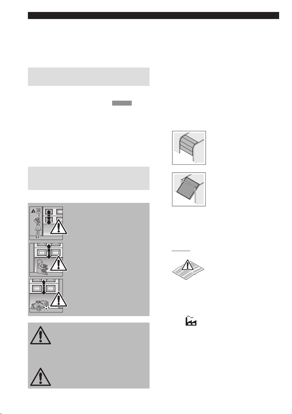
1.1.2 Überprüfung des Tores / der Toranlage
Die Konstruktion des Antriebes ist nicht für den Betrieb
schwerer Tore, das heißt Tore, die nicht mehr oder nur
schwer von Hand geöffnet oder geschlossen werden
können, ausgelegt. Aus diesem Grund ist es not-
wendig, vor der Antriebsmontage das Tor zu über-
prüfen und sicherzustellen, dass es auch von Hand
leicht zu bedienen ist.
Hierzu heben Sie das Tor ca. einen Meter an und lassen
es los. Das Tor sollte in dieser Stellung stehen bleiben
und sich weder nach unten noch nach oben bewegen.
Bewegt sich das Tor doch in eine der beiden Richtungen,
so besteht die Gefahr, dass die Ausgleichsfedern nicht
richtig eingestellt oder defekt sind. In diesem Fall ist mit
einer erhöhten Abnutzung und Fehlfunktionen der Tor-
anlage zu rechnen.
ACHTUNG: Lebensgefahr!
Versuchen Sie nicht, die Ausgleichsfedern für
den Gewichtsausgleich des Tores oder deren
Halterungen selbst auszuwechseln, nachzustellen,
zu reparieren oder zu versetzen. Sie stehen unter
großer Spannung und können ernsthafte Ver-
letzungen verursachen. Kontrollieren Sie außer-
dem die gesamte Toranlage (Gelenke, Lager
des Tores, Seile, Federn und Befestigungsteile)
auf Verschleiß und eventuelle Beschädigungen.
Prüfen Sie, ob Rost, Korrosion oder Risse vor-
handen sind. Die Toranlage ist nicht zu benutzen,
wenn Reparatur- oder Einstellarbeiten durchge-
führt werden müssen, denn ein Fehler in der
Toranlage oder ein falsch ausgerichtetes Tor
kann ebenfalls zu schweren Verletzungen führen.
Hinweis
Bevor Sie den Antrieb installieren, lassen Sie zu Ihrer
eigenen Sicherheit Arbeiten an den Ausgleichsfedern
des Tores und falls erforderlich, artungs- und Reparatur-
arbeiten nur durch einen qualifizierten Garagentor-Kunden-
dienst ausführen! Nur die korrekte Montage und artung
durch einen kompetenten / sachkundigen Betrieb oder eine
kompetente / sachkundige Person in Übereinstimmung mit
den Anleitungen kann die sichere und vorgesehene
Funktionsweise einer Montage sicherstellen.
1.2 Wichtige Anweisungen für eine sichere Montage
Der Sachkundige hat darauf zu achten, dass bei der
Durchführung der Montagearbeiten die geltenden Vor-
schriften zur Arbeitssicherheit sowie die Vorschriften für
den Betrieb von elektrischen Geräten zu befolgen sind.
Hierbei sind die nationalen Richtlinien zu beachten.
Mögliche Gefährdungen im Sinne der DIN EN 13241-1
werden durch die Konstruktion und Montage nach
unseren Vorgaben vermieden. Der eiterverarbeiter hat
darauf zu achten, dass die nationalen Vorschriften für den
Betrieb von elektrischen Geräten eingehalten werden.
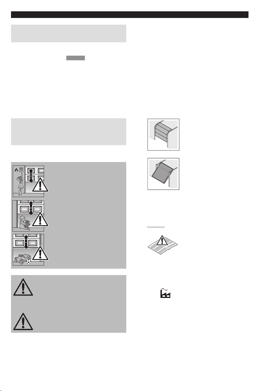
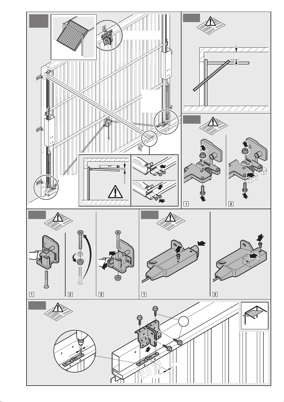
1.2.1 Vor der Montage des Garagentor-Antriebes ist zu über-
prüfen, ob sich das Tor mechanisch in einem fehlerfreien
Zustand und im Gleichgewicht befindet, so dass es auch
von Hand leicht zu bedienen ist. (EN 12604). eiterhin
ist zu prüfen, ob sich das Tor richtig öffnen und schließen
lässt (siehe Kapitel 1.1.2).
Außerdem sind die mechanischen Verriegelungen des
Tores, die nicht für eine Betätigung mit einem Garagentor-
Antrieb benötigt werden, außer Betrieb zu setzen. Hierzu
zählen insbesondere die Verriegelungsmechanismen des
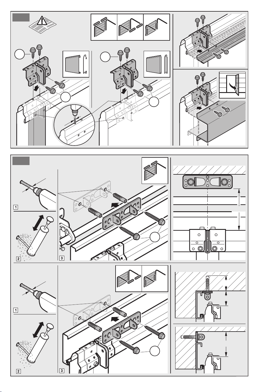
Torschlosses (siehe Kapitel 3.2.1/3.2.2). ➤
DEUTSCH