TBS GEMINI Mini FPV Hex User manual

TBS GEMINI Mini
FPV Hex
Miniature hexacopter for fast
FPV flight and multirotor racing
Revision 2014-12-02
The TBS GEMINI is the latest generation of
mini racer multirotors. Its revolutionary
design with forward tilting motors and
aerodynamic canopy as well as fully
integrated yet modular electronics turn it into a beast that will dominate any race event.
Optimize your setup for HD filming with a Mobius or as the ultimate racer. Both setups are capable of
operating on 3S and 4S setups, depending on your skill level and speed requirements. It is versatile enough
to become your take-anywhere, fly-anytime multi rotor and at the same time rip through trees and leave the
competition in the dust at races.
The frame is based on a design by award-winning pilot and one of the leading innovators in multi rotor
design, William Thielicke (aka Shrediquette). TBS added its own secret-sauce with a fully-modular, crash
friendly ESC and flight control installation. We get the best of both worlds: a tightly integrated component
layout that optimizes weight efficiency, but also repair-friendliness in case of crashes. And let's face it, these
things are made for crashing.
Assembly takes a few minutes as you add props, choose between the race and film setup and secure the
canopy. A full slew of spare parts are available to repair the hex after a crash.
Key features
•Aerodynamic canopy for stability in forward-flight
•Forward-tilting motors for efficient, high speed flight
•Built-in FPV camera
•Optional Mobius HD camera (film canopy)
•CORE OSD/power supply with integrated current sensor
•Ready for long range FPV
•Stacked modular TBS 4A ESCs
• High-quality T-motors with vibration dampening
• 4-inch propellers
•TauLabs Quanton-based flight control
•Crash-friendly, yet integrated layout
1

Before we begin
Thank you for buying a TBS product! The TBS GEMINI is a new racing multirotor aircraft from Team
BlackSheep (TBS). It features the best design practices available on the market to date, providing a great
flying experience and incredible FPV characteristics.
Please read this manual carefully before assembling and flying your new TBS GEMINI hexacopter. Keep this
manual for future reference regarding tuning and maintenance.
Disclaimer
Our request to you; the aircraft may not be used to infringe on people's right to privacy. We have designed a
toy with mind blowing capabilities. It is your responsibility to use it reasonably and according to your
experience level. Use common sense. Fly safe. You are on your own. TBS has no liability for use of this
aircraft.
●Locate an appropriate flying location
●Obtain the assistance of an experienced pilot
●Practice safe and responsible operation
●Always be aware of the rotating blades
●Prevent moisture
●Keep away from heat or excessive amounts of sunlight
2

Specifications
Type:
FPV racer hexacopter
Power:
3S 1700mAh or 4S 1050mAh Lithium-ion Polymer battery, JST-connector
Motors:
6x 1806 class, 2100kV, 96W, 22x22 mm mount, M4 shaft, 10° forward tilt
Propellers:
6x 4x4.5-inch, 2-blade propellers (3xCW, 3xCCW)
Speed controllers:
TBS 4A Bulletproof ESCs, stacked modular configuration
Flight controller:
TBS COLIBRI flight controller, powered by TauLab codebase
RC receiver:
5-channel minimum, PPM, S-BUS, D-BUS or PWM
FPV camera:
32x32mm board camera, 2.8 mm lens, TBS CHIPCHIP V2
FPV transmitter:
TBS 2.4 Ghz or 5.8 GHz A/V transmitter, TBS UNIFY 5G8 200mW
HD camera:
Mobius HD ActionCam (available separately), vibration dampened
Canopy:
Racing (aerodynamic, light) or Film (protects camera, extra battery space)
Flight time:
Approx. 10 minutes
Speed:
Max. speed 80 km/h
Distance:
up to 2km range (and return)
Working temperature:
0 - 40°C
Size:
315 mm / 8.5-inch, diagonally
Battery spec:
25C+, max. 48(W) x 70(L) x 19(H) mm, 110 grams
All-up-weight:
340 to 370 grams, fully loaded
Kit contents:
(base kit)
1x Assembled TBS GEMINI main frame
6x TBS BULLETPROOF 4A ESCs
1x TBS COLIBRI Flight controller
1x TBS CORE PNP25, pre-configured
1x TBS CHIPCHIP V2 camera
1x TBS UNIFY 5G8 200mW video transmitter
1x TBS 3S 1700 mAh LiPo battery
1x Racing camera mount
1x Racing VTX mount
1x VTX extension antenna holder
1x Racing canopy set
1x Film canopy set
1x Bag of light-weight nylon motor screws
6x TBS T-motor 2100kV Brushless motors
8x 4x4.5-inch propellers with adapter rings (4 pairs)
3

The TBS GEMINI
On the GEMINI hexacopter, the motors are tilted 10° forward in order to decrease the angle of attack of the
body in forward flight. The whole arm is deformed in order to achieve the desired forward tilt. This
decreases the net aerodynamic drag in fast translational flight. In a hover the body will lean backwards but it
will level out as it moves into forward flight. Additionally, the canopies help to reduce the drag coefficient of
the copter. The effects has been measured in a wind tunnel using a two-axes force balance, and the results
show that the drag is reduced by something around 30%.
The handling of the copter is not affected as long as the IMU is aligned parallel to the propellers (you can also
rotate the IMU by software via calibration).
The flight controller is based on the TauLabs Quanton platform and TBS contributes back to the project. The
controller has two modes. In "stabilize" mode (angle control) is auto levels and stabilized itself in flight, while
in "heading hold" (angular velocity control) it will stay in a particular angle until the pilot makes corrections,
very much like “manual” mode. There are a lot of other interesting features.
The TBS GEMINI has a two part canopy with a larger volume. This allows for using large batteries, a broader
range of video transmitters and larger receivers (hence people can install the gear they want). We selected to
include some very nice and light custom T-motors, these are made to precision with high quality bearings.
The ESCs were also developed specially for the GEMINI. They are located centrally on the frame in a stacked
rib formation for cooling and easy access. There are no LEDs on the canopy as of writing, but LEDs can easily
be added to facilitate LOS flight.
Maybe one of the most important factors is the 3S to 4S capability. The ESCs are able to handle both with
ease to cater for long fight time or high speed. When using the custom TBS ESCs on 4S, expect an
exceptionally fast forward flight and a rocket in ascend.
4
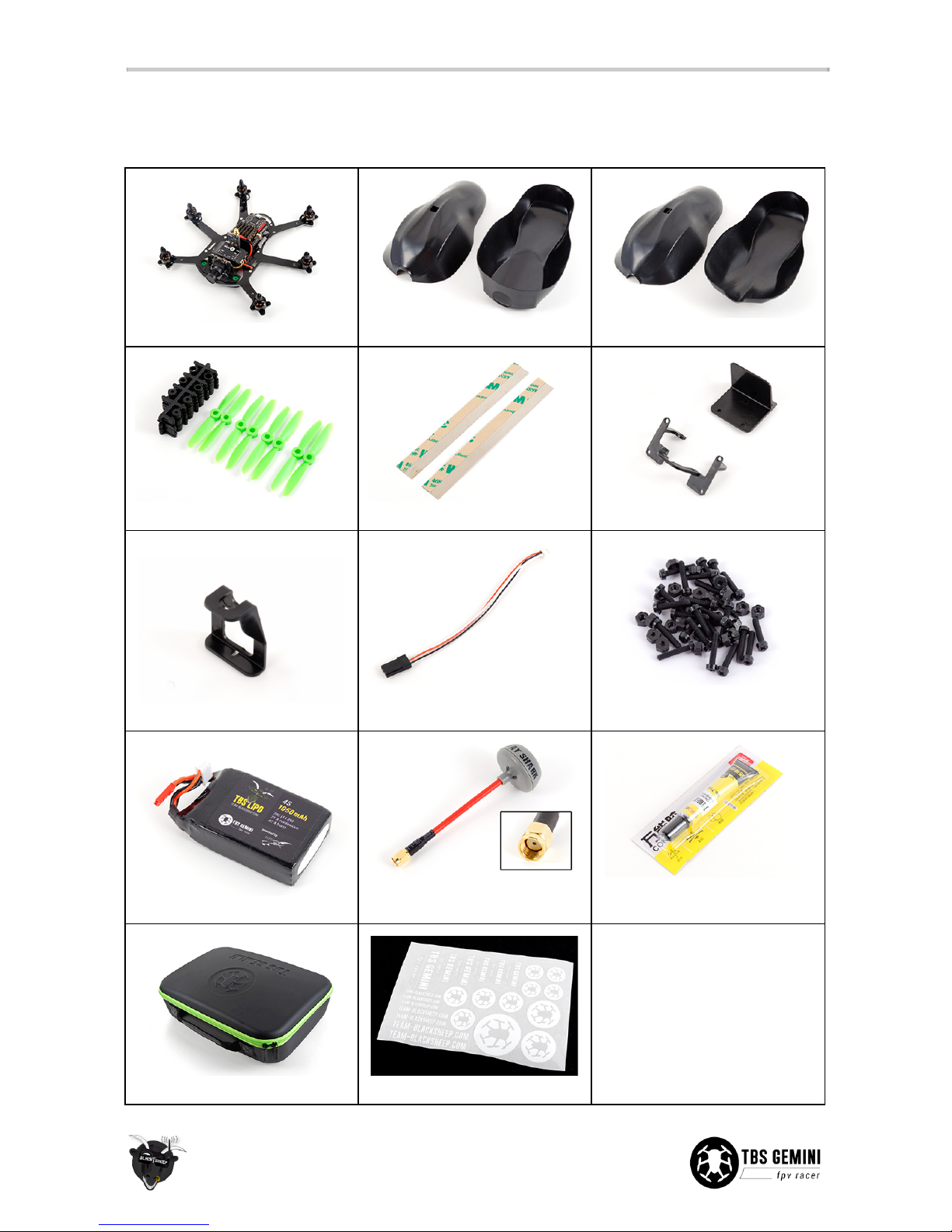
IN PACKAGE
The following is included in the base TBS GEMINI kit. Replacement parts are available online, if needed.
1x Assembled GEMINI frame
1x Set of film canopy - top/bott.
1x Set of racing canopy - top/bott.
8x 4x4.5-in propellers (CW, CCW)
2x Canopy metal strips
1x Set of racing carriage kit
1x VTX cable extension holder
1x PPM header cable for RX pwr
and PPM/S-BUS/D-BUS
1x Bag of light-weight M2 nylon
screws for motor mounts
1x TBS LiPo pack - 3S or 4S
1x SpiroNet Grey RHCP RP-SMA
antenna
1x Cement glue (“gooey”) to lock
parts and electronics for racing
1x GEMINI carrying case
1x Sheet of GEMINI stickers
-
5

Quick Start Guide - BNF set
The following steps will get you setup and ready to fly quickly. It is a condensed version intended for
experienced pilots. Each step is elaborated in more detail in this manual if you are new to this.
You will need to install a R/C receiver, configure the COLIBRI flight control, potentially adjust VTX frequency,
insert the battery and install the propellers.
This section requires the following equipment.
●Desktop or laptop computer for configuration (OS X/Win/Linux)
●5-ch R/C Radio transmitter and receiver with PPM/S-BUS/D-BUS
●5G8 FPV receiver system or FPV goggles
●Optional, Mobius HD camera (when using the film canopy)
Let’s go!
1. Connect the supplied PPM cable to the R/C receiver and the other end to the header on the I/O board
marked “PPM/CH1/UART2RX” - configure the receiver to output PPM/S-BUS/D-BUS
2. Depending on the R/C receiver, install it under the I/O board or over the CORE PNP25
3. Install the latest TauLabs GCS configuration software and connect a micro-USB cable to the COLIBRI
flight controller
4. (for S-BUS receivers only!) Open TauLabs GCS, open “Configuration”, go to the “Hardware” view,
change “RcvrPort” to “Disabled” and “UART2” to “S.BUS” - unplug all power to reboot
5. Turn on the radio, create a new model preset, attach the video transmitter antenna, connect a LiPo
battery to the frame, bind the receiver, open the “Input” view (in Taulabs GCS, under the
“Configurations” tab) and run through the “Configuration Wizard” to map the controls and switches,
go to “Arming Settings” and change it to “Yaw Right”, flip the flight mode switch to “Pos. 1 Leveling”
6. Now, cut the metal strips to 10 mm pieces and bend two of the ends to form a half-triangle, key the
location of the magnets on the side of the canopy and glue in place using superglue (see p15 for
details)
7. Cut away a small window on the video transmitter for the configuration switches and set it to one of
the supported frequencies for your video goggles
8. Mount the Mobius HD camera on the bottom of the frame using the velcro pad and rubber bands or
black tape, configure picture orientation to be upside-down
9. Insert the LiPo battery using the preinstalled elastic band, with the connectors facing forward
10. Prepare the propellers with the correct M4 adapter rings and install them with the text facing up,
rotating in the direction shown on the frame arms
11. Put on the canopy and antenna, connect the LiPo battery, start the Mobius recording and go fly!
6

R/C receiver
Install R/C receiver
A small or micro R/C receiver will fit underneath the I/O board, with the antennae feeding down the rear
arms. If the receiver is too big, mount it in the front section on top of the CORE PNP25 unit or under the
frame. Try to get as much separation between the R/C receiver- and VTX antenna as possible.
A short list of TBS recommended PPM/S-BUS/D-BUS receivers:
●FrSky D4R-II: Enable CPPM by shorting/jumping signal pin ch3 and ch4, now ch1 will output PPM,
ch2 will also output RSSI
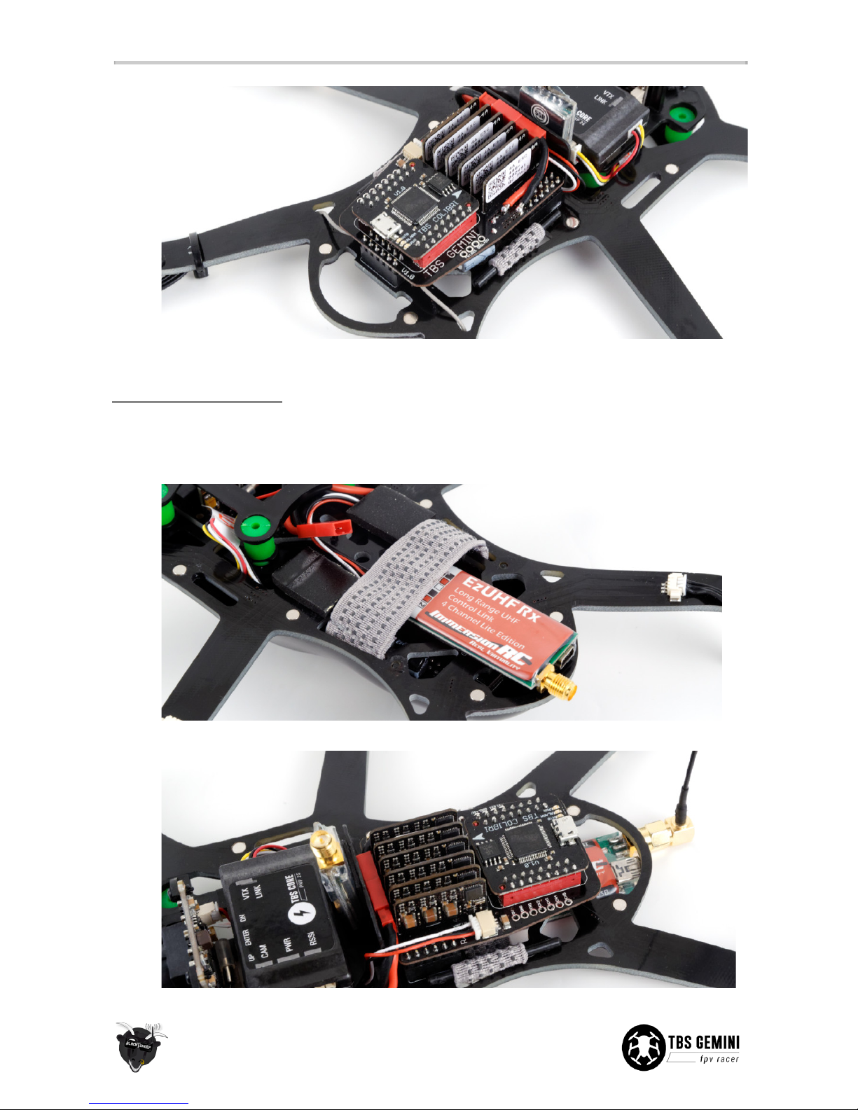
●EzUHF 4ch Lite: Use the ImmersionRC Tools to make ch1 output PPM, the unit barely fits under the
I/O board and might require extending the SMA connector 10-15 mm
●DJI Phantom 2, DJI DR16 Rx: To use a DJI receiver, simply connect the supplied cable on the D-BUS
header and configure TauLabs GCS to use S-BUS -
Note that Phantom Vision/FC40 uses 5G8 control
and are thus not compatible with 5G8 video systems. All other DJI systems are on 2G4
For all other receivers, inspect the manufacturers instructions to identify the supported protocols,
dimensions and layout of output header(s). Traditional PWM channels for all controls is possible but requires
some planning, see section later in the manual.
Power is provided by a 5V regulator on the frame. Use the supplied PPM cable to connect power to the R/C
receiver. If you consider using a Spektrum satellite receiver, see the installation section later in the manual.
7

Receiver under I/O board
Be careful to cover up any exposed metal if there is a chance of short-circuiting anything on the I/O board.
1. Disconnect the red JST battery connector to the I/O board
2. Gently wiggle the front and back of the board to remove it from the sockets, be sure not to bend the
pins
3. Place the receiver between the three header sockets on the GEMINI board with antennae facing the
rear
4. Reposition the I/O board over the headers and press firmly to ensure all the sides are properly
installed. It is important that all the headers fit tightly into the sockets - no bulging/pushing. Connect
the other end of the PPM cable to the I/O board.
8
5. Strip the antenna to the arms, cut a slot in the top canopy to avoid the cable from being sheared off
Receiver under the frame
If the receiver is long and has a slim profile (<8 mm), it will fit between the battery and the the frame.
1. Connect the PPM cable to the receiver and it it through to the top side
2. Add a piece of adhesive foam tape to the receiver and position it on the rear end of the frame
3. Align the antenna connector to the edge of the frame and connect the PPM cable to the I/O board
9

4. Add two foam pads and a foam sheet between the battery for protection and cushioning
5. Cut a notch in the bottom canopy for the antenna connector and antenna
An alternative way to install the EzUHF Lite, is to install it under the I/O board and modify the VTX plastic
support to let the PPM cable through. This lets the receiver sit tightly and with a SMA extension adapter will
put the antenna connector out on left-rear side.
Bind radio and receiver
Create a new model for the GEMINI if your radio supports presets. Pair your R/C radio and receiver as
instructed for your particular setup (FrSky, Futaba, Spektrum, DJI, EzUHF).
The following is a quick binding summary of the most popular radio system.
●FrSky Taranis: On radio, open Model Setup, select D8 (D4R-II) or D16 (X4R-SB) and enter Bind mode
- On the receiver hold the R/S button while applying power - rapid flashing indicates bind complete
●Futaba: Turn on the radio, when the RF signal LED is solid, press the “ID SET” button on the receiver
for two seconds - the LED on the receiver should turn solid when done
●Spektrum: Insert the binding plug on the receiver, on the radio hold the bind button on the back
while turning on the radio or use the bind menu - the receiver LED should stop flashing continuously
●DJI: Power the receiver, press the bind button, turn on the transmitter - the receiver LED should turn
off when complete
●EzUHF: Toggle the transmitter power switch to Low, hold the bind button while turning on the
transmitter, turn on the receiver and hold the bind button on the receiver for 5 seconds - the
transmitter should stop beeping
10

Configure COLIBRI flight control
Install drivers and software
Download the TauLabs configuration software and driver for the TBS COLIBRI flight controller, from
https://github.com/TauLabs/TauLabs/releases/ (OS X/Win/Linux), links at the end of the latest post.
Open the TauLabs GCS software and connect a micro-USB cable to the COLIBRI board. GCS will detect the
board and at the bottom of the view it should indicate that the controller is connected. Open “Configuration”
and in the “Hardware” view it should recognized the GEMINI frame.
The TBS tuned settings will automatically be loaded from the board and shown. Resetting back to TBS settings
is described later in the manual.
Setup inputs and outputs
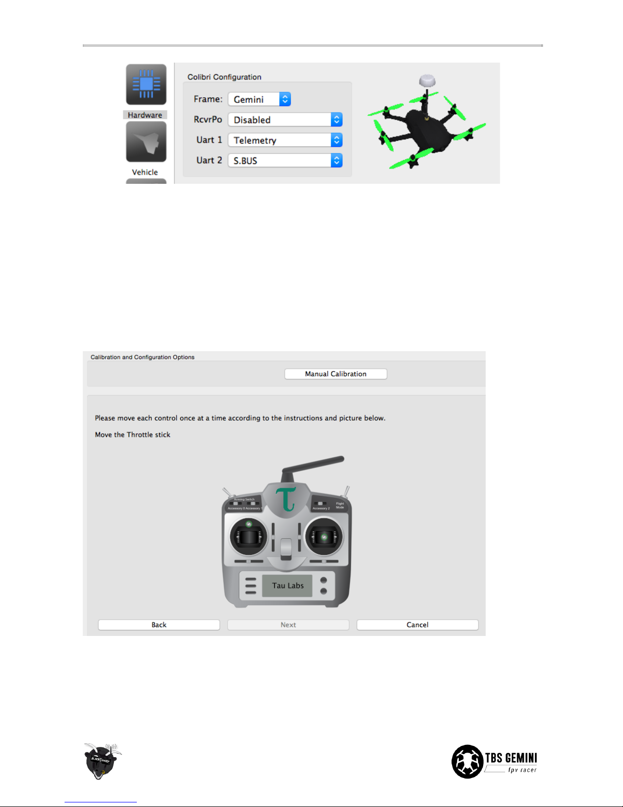
Open the “Hardware” view, and depending on the R/C receiver used, configure for PPM or S-BUS/D-BUS/DSM.
These are protocols to make sense of the received R/C signal.
Note that the CH1 and UART2 ports are joined on the same signal lane, meaning that “RcvrPort” and “UART2”
in GCS can NOT be both be enabled at the same time.
For PPM compatible receivers, under “RcvrPort” select “PPM, click “Save” and remove power to reboot the
controller with the new settings.
For S-BUS/D-BUS/DSM, set “RcvrPort” to “Disabled” and under “UART2” select “S.BUS” for S-BUS/D-BUS
(Futaba or DJI) or “DSM2” (DX7) / “DSMX (11bit)” (DX8, DX9) for Spektrum satellites - detailed later in the
manual.
11
Next, with a new model set up on the radio and the receiver bound to the transmitter, attach the video
transmitter antenna and connect a LiPo battery to the GEMINI to power the R/C receiver (USB will not provide
power to the receiver).
Open the “Input” view and click “Start Configuration Wizard” to initiate the stick-to-channel recognition
process. Also complete the failsafe stage. You can skip the last auxiliary accessory switch steps.
If the controls are not recognized, check that the receiver outputs the right signal and trace the signal wire to
ensure a proper connection.
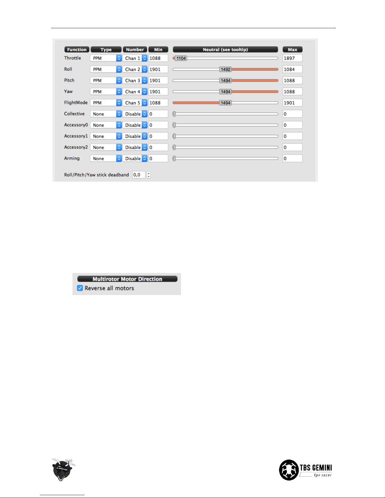
The final mapping will be shown in the main view, you can fine adjust and tweak settings if needed. Your
setup will differ from what is shown in the following image.
12
You should be able to see all the stick inputs “live” and the current position of the flight mode switch under
the “Flight Mode Switch Settings” tab.
Because of the way the flight controller is implemented, the motors are run in reverse. This requires the
mixer settings to have “reverse all motors” checked. The motors are reversed by default, so you do not need
to change anything. If your Gemini spins when taking off, however, you can fix the problem as follows:
1. Open the “Vehicle” view, navigate to the bottom section of “Mixer settings”
2. Make sure “Reverse all motors” is ticked, click “Save”
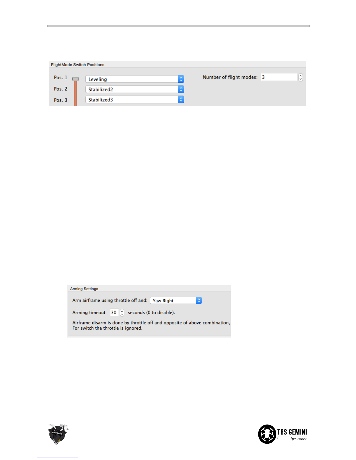
Flight modes
For auto-leveling and an easy first flight, make sure the toggle switch on your radio is set to “Pos. 1 -
Leveling”.
The default GEMINI flight modes are set up as follows.
●Postition 1 “Leveling” - Uses the gyroscopic sensor to self-level when you let go of the sticks. Move
the pitch or roll stick and the aircraft will tilt and hold the angle as long as you keep the stick pushed.
This mode is also known as “Attitude”.
●Postition 2 “Stabilized2” - Manual rate mode but with pitch and roll lock. This uses the gyro to help
maintain zero rotation. Push the sticks to change the angle of the aircraft, e.g. you have to do all the
work to fly true and level. Once you are confident in “Leveling”, switch to this mode.
●Postition 3 “Stabilized3” - Full manual rate mode with no help from the gyro, can be less locked in
than “Stablilized2”.
13
See https://github.com/TauLabs/TauLabs/wiki/Flightmode-Settings for further details how the different flight
modes behave.
Set failsafe
When the flight controller detects a failsafe (caused by equipment or range failure) it will turn off all the
motors (sets throttle to zero). This is the safest behavior compared to potentially having settings that cause it
to float off or even climb higher.
The failsafe setup is a two stage procedure.
1. Set up failsafe on the R/C receiver (per manufacturer instructions), normally by pressing a F/S button
to not output any pulses on the PPM/control cable, or more traditionally to preset the desired stick
position in a failsafe situation (e.g. low throttle) - the former option is highly preferred
2. Run the TauLabs GCS wizard to let the flight controller know what constitutes a receiver operating in
failsafe mode
Setting up arming
Caution: Always remove the propellers before setup or doing a reconfiguration!
The controller is by default set to disarm/disabled controls for safety after running the setup wizard.
1. Open “Input” and go the “Arming Settings” tab
2. Change “Always Disarmed” to “Yaw Right” (or your stick or switch preference)
To arm and fly, hold the throttle stick low and at the same time move the yaw stick to the right for two
seconds. The motors will automatically engage and start to spin if a battery is connected - this is to ensure
that the motors always keep spinning in flight even when the throttle stick is low (takes time to spin up the
props).
Raising the throttle stick will increase the power to the motors. Increase the throttle further and it will start to
hover. To disarm, lower the throttle to zero and move the stick to the left (opposite side of arming).
14

Install canopy brackets
The frame has six embedded magnets to lock the top and bottom canopy in place. The kit includes a two
metal strips which needs to be cut to length and installed with superglue (not the supplied cement glue).
The final bracket should resemble a half-triangle. The inner tab prevents scratches and wires from catching.
1. Start with the bottom canopy and position it over the frame, make key markings with a pencil on the
side of the canopy where there are magnets located
2. Use a cutting plier or scissor to cut length of 10 mm, total 24 pieces (for four canopy halfs)
3. Make two bends, the first approx. 3 mm in from the end without adhesive and another approx. 6 mm
from the other end. Use a small plier to hold the piece to get a sharp bend.
15

4. Add a drop of superglue to one bracket at a time. Align it with the key markings and adjust so it is
flush to the trim of the canopy. If the bracket stands out, bend it some more to minimize canopy
gaps.
5. Perform this for all the metal brackets and repeat for the top canopy and the second set.
16

Set-up video transmitter
The included TBS UNIFY 5G8 200mW video transmitter and encased cloverleaf antenna provides great range
(up to 1km line-of-sight) and supports 32-channels (compatibility with Fatshark, IRC, DJI and all other brands).
The 5G8 frequency band means no interference when using a 2G4 R/C transmitter.
The kit comes with a VTX extension cable holder if you want to replace and use a larger VTX which does not fit
the standard VTX spot.
See the official manual to find the frequency switch combination for your FPV receiver/goggles,
www.team-blacksheep.com/tbs-unify5g8-manual.pdf. Make sure no-one else is using the same frequency in
your proximity before turning on your transmitter.
1. Cut a small window in the heat-shrink around the DIP switch using a precision knife
2. Flip the right switches (up is toward “ON”) and attach the antenna
3. Connect the LiPo battery to test the frequency and video feed (remember to remove the lens cap!)
Important: Keep the antenna mounted at all times while the VTX is powered on, otherwise the unit could
heat up and burn out over time. Forgetting it for a few minutes is normally not a problem.
Note that the TBS UNIFY uses RP-SMA (reverse polarity) connectors, this means that the female connector
body (outside threads) has a center pin not an inner receptacle. It makes no difference on the receiving
end/googles, just the connection is reversed. If you replace the antenna, the connector has to be of the same
type.
17
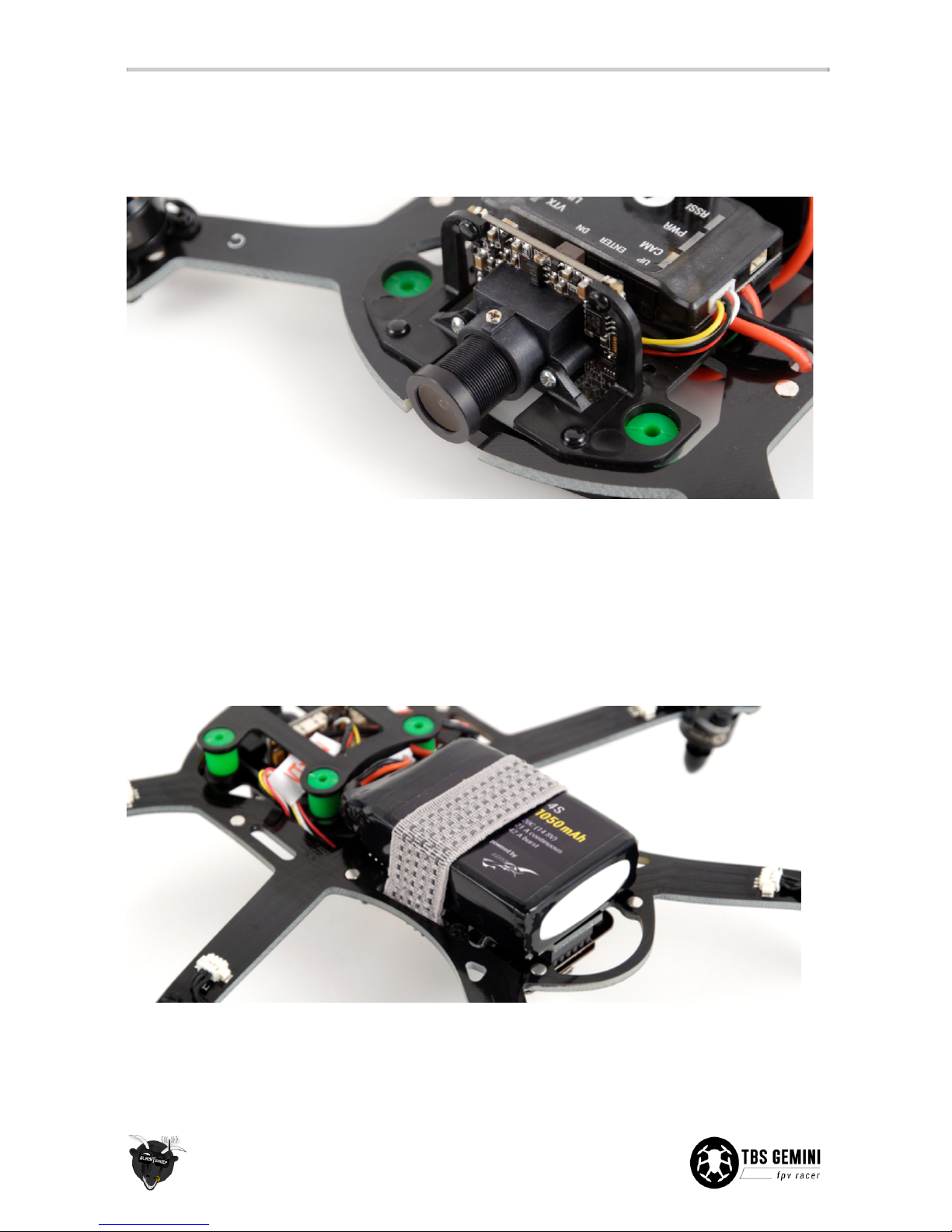
Pilot camera
The TBS CHIPHIP V2 600 TVL PAL pilot camera comes with a 2.8 mm lens and pre-configured to capture a
bright and crisp image. No configuration required.
If the image turns out to be out of focus, loosen the phillips set/grub screw on the top and turn the lens. The
lens is also exchangeable to get a narrower or wider viewing angle, e.g. 3.6 mm (90°) or 2.1 mm (150°) focal
length. The stock 2.8 mm lens provides a 115° view, which is a good all-around angle of view.
Mount battery
The frame comes with a durable elastic band on the bottom side. This keeps the LiPo battery tightly mounted.
Insert the battery with the connectors facing forward.
To power the GEMINI, connect the battery lead with the corresponding connector from the CORE PNP25
which sticks out through the frame slots. The GEMINI carrying case can hold up to six to eight batteries plus
one strapped to the frame.
18

Mount Mobius HD camera - film canopy
The stock setup comes prepared with a carriage for a Mobius HD camera (available separately), but it can be
swapped out for a much lighter carriage to only hold the pilot camera. Coupling this with the streamlined
racing canopy, makes for a serious rocket, especially on 4S! See section later in the manual for conversion
specifics.
Configuration of the Mobius is necessary to get the picture orientation right. Download the manual and
software from https://www.mobius-actioncam.com/softwareuser-guide/
1. Apply the supplied adhesive velcro pad over the center of the Mobius carriage
2. Position the Mobius camera a bit off center and straight with the body aligned to the frame edge
3. Use the bottom film canopy to help line up the camera lens all the way forward. Secure it with a few
rounds of rubber bands or black tape.
19

4. When properly positioned, the footage should not show the propellers in view (neither normal or
wide-angle B lens). If you do see the propellers, ensure that the camera is fully straight and move it
towards the front by a bit.
Since the camera now is mounted upside-down to allow access to the control buttons, enable 180° picture
rotation in the Mobius configuration to get easy-to-manage footage. Keeping a separate SD card for the
GEMINI makes it easy to swap picture orientation in the field between platforms.
20
Table of contents


