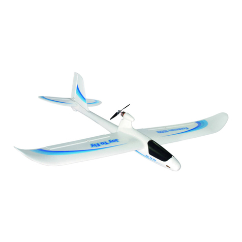
Joysway Dragonfly 6302 User manual

ATL Sport Model
All Terrain Launching R/C Brushless Airplane
●Wing span: 700mm
●Wing loading: 25g/dm2
●Fuselage length: 970mm
●Flying weight: 575g
●Motor thrust power: 850g
SPECIFICATION:
Model No:6302
IMPORTANT NOTE:
J4C03 2.4GHz 4CH transmitter is supplied with MODE 2 as
standard set, If needed, you could simply switch to MODE 1
by easy steps, see details in page 9.
V2013-7 manual

Model No:6302
WARNINGS
IMPORTANT: Before beginning assembly, please read and understand the warnings listed following. Failure to read and
understand these warnings could lead to bodily harm and/or injury.
1. This model is not a toy. It is for beginner, intermediate and experienced modeller
2. Assemble the plane according to the instructions. Do not alter or modify the model. If you make any modifications, you will
void your warranty.
3. It is highly recommanded to fly this model under the guide of experienced modeller
4. Test the operation of the model before each flight to insure that all equipment is operating properly, and that the model
remains structurally sound.
5. Fly in large open areas free of trees, people, buildings or any other obstacles.
6. Always be conscious of the spinning propeller. Be careful not to allow loose clothing to be drawn into the propeller.
7. Always turn on the transmitter before turning on the airplane and always turn off the airplane before turning off the transmitter.
8. Always unplug the flight battery when not flying the airplane.
9. Do not attempt to catch the airplane while flying.
10. It is important to make sure you are always using fresh or fully charged batteries. Never allow the batteries to run low or
you could lose control of the airplane.
FCC REQUIREMENT
This device complies with Part 15 of the FCC Rules. Operation is subject to the following two
conditions: (1) This device may not cause harmful interference, and (2) This device must accept
any interference received, including interference that may cause undesired operation.
CAUTION: Changes or modifi cations to this product not expressly approved by the party responsible forcompliance
may void the user’s authority to operate the equipment.
Dragonfly All Terrain Launching Airplane PNP
page 2

KIT CONTENTS
Fuselage Left wing Right wing Right horizontal tail
Left horizontal tail
6*4*400mm carbon fiber tube
6*4*200mm carbon fiber tube
3*1.4*120mm carbon fiber tube
Push rod for horizontal tail Cohere sticker for horizontal tail
Battery velcro
1.5mm Allen key
Spare 6*4 propeller
Battery compartment hatch
Electronic compartment hatch Y wire cord
Ballon 11.1V 1200mAh LiPo
(Optional Part) 2.4GHz 4CH Transmitter and Receiver
(Optional Part)
ITEMS REQUIRED FOR COMPLETION
2.4GHz 4CH Transmitter and Receiver.
11.1V 1200mAh 20C LiPo pack. (Battery capacity can be from 1200mAh to 2200mAh)
2S/3S Balance charger with adapter.
page 3

3. Insert servo extend wire into the fuselage hole. plug in left wing with fuselage and press them together so that doulbe side
tape could secure them.
4. Insert 6*3*200mm carbon fiber tube from right side of fuselage through wing as photo show.
Fllow the above way to insert 6*3*400mm carbon fiber tube on fuselage through wing.
1. Remove battery compartment hatch and electronic compartment hatch as photos show.
2. Rip off the double side tape on the left wing as photos show.
ASSEMBLING YOUR DRAGONFLY
page 4
1
1
2
3
3
4
6*3*200mm
6*3*400mm
4

5. Rip off right wing doulbe side tape, align carbon fiber tube with two holes on right wing side and
press right wing to join fuselage. before they join together, make sure the servo extend wire get through
the hole on fuselage. the servo extend wire can’t be stuck when right wing join with fuselage.
6. plug in the two servo extend wire on wings with Y wire cord which has Aileron marking label.
Noticing the servo wire correct polarity.
7. Insert left horizontal tail into left side of fuselage as show.
8. Insert 3*1.4*120mm carbon fiber tube from right side fuselage through left horizontal tail as show.
9. Align two carbon fiber tubes with two holes on right horizontal tail and install right horizontal tail.
page 5
5
5
6
6
7
8
9

PREPARATION BEFORE FLIGHT
STEP 1: INSTALLING THE TRANSMITTER BATTERIES
1. Carefully remove the battery cover from the back of the transmitter by pulling down on it with one hand while holding the
transmitter with your other hand.
2. Install 4 fresh AA Alkaline batteries, being careful to make sure that the polarity is correct for each battery.
3. After double-checking that the batteries are installed correctly, reinstall the battery cover, making sure it’s firmly seated
into place.
8. Use two pcs of cohere sticker to join two horizontal tails together up and down.
9. Insert Z shape end of pushrod into the outer hole of servo arm as show. The other end of pushrod get through
the clevis and secure it with 1.5mm allen key as show. make sure horizontal tail are in neutral position.
Servo wires connecting to Receiver (Apply to MODE 1 and MODE 2)
1. Plug in Aileron servo wire with Channel 1.
2. Plug in Elevator servo wire with Channel 2.
3. Plug in Throttle wire with Channel 3.
4. Plug in Rudder servo wire with Channel 4.
5. Wrap receiver with supplied ballon and place it well inside the electronic compartment. then reinstall the hatch.
page 6
8
8
8
9
9
9

1
2. Put LiPo pack inside the fuselage, using hook and loop strap to secure them tightly on position.
3. Attach the battery connector to the matching connector of ESC. And reinstall the hatch of fuselage, making sure it is
secured tightly.
4. The proper CG position should be 10mm away from the cutting edge of bottom fuselage, please refer to the picture. If not,
please adjust the position of battery.
STEP 2: CHARGING THE LIPO PACK (NOT INCLUDED)
CAUTION:
1.Only use a LiPo approved charger. Never use a NiCd/NiMH peak charger!
2.Never leave the battery unattended during the charging process. Always keep this charger out of reach of children.
3.Stop charging immediately if any abnormality occurs, such as power indicator is off, the temperature of the battery raise
rapidly.
4.Do not attempt to disassemble the charger
5.Do not set the charger on carpet during the charging process.
6.Un-plug the charger DC Adapter from the vehicles’s cigarette lighter if you do not inend to use it for a period of time.
The following parts are optional purchasing parts.
11.1V 1200mAh 20C LiPo pack.
2S/3S Balance charger with adapter
NOTE: Familiarize yourself with the charging procedure of the lipo battery. Read the charger Manual completely and fully
charge the lipo battery.
STEP 3: INSTALLING THE LIPO PACK
IMPORTANT Always turn on the transmitter before turning on the airplane and always turn off the airplane before turning off
the transmitter.
1. Push down the throttle stick (Left Stick, MODE 2) till the end as shown. Switch off “MXMD” button on top position,
because Dragonfly don’t need mix control function on wing or tail. Then turn on the transmitter by pressing on the power
switch.
page 7
2
3
CG line
10mm
4
1

page 8
Elevator down
Elevator up
Aileron
Ieft right
Aileron
Throttle Trim Elevator Trim
Aileron Trim
Power indicator
Power switch
Reverse switch on aileron Reverse switch on throttle
Reverse switch on elevator
Charge Jack
Mode 2
STEP 4: FAMILIAR WITH RADIO CONTROL SYSTEM
Throttle Max
Throttle Min
Rudder
Ieft right
Rudder
Elevator Trim Throttle Trim
Aileron Trim
Rudder Trim
Power indicator
Power switch
Reverse switch on aileron
Reverse switch on throttle
Reverse switch on rudder
Reverse switch on elevator
Charge Jack
Mode 1
Aileron
Ieft right
Aileron
Throttle Max
Throttle Min
Rudder
Ieft right
Rudder
Elevator down
Elevator up
Rudder Trim
Mix Control Switch
Mix control Switch
NOTE:
1. MXMD button is mix control ON/OFF button, switch down as “ON” if model is with mix control function.Otherwise switch
up as “OFF”.
2. Supplied plastic screwdriver on transmitter handle, use this part to adjust Aileron, Elevator, Rudder dual rate.
Aileron dual rate
Elevator dual rate
Rudder dual rate
Aileron dual rate
Elevator dual rate
Rudder dual rate

5
4
1
2
3
page 9
CHARGING(FOR RECHARGEABLE BATTERIES)
The J4C03 transmitter has a charge jack that allows rechargeable AA cells (not included) to be charged in it, using a suitable
battery charger.(Output: 6V, Max500mA)
Caution: Never try to charge dry cell batteries in the transmitter. They will leak and could explode!
Caution: Never leave the radio/charger unattended when charging.
Caution: To prevent the possibility of accident, overheating and/or short circuit, always disconnect your battery charger from
its power supply when not in use.
Note: When rechargeable batteries are finally depleted (dead) they should be taken to a designated
recycling centre for disposal. DO NOT dispose of them in household waste.
J4C03 2.4GHz 4CH transmitter is supplied with MODE 2 as standard set, If needed, you could simply switch to MODE 1 by
easy steps as belowing:
TRANSMITTER MODE SWITCHING
Step 4: Screw off down-right screw completely until the screw head is almost even with back panel.
Step 5: Screw off up-right screw, but not completely. adjust this screw tightness so as to adjust the Elevator stick(left stick)
spring tightness as you wanted.
NOTE: If switch back form MODE 1 to MODE 2, firstly switch MODE button to MODE 2 under battery cover, screw off the left
two screws, Screw down the right two screws, adjust down-left and up-right screws tightness so as to adjust the
Throttle stick and Elevator stick spring tightness as you wanted.
Step 1: Open battery cover, switch MODE button to MODE 1.
Step 2: Use screwdriver to screw down the up-left screw tightly as photo shown.
Step 3: Screw down the down-left screw as photo shown, but not fully tighten, adjust this screw tightness so as to adjust the
throttle stick (right stick) spring tightness as you wanted.

STEP 5: TEST THE THROTTLE (Mode 2)
1. Move the throttle control stick forward slowly, the motor
rotates faster gradually.
WARNING: Keep everything clear of the propeller once the
battery is plugged in. Do not try to stop the propeller by hand
or anything else.
3. Let Aileron control stick returns to its neutral position, the aileron returns to its neutral position.
2. Move the aileron control stick to the right, the left aileron moves down and the right aileron moves up.
1. Move the aileron control stick to the left, the left aileron moves up and the right aileron moves down.
NOTE: If the motor doesn’t react with the throttle increasing,
please check the power supply or the battery capacity and
the throttle reverse switch and make necessary adjustment.
NOTE: If the movement of aileron works in opposite position, please check the aileron reverse switch and make necessary
adjustment.
STEP 6: TEST THE AILERON (Mode 2)
NOTE: If aileron doesn’t return to neutral position, then adjust the aileron trim button to make it in neutral position.
page 10
TRANSMITTER/RECEIVER BINDING
The binding process effectively ties the J4C03 transmitter and J5C01R receiver together. Under normal circumstances, both
items are supplied like this from the factory. If, however, you find that your transmitter and receiver are not bound (receiver’s
red LED will be lighting), you should do the following:
1. Push down the throttle stick (Left Stick, MODE 2) till the end as shown. Switch “ON” the transmitter.
2. Connect LiPo pack to ESC’s matching connector
3. Press down the “BIND” button on the receiver as shown, until the receiver’s red LED flash then let go, the receiver’s green LED
will be lighting to indicate that binding has been successful and the receiver will now accept commands from the transmitter.
Note 1: You would also need to carry out the binding process if you were to replace the included receiver with another one.
Note 2: Typically, for the binding process to be effective, transmitter and receiver should be no more than one meter apart and
no other similar devices should be within 10 meters of both during setup.
10°
1
10°
2
3
REMARK: You could adjust the aileron servo traveling value by using the plastic screwdriver to adjust the aileron
dual rate on transmitter.
1
3
2

STEP 7: TEST THE RUDDER (Mode 2)
STEP 8: TEST THE ELEVATOR (Mode 2)
3. Let rudder control stick returns to its neutral position, the rudder returns to its neutral position.
NOTE: If rudder doesn’t return to neutral position, then adjust the rudder trim button to make it in neutral position
1. Move the rudder control stick to the left, the rudder turns to the left.
2. Move the rudder control stick to the right, the rudder turns to the right.
NOTE: If the movement of rudder works in opposite position, please check the rudder reverse switch and make necessary
adjustment.
NOTE: If elevator doesn’t return to neutral position, then adjust the elevator trim button to make it in neutral position.
3. Let elevator control stick returns to its neutral position, the elevator returns to its neutral position.
NOTE: If the movement of elevator works in opposite position, please check the elevator reverse switch and make necessary
adjustment.
2. Move the elevator control stick forward, the elevator will be down.
1. Move the elevator control stick backward , the elevator will be up
page 11
REMARK: You could adjust the elevator servo traveling value by using the plastic screwdriver to adjust the elevator
dual rate on transmitter.
REMARK: You could adjust the rudder servo traveling value by using the plastic screwdriver to adjust the rudder
dual rate on transmitter.
30°
1
30°
2
3
15°
1
15°
2
3

page 12
FLIGHT MANUAL
VALUABLE EXPERIENCE
Choose a good flying site and day
1. The ideal location for flying has wide-open space in four directions with no people
2. Choose location carefully! Do not operate model near these areas: Houses or buildings, children’s play areas, road
traffic, railways, airports, overhead powerlines.
3. Fly in calm weather conditions with no winds or gentle winds.
1. Check the propeller and all screws are securely fastened.
2. Check airplane responds properly to control signals.
3. Test the range of the radio signal. It is recommanded that have around 100 M range check.
Pre-flight check
WARNING: If you lose control of your airplane , never wade into deep water or water with strong currents to retrieve it.
First, hold the transmitter as high as you can to try to re-establish control. If this does not work, find another way to
move closer to the model, but do not endanger yourself in the process!
Take Off
1. Place airplane on water gently,apply half throttle,adjust rudder stick to control airplane sliding on water
and facing the wind.
2. Apply full throttle and adjust rudder stick to control airplane sliding in high speed on water straightly facing the wind.
3. When airplane is sliding in high speed straightly, apply adequate amount of elevator, airplane head will raise and
going to take off
NOTE: When airplane take off, immediately reduce elevator control value to control airplane ascend slowly.
Landing
After Landing
Disconnect the battery, then, switch the transmitter off. Remove the battery from the fuselage, Check the airplane over
to make sure nothing has come loose or may be damaged.
1. For your first couple of flights we recommend that you attempt to land with reserve battery power.
2. During your first flight, while at a high altitude, turn the motor off and notice how the Dragonfly seaplane reacts.
This will give you an idea of how the airplane will react during a landing. At this higher atltitude, familiarize yourself
with how the model responds at low power and slower speeds as this is how the model will fly when landing.
3. To land the Dragonfly seaplane, fly down wind, past the landing area. Gently turn into the wind and reduce the
throttle so that the airplane starts to come down. Adjust the throttle as needed to reach the landing area, but not
fly past it. Always land into the wind.
4. Just before landing on water, at about 0.5 meter above the water, apply a little up elevator, This will cause the
airplane to slow and settle on the water.
Steering
1. Aileron control to steer left, move aileron stick to left, combine with a small amount of up elevator(Elevator stick
down),airplane will steer left without losing altitude
2. Aileron control to steer right, move aileron stick to right, combine with a small amount of up elevator(Elevator stick
down), airplane will steer right without losing altitude.
3. Rudder control to steer left, move rudder stick to left, combine with a small amount of up elevator(Elevator stick
down),airplane will steer left without losing altitude
4. Rudder control to steer right, move rudder stick to right, combine with a small amount of up elevator(Elevator stick
down),airplane will steer right without losing altitude

page 13
Command And Fly (Mode 2)
Speed up
Speed down
Ascending
Descending
Nose turn right
Nose turn left
Left stick up
Left stick down
Right stick down
Right stick up
Left stick right
Left stick left
The Body incline
to Right
The Body incline
to Left
Right Stick Right
Right Stick Left

page 14
SPARE PART LIST
To order Dragonfly seaplane spare parts, use the part numbers in the spare parts list that follows.
PART NO. DESCRIPTION
Rudder Trim
Elevator Trim
Aileron Trim
Adjusting trims during flight (Mode 2)
3. Let go of control sticks. If airplane inclines to the left, adjust aileron trim to the right.
4. Adjust rudder, elevator and aileron trims so airplane flies straight and horizontal when sticks are free.
1. Let go of control sticks. If airplane moves left, adjust rudder trim to the right.
2. Let go of control sticks. If airplane moves upward, adjust elevator trim to downward.
630201 Brushless motor and motor mount
630202 11.1V 1200mAh 25C LiPO Pack
630203 40A brushless ESC
630204 Elevator/Rudder servo(PK2)
630205 Aileron servo (PK2)
630206 Main EPO Hatch without magnet
630207 elevator tail set
630208 motor and servo hatch cover
630209 left wing set
630210 right wing set
630211 pushrod for aileron (PK2)
630212 Wing attachement tube (PK2)
630213 Clevis (PK2)
630214 pushrod for elevator (PK2)
630215 pushrod for rudder (PK2)
630216 Fuselage set
630217 Velco strap for battery(PK2)
630218 Propeller and spinner set (PK2)
630219 Magnet set for hatch(PK2)
630220 Receiver EPO hatch
630221 Decal stickers set for fuselage and wing
610206 Control Horn set(PK6)
610307 3S balance charger with DC adapter

page 15

page 16
Table of contents
Other Joysway Toy manuals

Joysway
Joysway Mad Shark B-JS-8203 User manual

Joysway
Joysway super mono x v2 User manual

Joysway
Joysway 8807 User manual

Joysway
Joysway MAGIC VEE V5 User manual

Joysway
Joysway Mad Shark RTR MiNi EP F1 User manual

Joysway
Joysway Dragon Force 8805 User manual

Joysway
Joysway WARRIOR B-JS-9301BR User manual

Joysway
Joysway Invincible Razor ARTR 9501S Installation and operating instructions

Joysway
Joysway 9321 Offshore Infinity Deep Vee Installation and operating instructions

Joysway
Joysway SPRITE 750 Installation and operating instructions