TCE HT MOD B User manual

TCE HT MOD B
HARDNESS TESTER

2CHANGES AND TYPING ERRORS RESERVED CHANGES AND TYPING ERRORS RESERVED
Table of conTenTs
1. Overview 3
1.1 Indenter 3
2. Specifications 3
3. Application 3
4. Use 4
5. Verification and calibration 4
5.1 Verification without material 4
5.2 Verification with test block 4
5.3 Calibration of the dial 4
5.4 Calibration of the load spring 4
5.5 Replacing the indenter 5
6. Maintenance 5
7. Factors that will influence the accuracy of the tester 5
7.1 Material 5
7.2 Distance to the edge of the material 5
7.3 Distance between two measuring points 5
7.4 Oxidation 5
7.5 Coating 5
7.6 (In)correct use 5
8. Conversion table and charts 6

3
CHANGES AND TYPING ERRORS RESERVED CHANGES AND TYPING ERRORS RESERVED
Hardness tester tCe Ht MOd B
1. overview
Figure 1
No. Description No. Description
1Frame 7Adjusting nut
2Pivot screw 8Indenter cylinder
3Handle 9Load spring
4Reset key 10 Indenter
5Adjusting screw 11 Anvil
6Dial head 12 Return spring
1.1 indenTer
Figure 2
2. specificaTions
• Testing range: 0-20 HW
• Accuracy: 0.5 HW
• Weight: 0.5 kg
3. applicaTion
The TCE HT Mod B is used for measuring the hardness of aluminium and aluminium alloys within the range of
25-110 HRE/58-131 HV. The thickness of the material to be measured can be between 0.4 - 8 mm and with an
inner diameter of > 6 mm.

4CHANGES AND TYPING ERRORS RESERVED CHANGES AND TYPING ERRORS RESERVED
4. Use
See figure 1
Put the material between the anvil and the indenter and press down the handle until you can press it no further.
The dial head now indicates the hardness of the material. Make sure you grip and hold the handle tight while
reading the result.
5. verificaTion and calibraTion
5.1 verificaTion wiThoUT maTerial
• Press down the handle whilst there is no material between the indenter and the anvil.
• The dial should indicate 20 HW (+/- 0.5 HW). When this is not the case you must calibrate the hardness tester as
described in paragraph 5.3.
5.2 verificaTion wiTh TesT block
• Place the test block between the indenter and the anvil and press down the handle firmly.
• The dial should indicate the value indicated on the test block (+/- 0.5 HW). When this is not the case you must
calibrate the hardness tester as described in paragraph 5.4.
5.3 calibraTion of The dial
Figure 3
• Press down the indenter firmly with the handle whilst there is no material between the indenter and the anvil.
• Turn the adjusting screw with the screw driver to the left or the right until the pointer indicates 20 HW.
When the dial cannot be calibrated any more you must replace the indenter. See paragraph 5.5.
5.4 calibraTion of The load spring
See figure 1
• Undo the pivot screw and take out the bottom handle.
• Take out the dial head, but leave the cylinder in the frame. You can now see the adjusting nut.
Figure 4
• Turn the adjusting nut counter clockwise with the wrench when the deviation is < 20 HW, turn it clockwise
when the deviation is > 20 HW.
• By turning the adjusting nut a quarter of a full rotation the pointer on the dial will move 2-3 units either way.
• Put back the dial head, handle and pivot screw and check the hardness tester as described in paragraph 5.2.
Adjusting screw

5
CHANGES AND TYPING ERRORS RESERVED CHANGES AND TYPING ERRORS RESERVED
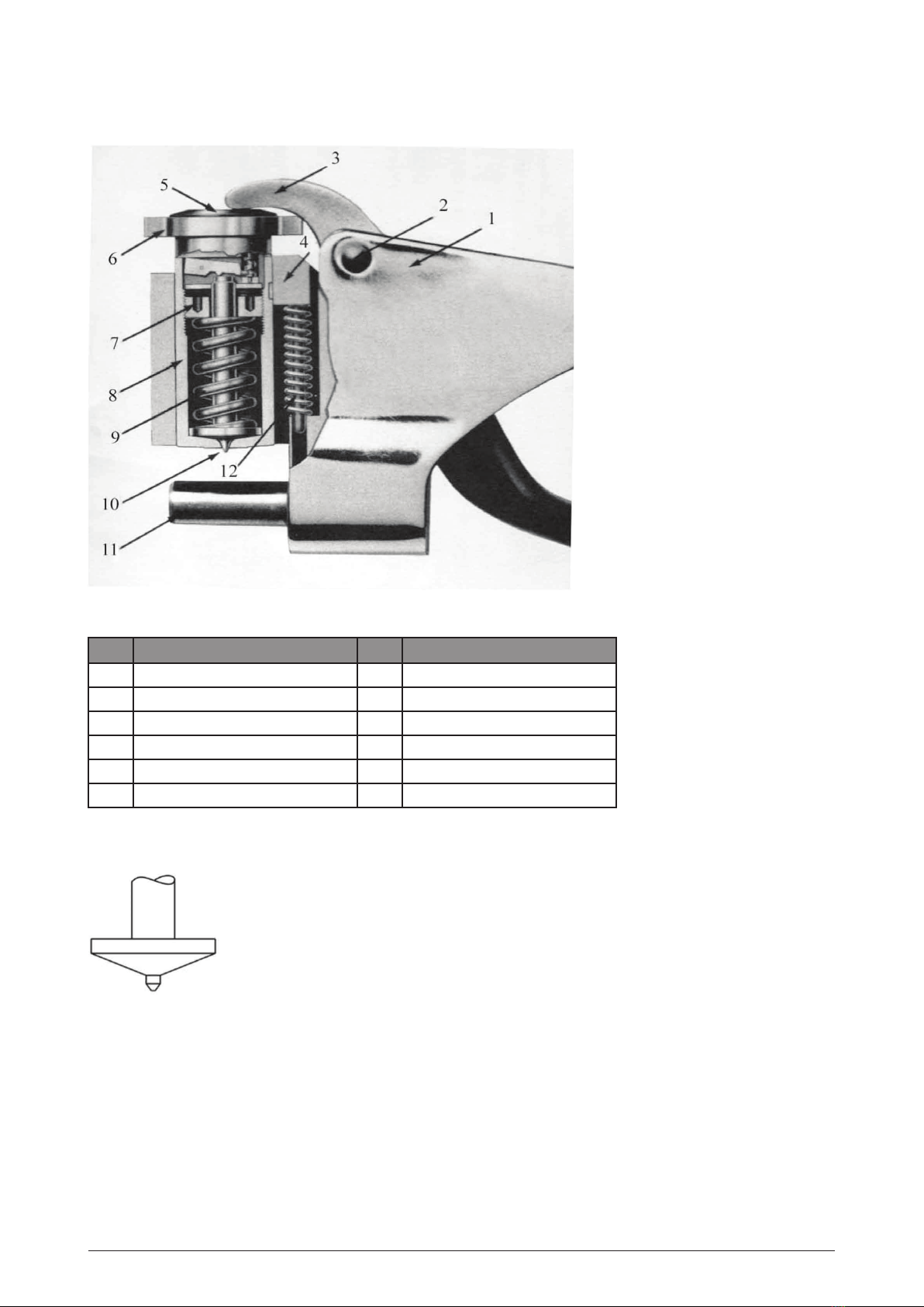
5.5 replacing The indenTer
When the hardness tester cannot be calibrated correctly anymore, the indenter is worn and must be replaced.
• Undo the pivot screw and take out the bottom handle.
• Take out the dial head but leave the cylinder in the frame. You can now see the adjusting nut.
• Loosen the adjusting nut (see also figure 4) and take out the indenter.
• Insert the new indenter and fasten the adjusting nut. Do not fasten the nut too tight as this will damage the
indenter.
• Calibrate the hardness tester as described in paragraphs 5.3 and 5.4.
6. mainTenance
This hardness tester is a precision instrument. Its service life depends on correct use and good maintenance.
• Clean the hardness tester every time you have used it with a soft cloth.
• The various parts of the tester have been treated to protect them against rust. However, always check the tester
for rust when you use it often or when you are using it in a damp environment.
• Never drop the hardness tester. This will influence the correct working of the tester and may even render it
useless.
• Do not remove any parts of the tester other than for calibration purposes. Removing further parts voids the
guarantee.
7. facTors ThaT will inflUence The accUracy of The TesTer
7.1 maTerial
The surface of the material to be measured needs to be free of dust and grains to ensure the accuracy of the
measurement.
7.2 disTance To The edge of The maTerial
The distance between the tip of the indenter and the edge of the material has to be at least 5 mm. When you
measure closer to the edge this may influence the result.
7.3 disTance beTween Two measUring poinTs
The distance between two measuring points has to be at least 6 mm. When you measure too close to an earlier
measuring point this may influence the result.
7.4 oxidaTion
Even though a layer of oxidation is thin, it will influence the result of a measurement. A layer of 10 µm will result
in a deviation of 0.5 to 1 HW (over).
7.5 coaTing
A coating on the material will give you a unreliable result. Therefore you should always remove any coatings with
sanding paper or a solvent.
7.6 (in)correcT Use
• You should check the accuracy of the hardness tester regularly and calibrate it if necessary (see chapter 5).
• Always place the material horizontally between the tip of the indenter and the anvil. Make sure the material
presses well against the anvil.
• Press down the handle firmly in one go. When you add pressure slowly this will result in an inaccurate reading.
• Make sure the material does not shift while measuring.

6CHANGES AND TYPING ERRORS RESERVED CHANGES AND TYPING ERRORS RESERVED
8. conversion Table and charTs
Table 1
Figure 5
Figure 6

7
CHANGES AND TYPING ERRORS RESERVED CHANGES AND TYPING ERRORS RESERVED
Our products are frequently updated and improved. Minor changes may not yet be incorporated in this manual.
Manufacturer and importer assume no responsibility for defects which result from not reading the manual
carefully or wrong use of the machine. No rights can be derived from this manual.
All rights reserved. No part of this manual may be reproduced in any form, by print, photoprint, microfilm or any
other means without written permission from the publisher.
© TCE Tools BV, Kennedylaan 14, Veghel, the Netherlands. Internet: www.tce-tools.nl

2016 V1
Table of contents