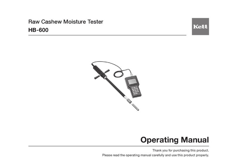
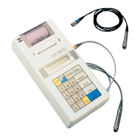
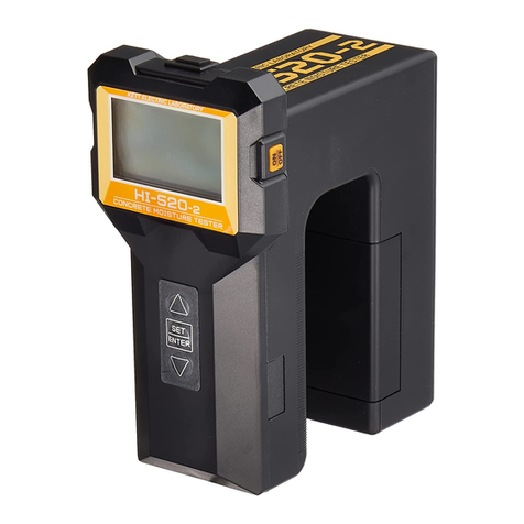
Kett LZ-990 User manual

Dual Type Coating Thickness Tester
LZ-990
Operating Manual
Thank you for purchasing this product.
Please read the operating manual carefully and use this product properly.

Safety Precautions
The Coating Thickness Tester may cause damage to objects being handled if the precautions
are not adhered to for safety purposes. The utmost care has been given to the safety of the
product, however take care to read the precautions in this operating manual for proper handling.
• Be sure to carefully follow all safety precautions.
Carefully read the operating manual.
• Do not use the unit if it is not functioning properly.
Immediately contact our service representative if the unit malfunctions or does not
operate properly.
• Measuring or Warning Indications.
The symbols indicated below are used in the operating manual and on the unit itself in
order to prevent accidents due to misuse of the product.
These symbols have the following meanings.
This symbol indicates something that must be strictly observed in
order to ensure the safe handling of the product.
Caution

Contents
1. Measuring Principles and Features.................................... 4
2. Specications ..................................................................... 6
3. Instrument View.................................................................. 7
4. Display Pattern ................................................................... 9
5. Keypad Functions............................................................... 10
6. Battery Installation.............................................................. 11
7. Operation............................................................................ 12
8. Settings............................................................................... 14
9. Calibration .......................................................................... 32
(1)Simplied ....................................................................... 34
(2) Multipoint....................................................................... 37
10. Battery Replacement.......................................................... 41
11. Notes for Measuring and Handling..................................... 42

4
• Electromagnetic method
(measurement of non-magnetic coatings on
magnetic metals)
If an AC electromagnet is brought into the proximity
ofiron(magneticmetal),thelevelofthemagneticux
flow through the coil changes resulting in changes
in the voltage on each end of the coil. This change
in voltage is detected by the current value and is
calculated in terms of coating thickness.
• Eddy Current method
(measurement of insulating coating on non-
magnetic metals)
If a coil with a uniform high-frequency electric current
owingthroughitisbroughtintotheproximityofmetal
eddy-currents that arise on the surface of the metal,
then these eddy-currents fluctuate according to the
distance between the coil and the metal surface and
thus changes the voltage on each end of the coil. This
change in voltage is detected by the current value and
is calculated in terms of coating thickness.
Electromagnetic Coil Low-Frequency
Power Supply
i
Thickness D
Current
Change i
Non-Magnetic Coating
lron・Steel
Induction Coil
Current
Change i
Insulating Coating
Non-Magnetic Metal
High-Frequency
Power Supply
Thickness D
i
1. Measuring Principles and Features

5
<Features>
• Dual type Coating Thickness Tester with automatically
The measurement mode is changed automatically depends whether the substrate is magnetic or non-magnetic.
It can also be selected by setting (see page 13).
• Application Memory Function (Calibration Curve Memory)
8 electromagnetic and 8 eddy-current type – up to16 pre-calibrated applications (calibration curves) can be
stored in memory so no calibration is required for using the same type of item from the second use. This memory
will not be erased even if the power is switched off.
• Other Functions
Automatic ON/OFF switch function. 15 different adjustable settings including upper and lower limits and statistic
calculations.
Applications
Model
LZ-990
Applications
Substrate
Iron / Steel Aluminum, Copper, Brass, etc.
Paint Plastic
Lacquer Resin
Rubber Enamel
Lining Zinc
Chrome Tin
Copper Aluminum
Other
Paint
Alumite (Anodic oxide coating)
Rubber Plastic
Enamel Lacquer
Resin Other

6
* The accessory calibration foils supplied have had their actual values measured. For this reason the values indicated
above are only approximate and are not exactly the same actual thicknesses of the supplied foils.
2. Specications
Model
LZ-990
Measuring Method
Electromagnetic and eddy current method (by automatic or manual changing)
Applications Non-magnetic coatings on magnetic metal or insulating coatings on non-magnetic metal
Measurable Range
0~2000 µm or 0~80.0 mils
Measuring Accuracy
±1µm under 50 µm ±2% at 50 µm – under 1000 µm, ±3% at 1000 µm – under 2000 µm
Resolution ±0.1 µm under 100 µm 1 µm at 100 µm or greater
Display Digital (backlit LCD, minimum displayed digit is 0.1 µm )
Data Memory Approximately 1000 points
Application Memory
8 types each of electromagnetic and eddy-current; 16 total calibration curves can be memorized
Power Supply 1.5 V alkaline batteries (size AAA) x 2
Power Consumption
40 mW (with backlight off)
Battery Life 60 hours (continuous use with backlight off)
Temperature 0to40˚C
Functions 15 various settings
Output Personal computer (USB), Printer (RS-232C)
Dimensions & Weight
82 (W) x 99.5 (D) x 32 (H)mm, Approximately 160 g
Accessories
Zero Calibration holder (Iron substrate, aluminum substrate), Calibration foils (50, 100, 1000 µm)*,
Batteries (size AAA) x 2, Carrying pouch, Operating manual, Wrist strap.
Optional Accessories
Calibration foils (other than the one furnished), Measuring stand LW-990, Printer VZ-330,
Printer cable, Data Logger software (LDL-01), USB computer cable

7
Front Panel Rear Panel
Bottom
Display
Sensor Chip
Sensor Guide
Sensor Guide V Cut
Sensor Guide
Sensor Guide V Cut
Sensor
Wrist Strap Hole
Buzzer
Battery
Cover
Battery
Cover
Latch
Enter Key
Up/Down
Scrolling Keys
Power Switch
Left/Right
Scrolling Keys
3. Instrument View

8
<Accessories>
<Optional Accessories>
Zero Calibration
Holder
(With Iron substrate /
Aluminum Substrate)
Calibration
Foils
Batteries
(Size AAA) x2
Carrying Pouch Operating Manual
Calibration Foils
(thicknesses other
than those supplied)
Measuring Stand
LW-990
Printer VZ-330
(for LZ-990)
Printer Cable
(VZC27)
USB Computer
Cable (VZC56)
Data Logger
Software
(L DL- 01)

9
Measurement Value
Measurement Units
(see p. 28)
Settings (see p.14)
Deletion (see p.18)
Calibration (see p.32)
* Refer to the page indicated in parentheses for the functions or purpose of each pattern.
Date & Time or Lot & Data numbers (see p.22)
Battery indicator (see p.41)
Measuring method
(FE : Electromagnetic or
NFe : Eddy-Current)
4. Display Pattern

10
Operation keys Functions
Power switch
Turns the power on and off. When key is pressed power will
come on. If key is pressed while the power is already on, the
power will turn off.
Enter key
Conrmsthevaluesdisplayedonthescreen.
It may also be used with some of the following functions.
Left/Right scrolling key
Used to move to differing items on the screen or used to change
the number values on the screen.
Up/Down scrolling key
Used to move to differing items on the screen or used to change
the number values on the screen.
Also used to select the electromagnetic mode or eddy-current
mode at power-on.
5. Keypad Functions

11
Open the back battery cover. There is a battery cover
latch located at the point of below. Insert the batteries
(1.5 V alkaline A A A size, 2pcs.) into the battery
compartment. Take care to align the positive and
negative ends of the batteries correctly as shown in
the diagram.
Battery Cover
Battery Cover Latch
Battery Compartment
6. Battery Installation

12
• This product is a dual type Electromagnetic and Eddy-Current Coating Thickness Tester. When the power
is turned on as usually and this tester is pressed against the surface to be measured, the substrate is
automatically recognized and the electromagnetic mode or eddy-current mode is automatically activated.
7. Operation
Step Operation Display Explanation
1
Start of Measurement
Example of
Electromagnetic measuring
mode Measureable
Press key only once to turn the power on.
* If the power switch is on while the sensor is already
pressed on surface of sample, it will immediately recognize
a substrate and display the measurement value.
* After switching power on, previous mode is displayed (Fe
or NFe and other conditions)
* If not calibration, proceed to page 32 and try to make
calibration by actual your substrate sample.
2
Measuring Flat Surfaces
(Example)
(Measruing Flat Surfaces)
Hold the unit as shown in the diagram and press the
measurement section gently against the surface to be
measured. The buzzer beeps when the measurement is
completed.
The measurement value is held (continuously displayed),
so the unit can be removed from the measurement
surface and the displayed value will not disappear.
* Take care not to press any operating keys while calibration.

13
• A new measurement may be made while the value from the previous measurement remains in the display. The
previously measured value is automatically replaced by the new measurement value.
• The measurement mode can be selected by the operation at power-on.
<To select the mode to the electromagnetic mode>
Press the key to turn on the power while pressing the key.
<To select the mode to the eddy-current mode>
Press the key to turn on the power while pressing the key.
* If the mode is selected, a correct measurement value cannot be obtained when the substrate to be measured is
not matched with the measurement mode. The selected mode cannot be cancelled until the power is turned off.
Step Operation Display Explanation
3
Measuring Curved
Surfaces
V cut
(Example)
(Measuring Curved Surfaces)
Tomeasurecurvedsurfacessuchaspipes,etc.,tthe
sensor guide V cut to the R surface.
4
End of Measurement
Press key to switch the power off.
If you choose to use the Auto Off Time function
(see p. 24), then the power will automatically turn off.

14
• The following 15 functions can be selected on SET mode.
* Refer to the page indicated in parentheses for the functions or purpose of each pattern.
8. Settings
1Application (P.16)
2Delete Data ( P.17 )
3Data Memory (P.18)
4Limits ( P. 2 0)
5Statistics (P. 2 1)
6Disp.Property ( P. 2 2)
7Date/Time ( P. 2 3)
8Auto Off Time ( P. 24)
9Cal.Methods (P. 2 5 )
0Brightness ( P. 2 6 )
!Lighting Time ( P. 2 7 )
@Unit ( P. 2 8 )
#Data Output ( P. 2 9)
$Lot Splitting ( P. 3 0)
%Maintenance ( P. 31)
^Esc

15
<Display Example>
•Procedure of Various Functions
(1) To set various function, select SET by pressing
or keys. Press key and the various functions
will be displayed.
(2) Select a function you required by or
keys, and press key. In case of right diagram,
Application function is selected.
* Only 4 functions are displayed in the manner shown on the right, but
the other functions will be also displayable in the 1-^order indicated
p. 14 by scrolling.
* There are 15 various functions that can be set. (^Esc is excluded)
* Once a function is set, it will remain in memory until changed even if
the power is switched off.

16
1Application
Total of 16 applications (calibration curves) – 8 for
Electromagnetic and 8 for Eddy-Current can be set.
(1) Follow the steps on p. 15 (1), (2).
(2) Select an application (channel) number by ,
or , keys, and press key. Application is
xedanddisplayreturnstomeasuringmode.Incase
ofrightdiagram,Fe05applicationisxed.
* 00-07 is selectable for Electromagnetic method application.
* 08-15 is selectable for Eddy-Current method application.
* Once the application number is set, it will remain in the memory until
reset again, even if the power is switched off.
(3) If you choose not to change application number,
select Esc by or keys, and press key.
Display returns to measuring mode.

17
2Delete Data
If the measuring data is stored in memory, you can
delete data.
(1) Follow the steps on p. 15 (1), (2).
(2) Select deletion data number you required by ,
or , keys, and press key. The data in
memory is deleted.
(3) In order to delete all data in memory, select All by
or keys, and press key. Display returns
to measuring mode.
(4) If you choose not to delete data, select Esc by
or keys, and press key. Display returns to
measuring mode.

18
3Data Memory
This function sets whether the measurement data is
stored or not in data memory.
(1) Follow the steps on p. 15 (1), (2).
(2) In order to store data in memory, select Store by
or keys, and press key. Display returns to
measuring mode and DEL is displayed automatically.
*
After setting store function, all measuring data is stored in internal
memory.
*
When the statistic function(see p.21) is required, Store should be
set before measuring data absolutely. If Store is set after statistic
calculation, or set to Null, statistic function is not usable.
(3) When the DEL is displayed, the latest data can be
deleted. Select latest data by or keys, and
press key.

19
(4) In order to deactivate to Store function, select Null
by or keys, and press key. Store function
is activated and display returns to measuring mode.
(5) If you choose not to change Store function, select Esc
by or keys, and press key. Display returns
to measuring mode without deactivating store function.
(6) When the data memory is nearly full, right display
appears. In order to clear all data in memory, select
All Clear and press key. Display returns to
measuring mode.
When the data output is needed, select Skip and
press key. Display returns to measuring mode
without data clear.

20
4Limits (Upper & Lower Limits)
Upper and Lower limit setting can be set so that when the
measuring result exceeds upper or lower limit a “beep” signal
notify the operator.
(1) Follow the steps on p. 15 (1), (2).
(2) Select limits function, input upper (U.L) & lower (L.L) values
and select on/off per each by , or , keys.
And then press key. Display returns to measuring
mode.
(3) If no needing limits function, select off by , or ,
keys, and press key. Limits function is needed and
display returns to measuring mode.
(4) If you choose not to change anything, select Esc by
or keys, and press key. Display returns to
measuring mode without making any changes.
Table of contents
Other Kett Test Equipment manuals
Popular Test Equipment manuals by other brands

Bante Instruments
Bante Instruments PHscan Series instruction manual

Techne
Techne UCAL400+ Operator's manual

GRAS
GRAS 50GI-R instruction manual

PCE Instruments
PCE Instruments PCE-2000 manual

PCB Piezotronics
PCB Piezotronics F8159-1012A Installation and operating manual

InfiniCell
InfiniCell 2200080A manual