TCi VEGA Series User manual

LED Drivers / LED Control Gear
Output current programmable
VEGA Series
User Manual V2.0.0
FPD PROGRAMMING TOOL

FPD PROGRAMMING TOOL
User Manual
THESE DRAWINGS AND SPECIFICATIONS ARE THE PROPERTY OF TCI
AND SHALL NOT BE REPRODUCED OR USED AS THE BASIS FOR THE
MANUFACTURE OR SELL OF APPARATUSES OR DEVICES WITHOUT
PERMISSION.
REV. : 2.0.0
SHEET 2 of 17
Contents
1. Software Requirements……............................................................................................. 3
2. Connect the device…….................................................................................................... 5
3. Programming functions and interface…............................................................................ 6

REV. : 2.0.0
SHEET 3 of 17
I. Software Requirements
1. FPD PROGRAMMING TOOL
To download “www.tci.it/TCI_tools/FPD_PROGRAMMING_TOOL_127098.zip” and
extract the zip file into a directory of your choice. The “setup.exe” is FPD
PROGRAMMING TOOL, installer you can just double click it to launch the installer.
FPD PROGRAMMING TOOL
User Manual
THESE DRAWINGS AND SPECIFICATIONS ARE THE PROPERTY OF TCI
AND SHALL NOT BE REPRODUCED OR USED AS THE BASIS FOR THE
MANUFACTURE OR SELL OF APPARATUSES OR DEVICES WITHOUT
PERMISSION.

REV. : 2.0.0
SHEET 4 of 17
2. FTDI Driver
Install the FTDI driver for Windows. Clicking Extract & Click Next
Installation complete and click “Finish” to continue.
FPD PROGRAMMING TOOL
User Manual
THESE DRAWINGS AND SPECIFICATIONS ARE THE PROPERTY OF TCI
AND SHALL NOT BE REPRODUCED OR USED AS THE BASIS FOR THE
MANUFACTURE OR SELL OF APPARATUSES OR DEVICES WITHOUT
PERMISSION.

REV. : 2.0.0
SHEET 5 of 17
II. Connect the device
Step 1. Use a USB cable to connect the FPD PROGRAMMING TOOL to one of your PC's
USB host ports.
Step 2. There are “Blue” & “BLACK” two wires coming out from FPD PROGRAMMING TOOL.
The blue wire connects to LED power driver output, “LED” “-“‘
The black wire connects to LED power driver output, “LED” “PRG/NTC”.
To FPD
PROGRAMMING TOOL
To PC
To LED power driver
To PC
FPD PROGRAMMING TOOL
User Manual
THESE DRAWINGS AND SPECIFICATIONS ARE THE PROPERTY OF TCI
AND SHALL NOT BE REPRODUCED OR USED AS THE BASIS FOR THE
MANUFACTURE OR SELL OF APPARATUSES OR DEVICES WITHOUT
PERMISSION.

REV. : 2.0.0
SHEET 6 of 17
III. Programming functions and interface
Function 1:
Output current change
There are two status indicators:
Programmer Tool Status Indicator – Indicates the connection status of programmer
tool. LED Driver Status Indicator – Indicates the connection status of LED power supply.
LED driver
information
Programmer tool
Status
Indicator
LED driver
Status
Indicator
FPD PROGRAMMING TOOL
User Manual
THESE DRAWINGS AND SPECIFICATIONS ARE THE PROPERTY OF TCI
AND SHALL NOT BE REPRODUCED OR USED AS THE BASIS FOR THE
MANUFACTURE OR SELL OF APPARATUSES OR DEVICES WITHOUT
PERMISSION.
FPD PROGRAMMING TOOL
FPD PROGRAMMING TOOL

REV. : 2.0.0
SHEET 7 of 17
STATUS
INDICATOR COLOR DESCRIPTION
Programmer Tool Red/Yellow Blinking
FPD PROGRAMMING TOOL not detected.
Programming GUI is searching for an
FPD PROGRAMMING TOOL.
Green Solid
FPD PROGRAMMING TOOL detected.
The “Interface” field shows “COM XX” for programming
tool or “OBID USB Device” for NFC programming tool.
LED Driver Red/Yellow Blinking LED power supply not detected.
Green Solid
LED power supply is connected.
The “LED Driver Module” field shows the Model name.
Programming GUI will automatically reads all the
settings in the LED driver.
The status indicators must be displayed in GREEN before starting to program.
For speedy setup, to select the desired output current from the drop-down list. (50mA for
each step).
Select the “Select Current”
FPD PROGRAMMING TOOL
User Manual
THESE DRAWINGS AND SPECIFICATIONS ARE THE PROPERTY OF TCI
AND SHALL NOT BE REPRODUCED OR USED AS THE BASIS FOR THE
MANUFACTURE OR SELL OF APPARATUSES OR DEVICES WITHOUT
PERMISSION.
VEGA 100/600-1400 FPD IP67

REV. : 2.0.0
SHEET 8 of 17
If default output current is not desired, you may use “Custom Setting” to change output
current. Enter the desired output current value. (1mA for each step)
Function 2:
Set the Dim Function to “0~10V” or “Smart Time Dim”.
a) 0~10V Dim function
Set the min. dimming mode to “Dim to off” or “Min. Dim”.
Check the box for “Dim to off” or “Min. dim” selection, this is subject to customer
application and dimmer capability.
The output level curve can be viewed using the “Show curve” button.
Select the “Custom Setting”
Show Curve
FPD PROGRAMMING TOOL
User Manual
THESE DRAWINGS AND SPECIFICATIONS ARE THE PROPERTY OF TCI
AND SHALL NOT BE REPRODUCED OR USED AS THE BASIS FOR THE
MANUFACTURE OR SELL OF APPARATUSES OR DEVICES WITHOUT
PERMISSION.

REV. : 2.0.0
SHEET 9 of 17
b) Smart Time Dim function
Check for setting
FPD PROGRAMMING TOOL
User Manual
THESE DRAWINGS AND SPECIFICATIONS ARE THE PROPERTY OF TCI
AND SHALL NOT BE REPRODUCED OR USED AS THE BASIS FOR THE
MANUFACTURE OR SELL OF APPARATUSES OR DEVICES WITHOUT
PERMISSION.

REV. : 2.0.0
SHEET 10 of 17
A new window pops up where different parameters can be set for the smart time dim.
The ‘Power on time’ determines the time from which the driver starts power on.
The ‘Dim Dime Level’ can be set in 5 different levels during the on time.
and set the ‘Dim Duration’ for each Dim level (HH:MM).The max duration of any
Dim level is 4 hours.
When set the ‘Output Override’ for Human/Photo sensor, short the LED driver Dim+ &
Dim- pin, the output Dim level will be rise to 100% (Maximum level).
Step1
Step2
Step3
Step4
Step5
FPD PROGRAMMING TOOL
User Manual
THESE DRAWINGS AND SPECIFICATIONS ARE THE PROPERTY OF TCI
AND SHALL NOT BE REPRODUCED OR USED AS THE BASIS FOR THE
MANUFACTURE OR SELL OF APPARATUSES OR DEVICES WITHOUT
PERMISSION.

REV. : 2.0.0
SHEET 11 of 17
Function 3:
LED Module Thermal Protection
It is disabled by default. NTC has to be connected or built in to LED module when this
function is active. The max. value for “De-rating Start” is 30kΩ and De-rating End’ is
always less than “De-rating Start’ value and greater than or equal to zero. Set the
Minimum Level between 10-100%.
Start point
End point
Value is edible from
here as well. From
10% to100%.
Click to show curve
Input the values
FPD PROGRAMMING TOOL
User Manual
THESE DRAWINGS AND SPECIFICATIONS ARE THE PROPERTY OF TCI
AND SHALL NOT BE REPRODUCED OR USED AS THE BASIS FOR THE
MANUFACTURE OR SELL OF APPARATUSES OR DEVICES WITHOUT
PERMISSION.

REV. : 2.0.0
SHEET 12 of 17
Function 4:
Constant Lumen Output by compensation
This function s disabled by default. There are 8 segments to input on the GUI for
operation time for K hours and output current percentage.
For K Hours: The first cell is ‘0’ (zero) by default; maximum is 50(K Hours) and minimum
is 1 K Hours.
For output current percentage: Maximum is 150% and minimum is 50%.
However, if the set output power is over the designed device power, system will pop up
an alarm that output current is over and to decrease the output current.
When aforementioned initial setup and functions are decided, start to bring over LED
driver to change the output current.
LED Module
operation period
FPD PROGRAMMING TOOL
User Manual
THESE DRAWINGS AND SPECIFICATIONS ARE THE PROPERTY OF TCI
AND SHALL NOT BE REPRODUCED OR USED AS THE BASIS FOR THE
MANUFACTURE OR SELL OF APPARATUSES OR DEVICES WITHOUT
PERMISSION.
REV. : 2.0.0
SHEET 13 of 17
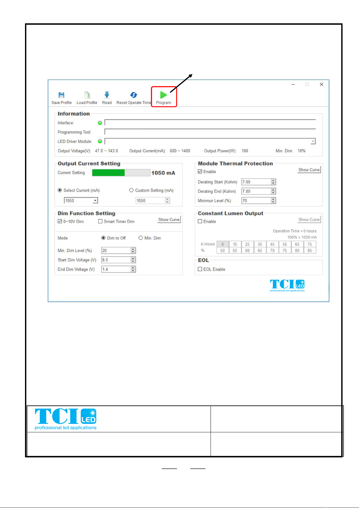
Click the “Program” button to start programming, and all the settings will be programmed
into the LED driver.
Click to program
FPD PROGRAMMING TOOL
User Manual
THESE DRAWINGS AND SPECIFICATIONS ARE THE PROPERTY OF TCI
AND SHALL NOT BE REPRODUCED OR USED AS THE BASIS FOR THE
MANUFACTURE OR SELL OF APPARATUSES OR DEVICES WITHOUT
PERMISSION.
FPD PROGRAMMING TOOL
FPD PROGRAMMING TOOL
VEGA 100/600-1400 FPD IP67

REV. : 2.0.0
SHEET 14 of 17
When the programming has started, the programming view pops up and the message
"Start Programming LED Driver ……" is displayed.
FPD PROGRAMMING TOOL
User Manual
THESE DRAWINGS AND SPECIFICATIONS ARE THE PROPERTY OF TCI
AND SHALL NOT BE REPRODUCED OR USED AS THE BASIS FOR THE
MANUFACTURE OR SELL OF APPARATUSES OR DEVICES WITHOUT
PERMISSION.
FPD PROGRAMMING TOOL
FPD PROGRAMMING TOOL
VEGA 100/600-1400 FPD IP67

REV. : 2.0.0
SHEET 15 of 17
When the programming is completed, the message “Programmed successfully….!” or
“Programmed Failed….!” will be displayed on the programming view, and automatically
count the number of “Prog. Success” or ”Prog. Failure”.
FPD PROGRAMMING TOOL
User Manual
THESE DRAWINGS AND SPECIFICATIONS ARE THE PROPERTY OF TCI
AND SHALL NOT BE REPRODUCED OR USED AS THE BASIS FOR THE
MANUFACTURE OR SELL OF APPARATUSES OR DEVICES WITHOUT
PERMISSION.
FPD PROGRAMMING TOOL
FPD PROGRAMMING TOOL
FPD PROGRAMMING TOOL
FPD PROGRAMMING TOOL
VEGA 100/600-1400 FPD IP67
VEGA 100/600-1400 FPD IP67

REV. : 2.0.0
SHEET 16 of 17
If the LED driver is not connected, the programming view will display the message
“Wait for LED Driver....!”. At this time, you can connect the next LED driver to continue
programming, or click the "Done" button to close the programming view.
FPD PROGRAMMING TOOL
User Manual
THESE DRAWINGS AND SPECIFICATIONS ARE THE PROPERTY OF TCI
AND SHALL NOT BE REPRODUCED OR USED AS THE BASIS FOR THE
MANUFACTURE OR SELL OF APPARATUSES OR DEVICES WITHOUT
PERMISSION.
FPD PROGRAMMING TOOL
FPD PROGRAMMING TOOL
VEGA 100/600-1400 FPD IP67

REV. : 2.0.0
SHEET 17 of 17
Function 5:
Read and check
The Read function will help the user to read the parameters/profile of the LED driver and
use the information.
When the LED driver is connected, click the "Read" button will start reading.
FPD PROGRAMMING TOOL
User Manual
THESE DRAWINGS AND SPECIFICATIONS ARE THE PROPERTY OF TCI
AND SHALL NOT BE REPRODUCED OR USED AS THE BASIS FOR THE
MANUFACTURE OR SELL OF APPARATUSES OR DEVICES WITHOUT
PERMISSION.
FPD PROGRAMMING TOOL
FPD PROGRAMMING TOOL
VEGA 100/600-1400 FPD IP67
This manual suits for next models
1
Table of contents


