TCi MFC A User manual

MFC Sine Wave Filter Kit
Installation Instructions
TCI, LLC
W132 N10611 Grant Drive
Germantown, Wisconsin 53022
Phone: 414-357-4480
Fax: 414-357-4484
Helpline: 800-TCI-8282
Web Site: http://www.transcoil.com
© 2020 TCI, LLC All rights reserved
Effective: 10/22/2020 Version: G


Revision
Description
Date
A
Release
09/27/2016
B
Update to drawings, heat loss
08/07/2018
C
Update to drawings and cooling
12/13/2018
D
Various text updates; added
Maintenance and Service section and
PQconnect option
04/09/2019
E
Updates to PQconnect section
01/09/2020
F
Updates to wiring notes
08/04/2020
G
Updates to PQconnect section
10/22/2020
No part of this publication may be reproduced, stored in a retrieval system, or transmitted in
any form or by any means, mechanical, electronic, photocopying, recording, or otherwise,
without the prior written permission of TCI, LLC. The information in this manual is subject to
change without notice. Every precaution has been taken in the preparation of this manual.
TCI, LLC assumes no responsibility for errors or omissions. Neither is any liability assumed
for damages resulting from the use of the information contained in this publication.

1
Table of Contents
1.0 Introduction .............................................................................................................................3
Safety Instructions Overview............................................................................................................. 3
Warnings and Cautions..................................................................................................................... 3
General Safety Instructions............................................................................................................... 4
2.0 General Information ................................................................................................................5
Intended Audience ............................................................................................................................ 5
Receiving Inspection......................................................................................................................... 5
Storage Instructions .......................................................................................................................... 5
TCI Limited Warranty Policy.............................................................................................................. 5
3.0 Pre-Installation Planning ........................................................................................................7
Verify the Application......................................................................................................................... 7
Product Description........................................................................................................................... 7
Part Number Encoding...................................................................................................................... 8
MFC “A” Filter Kit – Sine Wave Filter Kit with damping resistor........................................................ 9
MFC “A” Filter Kit Part Number and Ratings................................................................................... 10
MFC “R” Filter Kit – Sine Wave Filter Kit without damping resistor ................................................ 11
MFC “R” Filter Kit Part Number and Ratings................................................................................... 11
MFC “P” Filter Kit – Sine Wave Filter Kit with PQconnect .............................................................. 12
MFC “P” Filter Kit Part Number and Ratings................................................................................... 13
Variable Frequency Drive Settings.................................................................................................. 13
Filter Schematic............................................................................................................................... 14
Capacitors ....................................................................................................................................... 16
Capacitor Brackets.......................................................................................................................... 17
Recommendations for MFC Kit Usage............................................................................................ 17
4.0 Installation .............................................................................................................................18
Installation Guidelines..................................................................................................................... 18
Select a Suitable Location............................................................................................................... 18
Mounting the Filter Kit ..................................................................................................................... 19
Power Wiring................................................................................................................................... 19
Line Reactor Wiring......................................................................................................................... 19
Wire Sizing ...................................................................................................................................... 20
5.0 PQconnect Option.................................................................................................................26
Product Description......................................................................................................................... 26
Installation ....................................................................................................................................... 26
Mounting.......................................................................................................................................... 26
Wiring .............................................................................................................................................. 28
Modbus RTU ................................................................................................................................... 30
PQvision PC application Screen Elements..................................................................................... 31
PCB Calibration Process................................................................................................................. 33
Register Map................................................................................................................................... 38
Example Application Using “Simply Modbus Master 8.1.0” ............................................................ 49
USPTL4 RS485 Converter Dip Switch settings .............................................................................. 50
6.0 Troubleshooting....................................................................................................................52
Troubleshooting............................................................................................................................... 52
Communication Problems............................................................................................................... 54
Debug Status Conditions ................................................................................................................ 55
Periodic Maintenance...................................................................................................................... 55
Evaluating MFC Sine Wave Filter Performance ............................................................................. 56

MFC Kit IOM 1.0 Introduction
3
1.0 Introduction
The information presented in this manual covers the MFC Sine Wave Filter Kit
only.
Safety Instructions Overview
This section provides the safety instructions which must be followed when installing, operating, and
servicing the MFC Filter Kit. If neglected, physical injury or death may follow, or damage may occur
to the filter or equipment connected to the filter. The material in this chapter must be read and
understood before attempting any work on, or with, the product.
The MFC Filter Kit is intended to be connected to the output terminals of a variable frequency drive
(VFD). An AC motor is connected to the output terminals of the MFC Kit and receives power from
the VFD through the MFC Filter Kit. The instructions, and particularly the safety instructions, for the
VFD, motor and any other related equipment must be read, understood and followed when working
on any of the equipment.
Warnings and Cautions
This manual provides two types of safety instructions. Warnings are used to call attention to
instructions that describe steps that must be taken to avoid conditions that can lead to a serious
fault condition, physical injury, or death.
Cautions are used to call attention to instructions that describe steps that must be taken to avoid
conditions that can lead to a malfunction and possible equipment damage.
Warnings
Readers are informed of situations that can result in serious physical injury and/or serious damage
to equipment with warning statements highlighted by the following symbols:
Warning
Dangerous Voltage Warning: warns of situations where
high voltage can cause physical injury and/or damage
equipment. The text next to this symbol describes ways
to avoid the danger.
Warning
General Warning: warns of situations that can cause
physical injury and/or damage equipment by means
other than electrical. The text next to this symbol
describes ways to avoid the danger.
Warning
Electrostatic Discharge Warning: warns of situations in
which an electrostatic discharge can damage
equipment. The text next to this symbol describes ways
to avoid the danger.
Cautions
Readers are informed of situations that can lead to a malfunction and possible equipment damage
with caution statements:
Caution
General Caution: identifies situations that can lead to a
malfunction and possible equipment damage. The text
describes ways to avoid the situation.
!
!
MFC Kit IOM 1.0 Introduction
4
General Safety Instructions
These safety instructions are intended for all work on the MFC Filter Kit. Additional safety
instructions are provided at appropriate points on other sections of this manual.
Warning
Be sure to read, understand, and follow all safety
instructions.
Warning
Only qualified electricians should carry out all electrical
installation and maintenance work on the MFC Filter Kit.
Warning
All wiring must be in accordance with the National
Electrical Code (NEC) and/or any other codes that apply
to the installation site.
Warning
Disconnect all power before working on the equipment.
Do not attempt any work on a powered MFC Filter Kit.
Warning
The MFC Filter Kit, drive, motor, and other connected
equipment must be properly grounded.
Warning
After switching off the power, always allow 5 minutes for
the capacitors in the MFC Filter Kit and in the drive to
discharge before working on the MFC Kit, the drive, the
motor, or the connecting wiring. It is a good practice to
check with a voltmeter to make sure that all sources of
power have been disconnected and that all capacitors
have discharged before beginning work.
!
!
!

MFC Kit Instructions 2.0 General Information
5
2.0 General Information
Thank you for selecting the MFC Filter Kit. TCI has produced this filter for use in many VFD
applications that require output voltage filtering. This manual gives an overview of how to install,
operate and maintain the MFC Filter Kit. Please contact TCI Technical Support or visit
https://transcoil.com/Support for additional information
Intended Audience
This manual is intended for use by all personnel responsible for the assembly, wiring installation,
operation and maintenance of the MFC Filter Kit. Such personnel are expected to have knowledge of
electrical wiring practices, electronic components and electrical schematic symbols. Panel design using
a TCI MFCFilter Kit should be performed with appropriateengineering supervisionso the design meets
the requirements based on materials utilized in the construction of the panel, wiring practices followed
by your shop, and the actual ambient conditions of the components for each application.
Receiving Inspection
The MFC Filter Kit has been thoroughly inspected at the factory and carefully packaged for
shipment. When you receive the unit, you should immediately inspect the shipping container and
report any damage to the carrier that delivered the unit. Verify that the part number of the
components you received is the same as the part numbers listed on the engineering drawings for
the kit which can be found at:
https://transcoil.com/products-kmg-mfcdrawings-htm/
Storage Instructions
If the MFC Filter Kit is to be stored before use, be sure that it is stored in a location that conforms
to published storage humidity and temperature specifications in this manual and on the applicable
technical drawings available at: transcoil.com. Store the unit in its original packaging.
TCI Limited Warranty Policy
TCI, LLC (“TCI”) warrants to the original purchaser only that its products will be free from defects
in materials and workmanship under normal use and service for a period originating on the date of
shipment from TCI and expiring at the end of the period described below:
Product Family
Warranty Period
KLR, KDR
For the life of the drive with which they are installed.
HGA, V1K, KLC,
KLCUL, KMG, MSD
One (1) year of useful service,
not to exceed 18 months from the date of shipment.
PFGuard, HGP, HGL,
HG7, HSD, KRF
Three (3) years from the date of shipment.
KCAP, KTR
Five (5) years from the date of shipment.
All Other Products
One (1) year of useful service, not to exceed 18 months from
the date of shipment.
The foregoing limited warranty is TCI’s sole warranty with respect to its products and TCI makes
no other warranty, representation, or promise as to the quality or performance of TCI’s products.
THIS EXPRESS LIMITED WARRANTY IS GIVEN IN LIEU OF AND EXCLUDES ANY AND ALL
EXPRESS OR IMPLIED WARRANTIES INCLUDING, WITHOUT LIMITATION, ANY IMPLIED
WARRANTY OF MERCHANTABILITY OR FITNESS FOR A PARTICULAR PURPOSE.
This warranty shall not apply if the product was:
a) Altered or repaired by anyone other than TCI;
b) Applied or used for situations other than those originally specified; or

MFC Kit Instructions 2.0 General Information
6
c) Subjected to negligence, accident, or damage by circumstances beyond TCI’s control,
including but not limited to, improper storage, installation, operation, or maintenance.
If, within the warranty period, any product shall be found in TCI’s reasonable judgment to be
defective, TCI’s liability and the Buyer’s exclusive remedy under this warranty is expressly limited,
at TCI’s option, to (i) repair or replacement of that product, or (ii) return of the product and refund
of the purchase price. Such remedy shall be Buyer’s sole and exclusive remedy. TCI SHALL NOT,
IN ANY EVENT, BE LIABLE FOR INCIDENTAL DAMAGES OR FOR CONSEQUENTIAL
DAMAGES INCLUDING, BUT NOT LIMITED TO, LOSS OF INCOME, LOSS OF TIME, LOST
SALES, INJURY TO PERSONAL PROPERTY, LIABILITY BUYER INCURS WITH RESPECT TO
ANY OTHER PERSON, LOSS OF USE OF THE PRODUCT OR FOR ANY OTHER TYPE OR
FORM OF CONSEQUENTIAL DAMAGE OR ECONOMIC LOSS.
The foregoing warranties do not cover reimbursement for removal, transportation, reinstallation, or
any other expenses that may be incurred in connection with the repair or replacement of the TCI
product.
The employees and sales agents of TCI are not authorized to make additional warranties about
TCI’s products. TCI’s employees and sales agent’s oral statements do not constitute warranties;
these shall not be relied upon by the Buyer and are not part of any contract for sale. All warranties
of TCI embodied in this writing and no other warranties are given beyond those set forth herein.
TCI will not accept the return of any product without its prior written approval. Please consult TCI
Customer Service for instructions on the Return Authorization Procedure.

MFC Kit Instructions 3.0 Pre-Installation Planning
7
3.0 Pre-Installation Planning
Verify the Application
MFC Filter Kit Rating
Make sure that the MFC Filter Kit is correct for the application. The voltage rating of the filter kit
must match the voltage and current rating of the connected drive. The horsepower and current
rating of the filter kit must be appropriate for the connected load.
Product Description
The MFC Filter kit is a low-pass sine wave filter designed and developed by TCI to deliver
conditioned power to motor loads driven by PWM drives at a variety of lead lengths. The MFC Kit
is available for 460/480 Volt and 575/600 Volt systems.
The MFC Filter kit is a passive filter connected in series with the output terminals of the variable
frequency drive. It is designed to remove the carrier frequency distortion from the output voltage
waveform. The use of this low-pass filter will result in a nearly pure sine wave voltage profile. This
design will reduce the effects of the reflected wave phenomenon, (dV/dt), such as insulation
damage or premature failure in motors, transformers, and VFD output cables. The MFC Filter Kit
will also reduce the effects of stray high frequency harmonic currents, thereby reducing VFD ground
fault problems and noise interference in transducer signals.
The MFC Filter Kit is suitable for all lead lengths extending as far as 15,000 feet.
The MFC Filter Kit consists of the following standard features and components:
•A TCI 3-phase line reactor specifically designed for high PWM ripple current from the
sine wave filter application
•High-endurance, PWM current ripple rated capacitors
•Capacitor bleeder resistors to ensure safe capacitor discharge upon filter shutdown.
•Brackets for mounting capacitors to a panel (only for kits above 50 Amps)
•Damping resistors (optional)
•PQconnect monitoring and communications (optional)

MFC Kit Instructions 3.0 Pre-Installation Planning
8
Table 1: MFC Sine Wave Filter Technical Specifications
Current Ratings
480 V: 5 –1200 Amps
600 V: 8 –750 Amps
Intermittent overload current of 150% for 1 minute / hour
VFD Output Voltage
480 V and 600 V, 3-phase, at fundamental base frequency configured to Volts
per Hz
VFD Output Frequency
Up to 80 Hz
VFD Carrier Frequency
2 kHz to 16 kHz
Filter Performance
Maximum peak voltage of output waveform
480 V models: 815 V
600 V models: 1,018 V
Maximum dV/dt of output waveform
480 V models: 5 V/μs
600 V models: 6 V/μs
Environmental Conditions
Maximum Elevation
6,600 ft (2,000 m), derating required for operation above this level
Operating Temp
-30°C (-22°F) to 50°C (122°F)
Cooling provisions required for operation above this temperature.
Ambient Storage Temp
-40°C (-40°F) to 50°C (122°F)
Maximum Humidity
95% non-condensing
Reference Technical Standards
Voltage Drop
3% at nominal voltage, frequency and rated current
Capacitors
High endurance design (no PCBs)
Agency Approvals
UL & cULus Listed
Part Number Encoding
The figure below indicates the significance of each character in the MFC part number. The example
part number MFC130AR designates an MFC kit that is rated 130A, 480 Volts and does not include
resistors.
Figure 1: MFC Kit Part Number Encoding
NOTE: Individualpart drawings for each component included in the MFC Filter Kits are found at:
https://transcoil.com/products-kmg-mfcdrawings-htm/

MFC Kit Instructions 3.0 Pre-Installation Planning
9
MFC “A” Filter Kit – Sine Wave Filter Kit with damping resistor
The MFC Filter Kit is a sine wave filter component package designed and developed by TCI to allow
qualified customers to build sine wave filters to for the output of VFDs. The filter components are
designed to filter out PWM switching ripple when applied correctly and following the schematic
connections used by TCI. The MFC Filter Kit is available for 480 Volt and 600 Volt systems. When
properly designed, assembled, and installed, the completed product is intended to be suitable for use
with 3-phase PWM AC VFDs. The MFC A Filter Kit component package consists of the following
components:
•A KTRMG or KLRUL series filter reactor.
oThe 480 V/900 HP and larger units include two reactors that need to be wired in
parallel.
•High-endurance, PWM ripple current rated capacitors.
oBleeder resistors to ensure safe capacitor discharge on filter shutdown, located on
capacitors.
•Damping resistors
oHigh power 3-phase damping resistors to reduce VFD control or load dynamic
induced resonances. Damping resistors are recommended for applications which
have dynamically changing loads like hoists, elevators, or servos.
•Capacitor mounting brackets
oCapacitor mounting brackets are provided on kits rated 50 Amps and higher.
oKits under 50 Amps are not provided with capacitor brackets because these units
utilize single phase capacitors that do not have mounting brackets available for
them. These small size single phase capacitors are typically mounted vertically
due to the small size and reduced use of panel space.
MFC Kit Instructions 3.0 Pre-Installation Planning
10
MFC “A” Filter Kit Part Number and Ratings
480 Volt MFC Kit
HP
Amp
480 Volt Model
5
8
MFC008AA
7.5
12
MFC012AA
10
16
MFC016AA
15
23
MFC023AA
20
30
MFC030AA
25
35
MFC035AA
30
45
MFC045AA
40
55
MFC055AA
50
65
MFC065AA
60
80
MFC080AA
75
110
MFC110AA
100
130
MFC130AA
125
160
MFC160AA
150
200
MFC200AA
200
250
MFC250AA
250
305
MFC305AA
300
362
MFC362AA
350
420
MFC420AA
400
480
MFC480AA
450
540
MFC540AA
500
600
MFC600AA
600
750
MFC750AA
700
850
MFC850AA
800
960
MFC960AA
900
1080
MFC1080AA
1000
1200
MFC1200AA
575/600 Volt MFC Kit
HP
Amp
575/600 Volt Model
5
8
MFC008CA
7.5
10
MFC010CA
10
12
MFC012CA
15
20
MFC020CA
20
25
MFC025CA
25
28
MFC028CA
30
35
MFC035CA
40
45
MFC045CA
50
55
MFC055CA
60
65
MFC065CA
75
80
MFC080CA
100
110
MFC110CA
125
130
MFC130CA
150
160
MFC160CA
200
200
MFC200CA
250
250
MFC250CA
300
305
MFC305CA
350
362
MFC362CA
400
420
MFC420CA
450
450
MFC450CA
500
500
MFC500CA
600
600
MFC600CA
750
750
MFC750CA

MFC Kit Instructions 3.0 Pre-Installation Planning
11
MFC “R” Filter Kit – Sine Wave Filter Kit without damping resistor
The MFC Filter Kit is a sine wave filter component package designed and developed by TCI to allow
qualified customers to build sine wave filters to for the output of VFDs. The filter components are
designed to filter out PWM switching ripple when applied correctly and following the schematic
connections used by TCI. The MFC Filter Kit is available for 480 Volt and 600 Volt systems. When
properly designed, assembled, and installed, the completed product is intended to be suitable for use
with 3-phase PWM AC VFDs.
The MFC “R” Filter Kit component package consists of the following components:
•A KTRMG or KLRUL series filter reactor.
oThe 480 V/900 HP and larger units include two reactors that need to be wired in
parallel.
•High-endurance, PWM ripple current rated capacitors.
oBleeder resistors to ensure safe capacitor discharge on filter shutdown, located on
capacitors.
•Capacitor mounting brackets
oCapacitor mounting brackets are provided on kits rated 50 Amps and higher.
oKits under 50 Amps are not provided with capacitor brackets because these units
utilize single phase capacitors that do not have mounting brackets available for them.
These small size single phase capacitors are typically mounted vertically due to the
small size and reduced use of panel space.
•Note: There are no damping resistors included, these kits are most suitable for VFD
applications with low load and VFD dynamics
MFC “R” Filter Kit Part Number and Ratings
480 Volt MFC Kit
HP
Amp
480 Volt Model
5
8
MFC008AR
7.5
12
MFC012AR
10
16
MFC016AR
15
23
MFC023AR
20
30
MFC030AR
25
35
MFC035AR
30
45
MFC045AR
40
55
MFC055AR
50
65
MFC065AR
60
80
MFC080AR
75
110
MFC110AR
100
130
MFC130AR
125
160
MFC160AR
150
200
MFC200AR
200
250
MFC250AR
250
305
MFC305AR
300
362
MFC362AR
350
420
MFC420AR
400
480
MFC480AR
450
540
MFC540AR
500
600
MFC600AR
600
750
MFC750AR
700
850
MFC850AR
800
960
MFC960AR
900
1080
MFC1080AR
1000
1200
MFC1200AR
575/600 Volt MFC Kit
HP
Amp
575/600 Volt Model
5
8
MFC008CR
7.5
10
MFC010CR
10
12
MFC012CR
15
20
MFC020CR
20
25
MFC025CR
25
28
MFC028CR
30
35
MFC035CR
40
45
MFC045CR
50
55
MFC055CR
60
65
MFC065CR
75
80
MFC080CR
100
110
MFC110CR
125
130
MFC130CR
150
160
MFC160CR
200
200
MFC200CR
250
250
MFC250CR
300
305
MFC305CR
350
362
MFC362CR
400
420
MFC420CR
450
450
MFC450CR
500
500
MFC500CR
600
600
MFC600CR
750
750
MFC750CR

MFC Kit Instructions 3.0 Pre-Installation Planning
12
MFC “P” Filter Kit – Sine Wave Filter Kit with PQconnect
The MFC Filter Kit is a harmonic filter component package designed and developed by TCI to allow
qualified customers to build sine wave filters to for the output of VFDs. The filter components are
designed to filter out PWM switching ripple when applied correctly and following the schematic
connections used by TCI. The MFC Filter Kit is available for 480 Volt and 600 Volt systems. When
properly designed, assembled, and installed, the completed product is intended to be suitable for use
with 3-phase PWM AC VFDs.
The MFC “P” Filter Kit component package consists of the following components:
•A KTRMG or KLRUL series filter reactor.
oThe 480 V/900 HP and larger units include two reactors that need to be wired in
parallel.
•High-endurance, PWM ripple current rated capacitors.
oBleeder resistors to ensure safe capacitor discharge on filter shutdown, located on
capacitors.
•Capacitor mounting brackets
oCapacitor mounting brackets are provided on kits rated 50 Amps and higher.
oKits below 50 Amps are not provided with capacitor brackets because these units
utilize single phase capacitors that do not have mounting brackets available for them.
These small size single phase capacitors are typically mounted vertically due to the
small size and reduced use of panel space.
•PQconnect connectivity option
oModbus RTU over RS485 communications, preventative maintenance detection such
as peak overvoltage or high frequency output
•Note: There are no damping resistors included, these kits are most suitable for VFD
applications with low load and VFD dynamics

MFC Kit Instructions 3.0 Pre-Installation Planning
13
MFC “P” Filter Kit Part Number and Ratings
480 Volt MFC Kit
HP
Amp
480 Volt Model
5
8
MFC008AP
7.5
12
MFC012AP
10
16
MFC016AP
15
23
MFC023AP
20
30
MFC030AP
25
35
MFC035AP
30
45
MFC045AP
40
55
MFC055AP
50
65
MFC065AP
60
80
MFC080AP
75
110
MFC110AP
100
130
MFC130AP
125
160
MFC160AP
150
200
MFC200AP
200
250
MFC250AP
250
305
MFC305AP
300
362
MFC362AP
350
420
MFC420AP
400
480
MFC480AP
450
540
MFC540AP
500
600
MFC600AP
600
750
MFC750AP
700
850
MFC850AP
800
960
MFC960AP
900
1080
MFC1080AP
1000
1200
MFC1200AP
575/600 Volt MFC Kit
HP
Amp
575/600 Volt Model
5
8
MFC008CP
7.5
10
MFC010CP
10
12
MFC012CP
15
20
MFC020CP
20
25
MFC025CP
25
28
MFC028CP
30
35
MFC035CP
40
45
MFC045CP
50
55
MFC055CP
60
65
MFC065CP
75
80
MFC080CP
100
110
MFC110CP
125
130
MFC130CP
150
160
MFC160CP
200
200
MFC200CP
250
250
MFC250CP
300
305
MFC305CP
350
362
MFC362CP
400
420
MFC420CP
450
450
MFC450CP
500
500
MFC500CP
600
600
MFC600CP
750
750
MFC750CP
Variable Frequency Drive Settings
Make sure that the variable frequency drive will be set for operation modes and ranges that are
compatible with the MFC Kit:
•Maximum output frequency: 80 Hz
•Constant PWM switching (carrier) frequency between 2 kHz and 16 kHz, ideally 4
kHz to 8 kHz
•Mode of operation: speed control "scalar" or "V/Hz" without DC braking unless the drive
application has been confirmed by TCI Technical Support
•Consult VFD manual for other drive specific recommendations for use with sine wave
filters, specific instructions may include but are not limited to: disabling any variable PWM
switching frequency options such as features to reduce motor noise or control
temperature and setting drive to continuous 3-phase modulation.
Warning
Six-step operation is not compatible with sine wave filter technology.
!
MFC Kit Instructions 3.0 Pre-Installation Planning
14
Filter Schematic
The schematic shown in the figure below is an illustration of a typical MFC filter wiring.
Figure 2: Typical MFC “A” Filter Kit Wiring
*DISCONNECT NOT REQUIRED BY UL IF FILTER SUPPLIED BY LOAD SIDE OF POWER
CONVERSION EQUIPMENT (VFD)
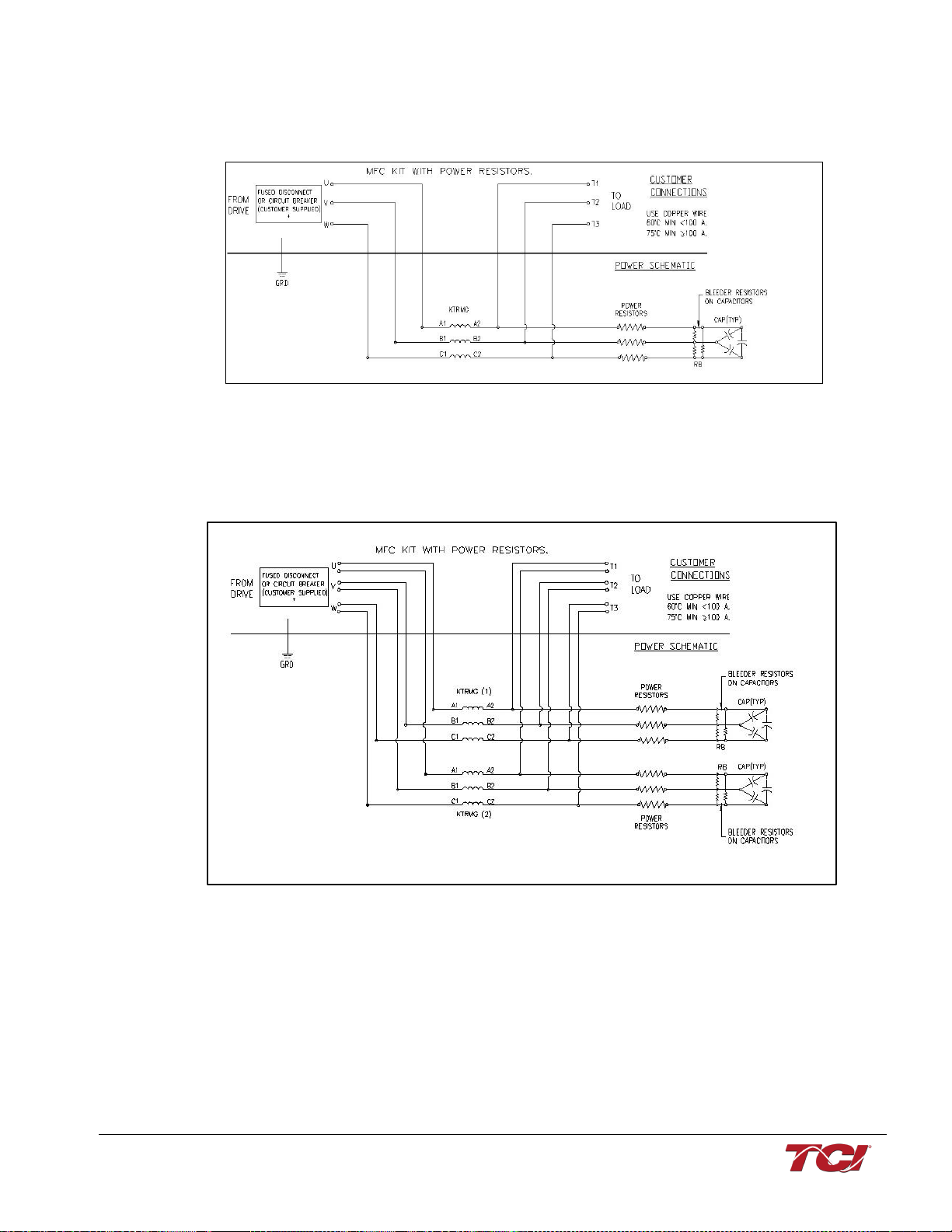
For horsepower ratings 480 V/ 900 HP and larger the series line reactor is comprised of two parallel
KTRMG reactors, as illustrated in the schematic below.
Figure 3: Typical MFC “A” Filter Kit Wiring for 480 V/900 HP and larger with two reactors
*DISCONNECT NOT REQUIRED BY UL IF FILTER SUPPLIED BY LOAD SIDE OF POWER
CONVERSION EQUIPMENT (VFD)

MFC Kit Instructions 3.0 Pre-Installation Planning
15
The schematic shown in the figure below is an illustration of a typical resistor-less MFC (AR, CR)
filter wiring.
Figure 4: Typical MFC “R” Filter Kit Wiring
*DISCONNECT NOT REQUIRED BY UL IF FILTER SUPPLIED BY LOAD SIDE OF POWER
CONVERSION EQUIPMENT (VFD)
For horsepower ratings 480 V/900 HP and larger the series line reactor is comprised of two parallel
KTRMG reactors, as illustrated in the schematic below.
Figure 5: Typical MFC “R” Filter Kit Wiring for 480 V/900 HP and larger with two reactors
*DISCONNECT NOT REQUIRED BY UL IF FILTER SUPPLIED BY LOAD SIDE OF POWER
CONVERSION EQUIPMENT (VFD)

MFC Kit Instructions 3.0 Pre-Installation Planning
16
The schematic shown in the figure below is an illustration of a typical MFC kit with PQconnect (AP,
CP) filter wiring.
Figure 6: Typical MFC “P” Filter Kit Wiring
*DISCONNECT NOT REQUIRED BY UL IF FILTER SUPPLIED BY LOAD SIDE OF POWER
CONVERSION EQUIPMENT (VFD)
Capacitors
The high-endurance, PWM current ripple rated capacitors supplied in the MFC Filter kit are in
shunt with the load. In the case of the MFC “A” Filter Kit, the capacitors are wired in series with
the power resistors. If multiple capacitors are supplied with the kit, they are intended to be
connected in parallel with each other. Typically, the capacitors are three-terminal, three-phase
capacitors with the internal capacitive elements connected in delta. Each capacitor has a bleeder
resistor connected across the three input terminals to ensure voltage discharges in the time
required by UL.
Warning
Do not connect capacitors to power unless the bleeder resistors are
connected, otherwise, hazardous voltages will remain across the
capacitors after the power has been disconnected.
Kits below 50 Amps are supplied with single phase capacitors for each filter.
These capacitors are connected in wye, and the bleeder resistors are connected across the
terminals of each capacitor.
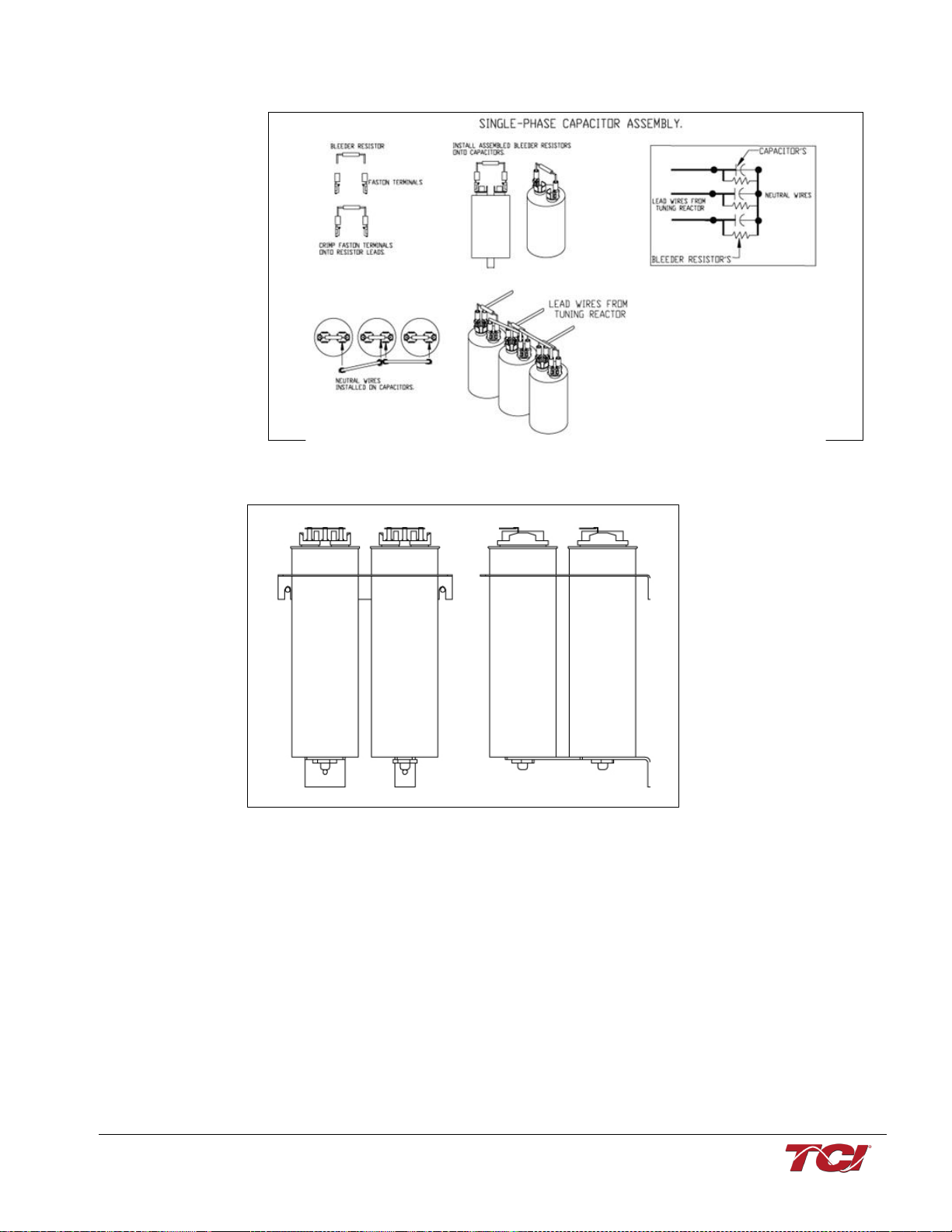
MFC Kit Instructions 3.0 Pre-Installation Planning
17
Figure 7: Bleeder Resistor Installation and Wiring for Single Phase
Capacitor Brackets
Figure 8: Capacitors and Brackets
Capacitor brackets supplied with the MFC kits (50 Amps and above) mount the three-phase capacitors
cansfromaright-anglebracket usingthestudsonthebottomofthecapacitors.Thebracketsurrounding
the capacitors is mounted near the top of the capacitor can. Grommet material is placed around the
large diameter holes to prevent the edges of the bracket damaging the capacitor cans. This hole does
not firmly clamp the capacitors and is not intended to do so: such a design would prevent the internal
capacitor pressure disconnection means from operating. This bracket prevents gross motion of the
capacitors during shipping vibration which could fracture the mounting bracket or allow the capacitors
to hit other components.
Recommendations for MFC Kit Usage
Panel design using a TCI MFC Filter Kit should be performed with appropriate engineering
supervision, so the design meets the requirements based on materials utilized in the construction
of the panel, wiring practices followed by your shop, and the actual ambient conditions of the
components for each application.
This manual suits for next models
2
Table of contents
Other TCi Water Filtration System manuals


