TCS SZ1063 User manual

2800 LAURA LANE • MIDDLETON, WI 53562 • (800) 288-9383 • FAX (608) 836-9044 • www.tcsbasys.com
1
SZ1063/SZ1064
Modulating Fan Coil
Thermostats
Product Manual
Description
The SZ1064 is a microprocessor based programmable
modulating fan coil thermostat and the SZ1063 is a non-
programmable modulating fan coil thermostat.
Features
• Stand-aloneornetworkoperation
• Nobatterybackuprequired
• Minimumon/offtimesforHVACequipmentprotection
• 32-characterLCDdisplay
• SixstatusLEDs
• Remoteroomsensingcapability
• Usersetpointadjustmentlimits
• Threespeedfan
• Systemandfanswitchingwithaccesslockouts
• Externalinputforsetbackoraquastatchangeover
• Accesstoprogrammingmaybelockedoutorlimited
withtheuseofanaccesscode
• FahrenheitorCelsiustemperaturedisplay
• Controlfortwoorfourpipesystems
• 7-dayprogrammabletimeclock
• Optionalpipesensorinputsforchangeover(SZ1064
only)
• Adjustabledelayonstart-upandpower-upforsoft
starts
• Smartrecovery(SZ1064only)
• Localandremoteoverridecapability
• Externaltimeclockandoverrideoptions
• Auxiliaryoutputforheat,coolortimeclock(SZ1064
only)
Contents
Description . . . . . . . . . . . . . . . . . . . . . . . . . . . . . . . . . . 1
Features ....................................1
Mounting ...................................1
Wiring ......................................2
Setup ......................................3
Programming ................................3
SettingClock&Schedule.......................6
SequenceofOperation ........................6
Checkout&Troubleshooting ....................8
LEDDescription ..............................9
LimitingOccupantAccess ......................10
UserGuide ..................................10
Mounting
TheSZ1063and64aredesignedforwallmounting
usingtwo#6sheetmetalscrews,eitheroverahorizon-
tallyinstalled2"x4"junctionbox,ordirectlytoblockor
drywall.
Forbestresults,thethermostatshouldbemountedon
aninteriorwallwhichreflectsnormalroomenvironment,
ataheightofapproximatelyfivefeetfromthefloor.
Avoidareasexposedtodirectsunlight,unusualheat
orcoolsources,opendoorsandwindows,unventilated
locations and hot or cold air from diffusers.
Ifusingaremoteroomsensor,itshouldbemountedin
themannerdescribedabove.Thethermostatmaythen
bemountedinanareawhichisaccessibleforadjusting
its settings.
Caution:Removepowerfromthermostatpriorto
mounting.
Communicating Thermostats
SZ1063 has been discontinued January 2013

2800 LAURA LANE • MIDDLETON, WI 53562 • (800) 288-9383 • FAX (608) 836-9044 • www.tcsbasys.com
2
Wiring
The SZ1063 and SZ1064 use standard terminal desig-
nationsfor wiring.Seediagrambelow.
REMOTE SENSOR WIRING
TheSZ1063acceptsone1000ohmtwo-wireplatinum
sensorandtheSZ1064acceptstwo.UseTS1009,
TS1002withTQSeriesImmersionwellsorTS1005for
watertemperaturesensing.
WhenusingTCS/BasysControlsthree-wiresensors,use
theblackandredleads,andeithercliportwistoffthe
whitelead.Thewiringlengthshouldnotexceed250ft.
POWERING THE SZ1064
Superstatsarepoweredfrom24VAC+/-20%.
Ifwiringforcommunications,dedicatedpowermustbe
usedtopowertheSuperstat.Several“S”Seriesther-
mostatsmaybepoweredfromthesametransformer,
providedthatthetransformerhassufficientpower.
(Superstatsrequire8VA@24VAC.)
Caution:Donotconnectto120VAC.When
multipleTCS/BasysControlsdevicesareusing
asingletransformer,thepolarityofthepower
wiringmustbemaintainedbecauseallTCS
devicesarehalf-waverectifiedandhavecom-
mon return paths.
When the Superstat is used as a stand-alone thermostat
withoutcommunications,theunittransformermaybe
usedtopowerit.Todothis,installajumperbetween
the“R”and“+24”terminals.The“24-”terminalmust
then be connected to the common side of the unit trans-
former.
Black
1Forcommunicationwiring,usetwisted,
shielded18AWG.Mustberunseparately.
2Drymomentarycontct.Mustnotbe
powered.
324VACtransformer.Seepowering
instructions.
4
5Sensorinputwiring18AWG,twisted,shieldedpair.
Drycontact.Mustnotbepowered.
6
4to20mAoutput600ohmmax.Donotpower
actuatorwithpowerfromthethermostat.The
thermostatsarehalf-waverectified,wherebythe
powergroundiscommonwiththesignalground.
3
4 4
4
5 5
Remote
Zone/Return
Air Temp
Pipe Temp
(SZ1064 only)
2
REFAB
Uptonominal28VACfromequipmenttransformer.
Black
Red
Red
Input Wiring for the SZ1063 and SZ1064
A B
R
1
G
Low
G
Med
CWV
+
-
6
HWV
+
-
6
7
REF
REF AB
G
Hi
RGLGMGH
Aux. Relay
Output
(SZ1064 only)
Output Wiring for the SZ1063 and SZ1064
* When heating and cooling on
atwo-pipeunit,useAO2
**Whenheatingonlyona
two-pipeunit,useAO1
***Whencoolingonlyona
two-pipeunit,useAO2
****Add500
Ω
resistor(included
inbag)toconvert0/4to20mA
to,0/2to10VDC.
*
*** **
****
****

2800 LAURA LANE • MIDDLETON, WI 53562 • (800) 288-9383 • FAX (608) 836-9044 • www.tcsbasys.com
3
Setup
Note:Ifusingremotesensor(s),thecalibrationmayneed
tobeadjusted.See“CheckoutandTroubleshooting”
section.
TEMPERATURESENSORSELECTION
Thedipswitchesinthecover(shownabove)mustbeset
whenusingremoteroom,and/orpipetempsensors.
Usethefollowingguidetodeterminethedipswitch
settingsforyourapplication.
Usingbuilt-inroomsensoronly.
(Thisisthedefaultsetting.)
Usingbuilt-inroomsensorwith
pipesensoronly.(SZ1064only)
Usingremoteroomsensoronly.
Usingremoteroomsensorwith
pipesensoronly.(SZ1064only)
Oncethedipswitcheshavebeen
setandyouhaveconfirmedthat
thesensorsarereadingcorrectly,
securethecovertothebasewith
thetwosetscrewslocatedatthetoprightandtheleft
sidetoprevent
tampering.
Programming
TheSZ1063andSZ1064maybeprogrammedthrough
thekeypadontheface,orwithaPC.
IfprogrammingwithaPC,thefollowingmustbeset
through the face prior to programming:
•Address(step#18)
•Baudrate(step#19)
•Temperaturescale(step#20)
FormoreinformationonprogrammingthroughthePC,
consultyourTCSsoftwaremanual.
PROGRAMMINGTHROUGHTHEKEYPAD
Toaccesstheprogrammingscreens,presstheprogram
setupbutton.ScreensAthruFaremonitoringscreens
program
setup
program
setup
BRANCHTOCLOCK/
10.
SCH.MENU? YES
ENTERACCESS
000
CODE
9.
NO
OVERRIDEON
178MINUTES
F.
program
setup
MODOUT100%
MODOUT200%
E.
program
setup
program
setup
PIPETEMP:
D.
150F
DI3OPEN
OFF
AUXRELAY
C.
program
setup
program
setup
DI2OPEN
DI1OPEN
B.
program
setup
A. WEDFAN:MED
3:27PM 82F
1 2 3 4 5
Main Monitoring Screen. Press the
program setup button to access the follow-
ing screens. (Day and date not shown on
SZ1063)
Digital Input 1 & 2 Status Screen.
Shows the status of DI1& DI2.
Digital Input 3 Status & Auxiliary
Relay Output Screen. Shows the
status of DI3. Shows the status of the
auxiliary relay output. This can be either
a timeclock output, a stage of heat or a
stage of cool. (Aux. output on SZ1064
only)
Pipe Temperature Screen. Shows
the pipe temperature if a pipe tem-
perature sensor is used. (SZ1064 only)
Modulating Output 1 & 2 Status
Screen. Shows the percentage of mod-
ulating output 1 (heat) & output 2 (cool).
Override Status Screen. Shows the
status of the first and second stages of
heating.
high
Occupied
Heating
Cooling
Data / Program
Service
COOLER
WARMER
Fan
fan
medium
fan
low
fan
fan
off
program
setup
OVERRIDE

2800 LAURA LANE • MIDDLETON, WI 53562 • (800) 288-9383 • FAX (608) 836-9044 • www.tcsbasys.com
4
program
setup
program
setup
TEMPSSHOWNIN:
14.
FAHRENHEIT
SETBAUDRATE:
9.6K
13.
11.
WEDFAN:MED
3:27PM
A:08:00 TO17:00
B:00:00 TO00:00
9.
SETOCCUPIED
7.
TIMESTUESDAY
A:08:00 TO17:00
B:00:00 TO00:00
5.
TIMESMONDAY:
SETOCCUPIED
4.
3.
SETTIME&DAY
3:27PM
COPYMONFOR
TUE?
8.
12.
SETADDRESS:
THU
NO
82F
000
C:00:00 TO00:00
D:00:00 TO00:00
6.
program
setup
program
setup
program
setup
C:00:00 TO00:00
D:00:00 TO00:00
10.
program
setup
program
setup
program
setup
program
setup
program
setup
program
setup
LIMITSETPOINT:
30.
ADJUST+/-: 05F
UNOCCUPIEDCOOL
80F
29.
24.
UNOCCUPIEDHEAT
SETPOINT:
SETUNOCCUPIED
18.
FANMODE: AUTO
SETOCCUPIEDFAN
SPEED: MED
17.
MODE: AUTO
SETOCCUPIEDFAN
16.
15.
SETSYSTEM
MODE:
SETUNOCCUPIED
FANSPEED:
19.
AUTO
MED
60F
SETPOINT:
OCCUPIEDHEAT
SETPOINTA: 70F
20.
OCCUPIEDHEAT
SETPOINTB: 70F
21.
OCCUPIEDHEAT
SETPOINTC: 70F
22.
OCCUPIEDHEAT
SETPOINTD: 70F
23.
25.
OCCUPIEDCOOL
75F
SETPOINTA:
26.
OCCUPIEDCOOL
75F
SETPOINTB:
27.
OCCUPIEDCOOL
75F
SETPOINTC:
28.
OCCUPIEDCOOL
75F
SETPOINTD:
program
setup
program
setup
program
setup
program
setup
program
setup
program
setup
program
setup
program
setup
program
setup
program
setup
program
setup
program
setup
program
setup
program
setup
program
setup
program
setup
Access Code Entry Screen. Will
appear if access code is required for pro-
gramming. Use 248 as the default. If the
wrong code is entered, it will revert to Screen
‘A’.
Programming or Clock / Schedule
Selection Screen. Choose YES here to
set the clock and schedule. Choose NO
here to perform all other programming
starting with step 1. (SZ1064 only)
Time and Day Screen. Set the hour,
minutes, AM or PM, and day
of the week. (SZ1064 only)
Schedule Announcement Screen.
Announces the next screen. (SZ1064 only)
Occupied Times Screen. Set the
hours and minutes of start and end times for
up to two occupied periods. (SZ1064 only)
Occupied Times Screen. Set the
hours and minutes of start and end times
for up to two occupied periods. (SZ1064
only)
Schedule Announcement Screen.
Announces the next screen. (SZ1064 only)
Copy Schedule Screen. Choose to
use the same schedule that was used for
the previous day. If so, the next screen
does not appear. (SZ1064 only)
Occupied Times Screen. Set the
hours and minutes of start and end times
for up to two occupied periods. (SZ1064
only)
Occupied Times Screen. Set the
hours and minutes of start and end times
for up to two occupied periods. (SZ1064
only)
Main Monitoring Screen.
When programming the Clock / Schedule,
this becomes the last screen. You will
need to start over by pressing program
setup and selecting NO at step 2 above to
continue to the Programming screens.
Controller Address Screen. If using
a PC to access the thermostat, set a unique
address from 0 to 255, excluding 248.
program
setup
program
setup
BRANCHTOCLOCK/
2.
SCH. MENU? YES
ENTERACCESS
000
CODE
1.
NO
OVERRIDEON
178MINUTES
F.
program
setup
MODOUT1 00%
MODOUT200%
E.
program
setup
program
setup
PIPETEMP:
D.
150F
DI3 OPEN
OFF
AUXRELAY
C.
program
setup
program
setup
DI2OPEN
DI1 OPEN
B.
program
setup
A.
WEDFAN:MED
3:27PM 82F
Communication Baud Rate Screen.
If using a PC to access the thermostat, all
controllers on a network must be set to the
same baud rate. Choose between 2.4K, 4.8K,
9.6K and 19.2K.
Display Type Screen. Choose between
FAHRENHEIT and CELSIUS for temperature
indication.
System Mode Screen. Choose from
AUTO, HEAT, COOL, or OFF for system
mode. In the OFF mode, all outputs are off.
Occupied Fan Mode Screen. Choose
between ON (continuous) or AUTO for your
fan run times during the occupied modes.
Occupied Fan Speed Screen. Choose
between LOW, MEDium and HIGH during
the occupied modes.
Unoccupied Fan Mode Screen.
Choose from AUTO or ON for your fan run
times in the unoccupied mode.
Unoccupied Fan Speed Screen.
Choose between LOW, MEDium and HIGH
during the unoccupied modes.
Occupied Heat Setpoint Screen.
Set the occupied heat setpoint.
Occupied Heat Setpoint Screen.
Set the occupied heat setpoint.
Occupied Heat Setpoint Screen.
Set the occupied heat setpoint.
Occupied Heat Setpoint Screen.
Set the occupied heat setpoint.
Unoccupied Heat Setpoint Screen.
Set the unoccupied heat setpoint.
Occupied Cool Setpoint Screen.
Set the occupied cool setpoint.
(Scheduling on SZ1064 only)
program
setup
program
setup
program
setup
TEMPSSHOWNIN:
14.
FAHRENHEIT
SETBAUDRATE:
9.6K
13.
11.
WEDFAN:MED
3:27PM
A:08:00 TO17:00
B:00:00 TO00:00
9.
SETOCCUPIED
7.
TIMESTUESDAY
A:08:00 TO17:00
B:00:00 TO00:00
5.
TIMESMONDAY:
SETOCCUPIED
4.
3.
SETTIME&DAY
3:27PM
COPYMONFOR
TUE?
8.
12.
SETADDRESS:
THU
NO
82F
000
C:00:00 TO00:00
D:00:00 TO00:00
6.
program
setup
program
setup
program
setup
C:00:00 TO00:00
D:00:00 TO00:00
10.
program
setup
program
setup
program
setup
program
setup

2800 LAURA LANE • MIDDLETON, WI 53562 • (800) 288-9383 • FAX (608) 836-9044 • www.tcsbasys.com
5
program
setup
program
setup
program
setup
program
setup
program
setup
program
setup
DI1 FOR
40.
COOLING: N.C.
AQUASTAT
DIGITAL
39.
37.
ENABLE2PIPE
SYSTEM?
ENABLE3 PIPE
FANCOIL?NO
36.
AUXRELAYOUTPUT
34.
TIMECLOCK
AUXRELAY
DIFF: 01F
33.
OFFSET: 01F
AUXRELAY
32.
31.
SETOVERRIDE
TIME: 180 MINTES
program
setup
program
setup
TIMECLOCKOUTPUT
OCCUPIED=
35.
program
setup
38.
SELECT2PIPE
program
setup
OPEN
NO
Cool
MODE:
program
setup
program
setup
program
setup
program
setup
program
setup
program
setup
MODOUT1 UNOCC
50.
ACTION: 0 or 4 mA
MODOUT2
0-20mA
49.
47.
MODOUT2
ACTION:
MODOUT1
ACTION: DIRECT
46.
MO1 SETPOINT
44.
OFFSET: 00F
MO2SETPOINT
BAND: 05F
43.
BAND: 05F
MO1 PROPORTIONAL
42.
41.
CHANGEOVER
SETPOINT: 090F
program
setup
program
setup
MO2SETPOINT
OFFSET:
45.
program
setup
48.
MODOUT1
program
setup
00F
DIRECT
RANGE: 0-20mA
RANGE:
Occupied Cool Setpoint Screen. Set the
occupied cool setpoint.
Occupied Cool Setpoint Screen. Set the
occupied cool setpoint.
Occupied Cool Setpoint Screen. Set the
occupied cool setpoint.
Unoccupied Cool Setpoint Screen. Set
the unoccupied cool setpoint.
User Setpoint Limit Screen. Enter the num-
ber of degrees you want the user to be allowed to
change the preset occupied setpoints up or down.
Override Time Screen. Enter the number of
minutes (0 to 255) that the thermostat will maintain
occupied setpoints when overridden.
Auxiliary Relay Offset Screen. Enter an
offset value for the auxiliary relay. This screen is
not used if step 26 is set to TIMECLOCK. (SZ1064
only)
Auxiliary Relay Differential Screen.
Enter a differential value for the auxiliary relay. This
screen is not used if step 26 is set to TIMECLOCK.
(SZ1064 only)
Auxiliary Relay Output Screen. Choose
whether the auxiliary output will be used for either a
TIMECLOCK output, a stage of HEAT or a stage of
COOL. (SZ1064 only)
Time Clock Output Screen. Choose wheth-
er the auxiliary output will be OPEN or CLOSED
during occupied periods. This screen is not used if
step 26 is set to HEAT or COOL. (SZ1064 only)
3-Pipe Fan Coil Enable Screen. Choose
YES if using a three-pipe system. Otherwise
choose NO. If YES is selected, skip to step 42.
2-Pipe Fan Coil Enable Screen. Choose
YES if using a two-pipe system. Otherwise choose
NO. If NO is selected, and skip to step 42 and it is
assumed to be a four-pipe system.
Digital Aquastat Input Screen. Choose
whether DI1 will be normally open (N.O.) or nor-
mally closed (N.C.) for cooling. The next screen
is skipped.
Analog Aquastat Input Screen. If an
analog aquastat is selected, choose the changeover
setpoint to distinguish when hot or cold water is
available. If the 'pipe' temperature is below this
setpoint, analog output 2 will do cooling. If the 'pipe'
temperature is above this setpoint, analog output 2
will do heating. (SZ1064 only)
Modulating Output 1 Proportional Band
Screen. Enter the number of degrees away from
the heating setpoint that the valve will be fully open.
Modulating Output 2 Proportional Band
Screen. Enter the number of degrees away from
the cooling setpoint that the valve will be fully open.
Modulating 1 Setpoint Offset Screen.
Enter an offset value for modulating output 1. This
is the number of degrees below the heating setpoint
before the output begins to modulate.
Modulating 2 Setpoint Offset Screen.
Enter an offset value for modulating output 2. This
is the number of degrees above the cooling setpoint
before the output begins to modulate.
Modulating 1 Output Action Screen.
Choose whether modulating output 1 will be direct
or reverse acting.
Modulating 2 Output Action Screen.
Choose whether modulating output 2 will be direct
or reverse acting.
Modulating Output 1 Range Screen.
Choose whether the modulating output 1 range will
be 0-20 mA or 4-20 mA.
LIMITSETPOINT:
30.
ADJUST+/-: 05F
UNOCCUPIEDCOOL
80F
29.
24.
UNOCCUPIEDHEAT
SETPOINT:
SETUNOCCUPIED
18.
FANMODE: AUTO
SETOCCUPIEDFAN
SPEED: MED
17.
MODE: AUTO
SETOCCUPIEDFAN
16.
15.
SETSYSTEM
MODE:
SETUNOCCUPIED
FANSPEED:
19.
AUTO
MED
60F
SETPOINT:
OCCUPIEDHEAT
SETPOINTA: 70F
20.
OCCUPIEDHEAT
SETPOINTB: 70F
21.
OCCUPIEDHEAT
SETPOINTC: 70F
22.
OCCUPIEDHEAT
SETPOINTD: 70F
23.
25.
OCCUPIEDCOOL
75F
SETPOINTA:
26.
OCCUPIEDCOOL
75F
SETPOINTB:
27.
OCCUPIEDCOOL
75F
SETPOINTC:
28.
OCCUPIEDCOOL
75F
SETPOINTD:
program
setup
program
setup
program
setup
program
setup
program
setup
program
setup
program
setup
program
setup
program
setup
program
setup
program
setup
program
setup
program
setup
program
setup
program
setup
program
setup
program
setup
program
setup
program
setup
program
setup
program
setup
program
setup
DI1 FOR
40.
COOLING: N.C.
AQUASTAT
DIGITAL
39.
37.
ENABLE2PIPE
SYSTEM?
ENABLE3 PIPE
FANCOIL?NO
36.
AUXRELAYOUTPUT
34.
TIMECLOCK
AUXRELAY
DIFF: 01F
33.
OFFSET: 01F
AUXRELAY
32.
31.
SETOVERRIDE
TIME: 180 MINTES
program
setup
program
setup
TIMECLOCKOUTPUT
OCCUPIED=
35.
program
setup
38.
SELECT2PIPE
program
setup
OPEN
NO
Cool
MODE:
2-Pipe Fan Coil Control Screen. For a
two-pipe fan coil, select whether it is a HEAT only
system, COOL only system, or whether the system
is capable of heating and cooling H&C. If HEAT or
COOL is selected, skip to step 42.
Aquastat Mode Screen. With a two-pipe
system choose whether the Aquastat function is
DIGITAL (DI1) or ANALOG (T2). If analog is select-
ed, skip to step 41 (SZ1064 only)

2800 LAURA LANE • MIDDLETON, WI 53562 • (800) 288-9383 • FAX (608) 836-9044 • www.tcsbasys.com
6
andprogrammingscreensbeginwith#1.Accessmay
belockedoutwithdipswitches,oranaccesscodemay
berequired.
SettingClock&Schedule
TheSZ1064clockandschedulemaybesetthroughthe
keypadanddisplay,orwithaPC.Formoreinformation
onprogrammingthroughthePC,consultyourTCSsoft-
waremanual.
SETTING CLOCK & SCHEDULE
THROUGH THE KEYPAD
Toaccesstheclockandschedulescreensinstep#2
selectyes.Tomakechanges,usethewarmerand
coolerkeys.Forscreensthathavemorethanonefield
toset,usetheoverridekeytomovetothenextfield.An
accesscodemayberequired.
Operation
UNOCCUPIED SETBACK
TheSZ1063andSZ1064operates,ineitheranoccu-
piedorunoccupiedmode.Duringtheoccupiedmode,
theoccupiedheatingandcoolingsetpointswillbemain-
tained,andthefanwilloperateaccordingtoitsoccupied
setting.Duringtheunoccupiedmode,theunoccupied
heatingandcoolingsetpointswillbemaintained,and
thefanwilloperateaccordingtoitsunoccupiedsetting.
TheoccupiedLEDwillbelitwhentheunitisoperating
in the occupied mode.
Theoccupiedschedulemaybesetutilizingtheinternal
timeclock(SZ1064only)orDI3maybeusedwithan
externaltimeclock,whereaswhenDI3isclosed,the
unitisintheoccupiedmode.TheSmartRecoveryfunc-
tionisdisabledwhenDI3isusedforexternaltimeclock.
OVERRIDE
Atimedoverrideisavailableusingthebuttononthe
faceofthethermostatorthroughmomentarycontacts
wiredintotheOVRterminal.Theamountoftimethe
unitwillbeoverriddenissetfrom0to255minutesin
theprogrammingscreen.Thisoverridebehavesdiffer-
entlydependingonthemodethethermostatisoperating
in(occupiedorunoccupied)andtheoptionsthathave
beenenabledwithinthesoftware.
Instandardmode,theoverrideonlyactivatesinunoc-
cupiedmodeandtakesthethermostatintooccupied
mode.If"OverrideforOccupiedPeriod"isenabledusing
thesoftware,theoverridealsoactivatesinoccupied
modeandtakesthethermostatintounoccupiedmode.
Ineithercase,youareabletoviewthetimeremain-
ingintheoverrideperiodbothwithinthesoftwareand
byusingtheservicebuttontoscrollthroughthestatus
screens. If the occupant desires to return the thermostat
tounoccupiedoroccupiedoperation(dependingonhow
theoverridewasused)beforetheoverridetimeremain-
ingelapses,theymaypresstheoverridebuttonagain.
Modulating Output 2 Range Screen.
Choose whether the modulating output 2 range will
be 0-20 mA or 4-20 mA.
Modulating Output 1 Unoccupied
Action Screen. Choose whether the modulat-
ing output 1 unoccupied action will be 0mA or 4mA,
20mA or MODulating.
Modulating Output 2 Unoccupied
Action Screen. Choose whether the modulat-
ing output 2 unoccupied action will be 0mA or
4mA, 20mA or MODulating.
DI2 Shift Screen. Enter the setpoint shift
value. This screen will only appear if DI2 is set to
MONITOR.
DI3 Choice Screen. Choose FILTER
SERVICE, EXTernal OVERRIDE, or EXTernal TIME
CLOCK. Select EXTernal OVERRIDE if unused.
(EXTernal OVERRIDE on SZ1064 only)
Delay On Powerup Screen. Enter a value
in seconds, such that when the unit is powered up
or on occupied startup, control is delayed for this
amount of time.
Smart Recovery Screen. Choose whether
or not smart recovery will be used. Note: Smart
Recovery is not available when DI3 is used as
EXTernal TIME CLOCK. (SZ1064 only)
Programming Access Screen. Choose
whether or not a code will be required to enter
programming setup.
Access Code Screen. Enter an access (0 to
255) code that will be used to enter the program-
ming setup if access code has been required in the
last two step. The default is 248.
Main Monitoring Screen.
program
setup
program
setup
program
setup
program
setup
program
setup
program
setup
MODOUT1 UNOCC
50.
ACTION: 0 or 4 mA
MODOUT2
0-20mA
49.
47.
MODOUT2
ACTION:
MODOUT1
ACTION: DIRECT
46.
MO1 SETPOINT
44.
OFFSET: 00F
MO2SETPOINT
BAND: 05F
43.
BAND: 05F
MO1 PROPORTIONAL
42.
41.
CHANGEOVER
SETPOINT: 090F
program
setup
program
setup
MO2SETPOINT
OFFSET:
45.
program
setup
48.
MODOUT1
program
setup
00F
DIRECT
RANGE: 0-20mA
RANGE:
program
setup
program
setup
program
setup
program
setup
57.
SETACCESS
CODE:
REQUIRECODEFOR
PROGRAMMING?YES
56.
DELAYONPOWERUP
54.
010 SECONDS
DI3 USEDFOR:
MONITOR
53.
SHIFT: 00F
SETDI2SETPOINT
52.
51.
MODOUT2UNOCC
ACTION: 0 or 4 mA
program
setup
program
setup
ENABLESMART
RECOVERY?
55.
58.
WEDFAN:MED
program
setup
YES
248
3:27PM 82F

2800 LAURA LANE • MIDDLETON, WI 53562 • (800) 288-9383 • FAX (608) 836-9044 • www.tcsbasys.com
7
Additionally,an"OverrideHold"featureisbuiltintothe
thermostats.Wheninunoccupiedmode,pressingthe
overrideonceandthenpressing/holdingitfor5seconds
putsthethermostatintoa"hold”mode(theoverrideLED
onthethermostatwillflashquicklytoconfirmthemode
change).Inthismode,theoverridesetpointsareused
untilthenextoccupiedperiodisreachedoruntilthether-
mostatismanuallytakenoutofthe"hold"modebypress-
ingtheoverridebuttonagain.Thisfeaturealsoworks
whenthe"OverrideforOccupiedPeriod"isenabledBUT
starting from the occupied mode and holding the thermo-
stat in the unoccupied state.
AcontinuousoverrideisavailablethroughtheDI3contact
orthesoftware.IfDI3issettoexternaloverride,theunit
willbeintheoccupiedmodewhenevertheDI3contactis
closed.Whenusingthisoption,thetimedoverridemay
stillbeactivated.
SETBACK AND OVERRIDE APPLICATIONS
Inmostapplications,itisdesiredtomaintainaregular
schedule,andallowtimedoverridewiththebuttononthe
faceorwitharemotemomentarycontact.
Toallowaregularschedule,andalsoautomaticallyover-
ridewiththeuseofoccupancyorlightsensor,setDI3to
overrideandsetitupsothatthecontactisclosedwhen
youwanttheoverride.
Forapplicationswherearoommightnotbeusedona
regularschedule,suchasconferencerooms,setDI3to
externaltimeclockandclosethecontactwhenyouwant
theroomoccupied,suchaswithaswitchorwind-up
timer.Ifeachoccupancyperiodisaboutthesame,(the-
aters,meetings)anotheroptionistosettheDI3toexter-
naltimeclock,andusethetimedoverridebuttontoput
the unit in occupied mode.
Tomaketheunitalwaysoccupied,setDI3toexternal
timeclockandshorttheDI3terminaltoground.
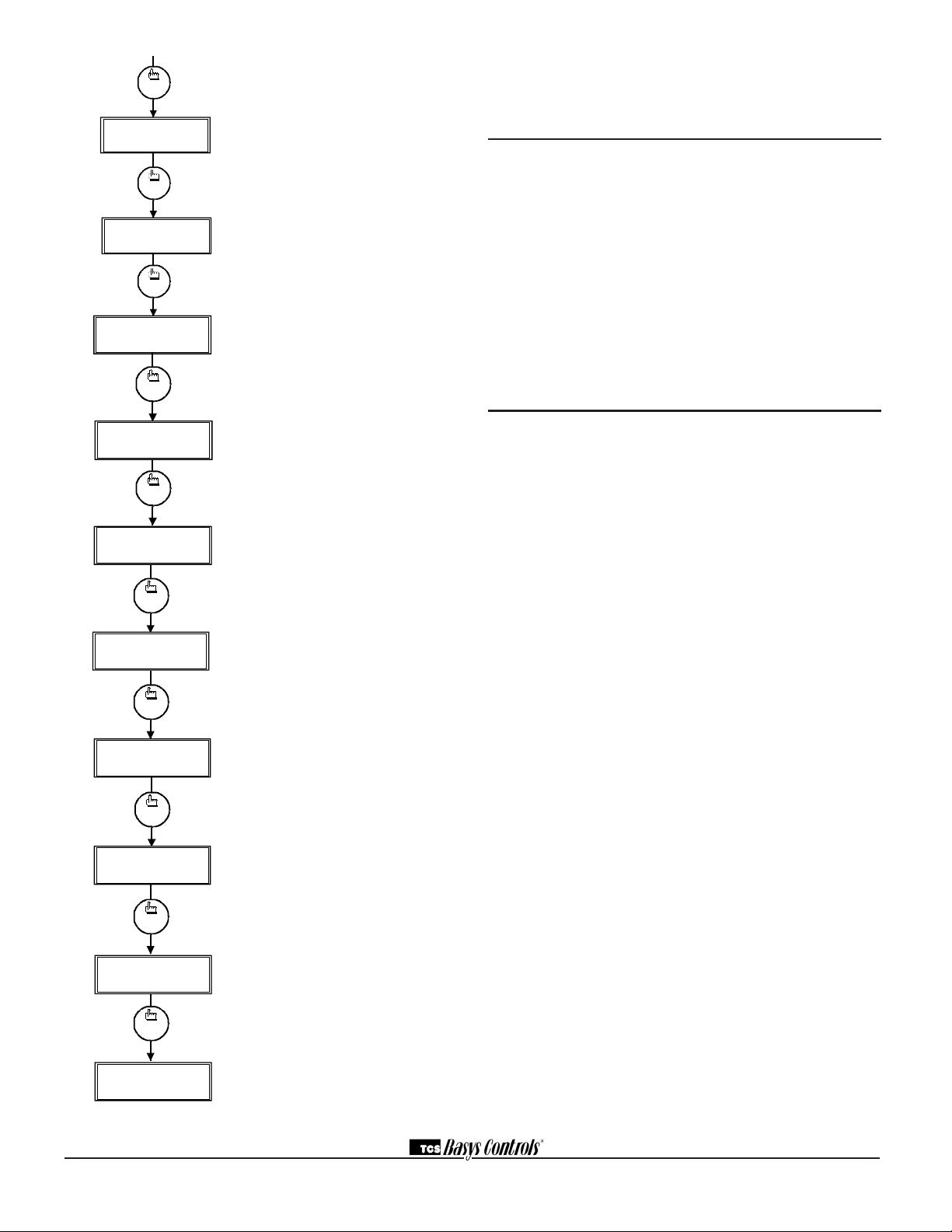
TWO-PIPE FAN COIL OPERATION
Fortwo-pipefancoiloperation,instep#28selectNO.In
step#29,selectYES.Youmustthenselectwhetherthe
systemisHEATingonly,COOLingonlyorheatingand
cooling(H&C)instep#30.
Whenusingatwo-pipesystemtodobothheatingand
cooling,theSZ1063andSZ1064needtoknowwhether
hotorcoldwaterisavailable.Thisisaccomplishedby
eithertheuseofamechanicalaquastat(bulbthermostat)
connectedtoterminalsDI1and24-,orbytheuseofa
temperaturesensorconnectedtoT2andT2(SZ1064
only).Ifusingamechanicalthermostat,selectDIGITAL
instep#31,andselectnormallyclosedN.C.ornormally
openN.O.Instep#32.Ifusingatemperaturesensor,
selectANALOGinstep#31andplaceachangeoverset-
pointinstep#33.Whenthetemperatureisgreaterthan
thissetpoint,itisassumedhotwaterisavailableand
heating is done. When the temperature is less than this
setpoint,itisassumedcoldwaterisavailableandcooling
is done.
Whenusingatwo-pipesystemtodobothheatingand
cooling,onlyAO2isused.Whenusingatwo-pipesys-
temtodoonlyheating,onlyAO1isused.Whenusinga
two-pipesystemtodoonlycooling,onlyAO2isused.
THREE-PIPE FAN COIL OPERATION
Forthree-pipefancoiloperation,instep#28selectYES.
Three-pipe fan coil operation assumes that there are
twowatersourcesavailable(hotandcold),andthat
thewatertothefancoilwillbeamixtureofthese.Only
analogoutputtwoisusedforthree-pipeoperation.The
outputwillbe12mA(4-20mA)whenthereisnoneedfor
heatingorcooling.Astherebecomesaneedforheating
orcooling,theanalogoutputmodulatestoward4mAor
20mAdependingonwhetheranalogoutputtwoisdirect
orreverseacting.
FOUR-PIPE FAN COIL OPERATION
Forfour-pipefancoiloperation,instep#28selectNO.
Instep#29,selectNO.
Four-pipefancoiloperationassumesthattherearetwo
watersourcesavailable(hotandcold),thatareeach
controlledbyitsownvalve.Analogoutputoneisused
forheatingandanalogoutputtwoisusedforcooling.
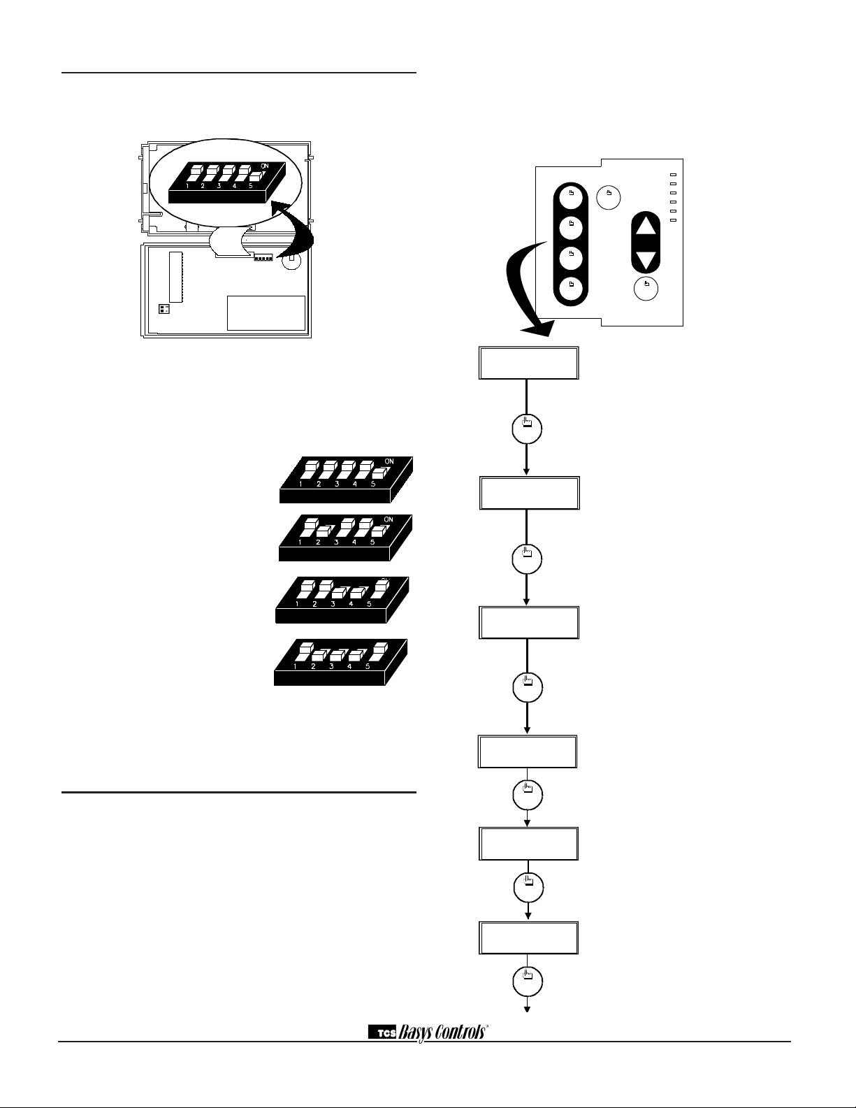
PIPE TEMPERATURE SENSING
The SZ1063 and SZ1064 accepts a remote pipe tem-
perature sensor for monitoring purposes or for change-
overinatwo-pipesystem.(Seesetupinstructionsfor
dipswitchplacementforthisoption.)
Thepipetemperaturespanis0to150°F(-17.8to
65.6°C).
ANALOG OUTPUTS
The analog outputs on the SZ1063 and SZ1064 are
used to control the heating and cooling in a space.
Analogoutput1isusedtocontrolheatingandanalog
twoisusedtocontrolcoolingwithafourpipesystem.
Onlyanalogoutput2isusedwithathree-pipeorwith
two-pipesystemsetforheatandcool(H&C).
DI2 SETPOINT SHIFT
TheSZ1063andSZ1064allowDI2tobesetforsetpoint
shiftforenergydemandsetback.Adigitalcontactthat
closeswhensetbackisneededshouldbewiredinto
DI2.Youmayspecifyanumberofdegreessuchthat,
whenthethermostatisoperatingintheoccupiedmode,
andDI2isclosed,theheatingsetpointwillbelowered
thisnumberofdegrees,andthecoolingsetpointwill
beraisedthisnumberofdegrees.Thefanwillcontinue
tooperateaccordingtoitsoccupiedsetting.Ifyouare
usingDI2asmonitorforanotherpurpose,makesureto
setthesetpointshiftvaluetozero.
AUXILIARY RELAY OUTPUT PARAMETERS
TheauxiliaryrelayoftheSZ1064willcontrolonestage
ofeitherheatingorcooling,orcanbeusedasatime-
clockoutput.

2800 LAURA LANE • MIDDLETON, WI 53562 • (800) 288-9383 • FAX (608) 836-9044 • www.tcsbasys.com
8
DI1 AQUASTAT
DI1isusedasanaquastatinputfortwo-pipefancoil
systems.
Itisselectableinprogrammingstep#32whethera
closed contact indicates cooling or an open contact indi-
cates cooling.
SMART RECOVERY
SmartRecoverymaybeenabled(SZ1064only).It
rampsthesetpoint4°F/hr.whengoingfromtheunoc-
cupiedandmodetotheoccupiedmode.Atthebegin-
ningoftheoccupiedmode,theoccupiedsetpointwillbe
reached,manytimeswithouttheneedforthesecond
stagetocomeon.Thisfeatureisautomaticallydisabled
whenDI3issettoexternaltimeclock.
BUILT-IN DELAYS
TheSZ1063andSZ1064havedelaysbuiltintothepro-
grammingsequencestoprotectequipment.Thefanhas
a minimum on and off time of 30 seconds. When the fan
isinAUTOmode,itwillcomeon30secondsbeforethe
heatingorcoolingdevicesareallowedtosequenceon.
Theauxiliaryrelay,whensettobeastageofheator
cool,hasaminimumonandofftimeoftwominutes.
DELAYONPOWERUP
TheSZ1063andSZ1064haveanadjustabledelayon
powerupandstart-up.Whenseveralthermostatsare
usedatonelocation,andthepowergoesout,mostther-
mostatsturnalloftheunitsbackonatthesametimeon
regainofpower,creatingapeak.Thethermostatallows
youtosetavalue,inseconds,wherenooutputsare
Iftheauxiliaryrelayisusedasheatingorcoolingstage,
youmayspecifyanoffsetandadifferentialvalue.The
offsetvalueistheamountawayfromthesetpointa
stagewillturnoff.Byassigningavalueotherthanzero,
you"anticipate"thattheresidualheatorcoolinginthe
ductwillbringthetemperaturebacktosetpoint.Inmost
cases,afirststageissettozero.Thedifferentialvalue
isthedifferencebetweentheonandoffpoints.Using
anoffsetvaluegreaterthanorequaltotheproportional
bandofananalogoutputwillallowtherelaytocomeon
afterfullmodulationisachieved.Stripheat,forexample.
Iftheauxiliaryrelayisusedasatimeclockoutput,itis
selectablewhethertherelayisopenorclosedduring
theoccupiedperiod.Duringtheunoccupiedperiod,the
oppositewilloccur.
Keepinmindthatalthoughitisanisolatedrelay(sepa-
ratecommonterminal),itisratedat24VAC@2A.For
loadsthatexceedthis,useanexternalrelay.
ANALOG OUTPUT PARAMETERS
Useprogrammingsteps#34through#43toprogram
the operating parameters for the analog outputs. Select
directorreverseaction.Selectwhetheryouwantthe
analogoutputtomodulatefrom4to20mAor0to20mA.
Selecttheunoccupiedaction("20mAor0/4mA"will
holdtheanalogoutputdeviceopenorclosedduring
unoccupiedtimes."Modulating"willmodulatetheana-
logoutputdevicetomaintaintheunoccupiedheatingor
coolingsetpoint.).Enteraproportionalband(throttling
range)indegrees.Enterasetpointoffsetindegrees.
(Thisisavaluebelowtheheatingsetpointorabove
thecoolingsetpointwheretheanalogoutputbeginsto
modulate.)
Heat
Setpoint
Cool
Setpoint
ON
ON
OFF
OFF
Differential
Differential
Offset
Offset
Aux. Relay Aux. Relay
Differential
ON
OFF
Cool
Differential
ON
OFF
Heat
420 420
420
420
420 420
P
Z
o
n
e
T
e
m
p
Output
(mA)
P
Output
(mA)
DIRECT ACTING REVERSE ACTING
PP
Output
(mA) Output
(mA)
Z
o
n
e
T
e
m
p
PP
Output
(mA) Output
(mA)
P
P
Z
o
n
e
T
e
m
p
CSP CSP
HSP HSP
CSP CSP
HSP HSP

2800 LAURA LANE • MIDDLETON, WI 53562 • (800) 288-9383 • FAX (608) 836-9044 • www.tcsbasys.com
9
allowedtoturnonforthatlengthoftimeonpowerup.
Settingeachunittoadifferentdelayallowsyoutosoft
startyoursystem,andthuspreventthispeak.Thisfunc-
tionalsooccurswhenanoccupiedperiodbeginsto
preventallunitsfromstartingatthesametime.
Checkout&Troubleshooting
CHECKOUT
1.Besuretocheckandverifyallwiringbeforepowering
the SZ1063 and SZ1064.
NOTE:Thefanhasaminimumonandofftimeof30
seconds.Theauxiliaryrelaywhensetforheatingor
coolinghasaminimumonandofftimeof2minutes.
NOTE:TheSZ1063doesnotshowthedayortime.
2.Turnpoweron.Thethermostatwilldisplayamomen-
taryscreenwiththemodelnumber,andthenthemain
monitoringscreenwiththetime,day,fanspeedandcur-
rent temperature.
3.PressthePROGRAMSETUPbuttonuntilyou
reachscreen#13andsettheSystemModetoAUTO.
Continueonuntilyoureachscreen#14andsetthe
OccupiedFanModetoAUTO.Gotoscreen#22
whichallowsyoutosettheoccupantsetpointadjust-
mentlimits.Changethisto+/-20°F(11.1°C).Press
thePROGRAMSETUPbuttononcemoretostorethe
change.ThenpresstheFANOFFbuttononcetoexit
the programming.
4.Verifythatthethermostatisoperatingintheoccupied
modebymakingsurethatthetopLEDislit.Ifnot,press
theOVERRIDEbutton.TheLEDshouldlightup.
5.Takenoteofthecurrenttemperaturereading.Press
theWARMER(up)button.Thesetpointadjustment
screenshouldnowbeshowing.PresstheWARMER
button until the heating setpoint is greater than the cur-
renttemperaturebyatleastfivedegrees.Thefanwill
comeon.Theauxiliaryrelayifsettoheatingwillcome
on after 30 seconds.
6.Pressthecooler(down)buttonuntiltheheatingset-
point is one degree less than the current temperature.
Theheatingstagewillsequenceoff.Thefanwillturnoff
2minutesafterwards.
7.Pressthecoolerbuttonuntilthecoolingsetpoint
islessthanthecurrenttemperaturebyatleastfive
degrees.Thefanwillcomeon.Theauxiliaryrelayifset
tocoolingwillcomeonafter30seconds.
8.Pressthewarmerbuttonuntilthecoolingsetpointis
greaterthanthecurrenttemperaturebyonedegree.The
coolingstagewillsequenceoff.Thefanwillturnoff2
minutesafterwards.
9.Foraheatingorcoolinganalogoutput:Takenoteof
theroom(anddischarge)airtemperatures.Iftheanalog
outputissetforCooling,presstheCoolerbuttonuntil
the cooling setpoint is less than the current room tem-
peraturebyatleast5°.Thecoolingdeviceshouldstart
operating.IftheanalogoutputissetforHeating,press
the Warmer button until the heating setpoint is greater
thanthecurrentroomtemperaturebyatleast5°.The
heatingdeviceshouldstartoperating.
10.Gobacktoprogrammingstep#22andsettheset-
pointadjustlimitbacktothedesiredvalue.Makeany
otherchangesinprogramming,clock,andschedule.Set
thefanandsystemmodestotheirdesiredsettings.
11.Ifusingremotesensor(s),verifythatthereading
iscorrect.Ifnot,seeWrongTemperatureDisplayin
Troubleshooting section.
TROUBLESHOOTING
No Display
Checkfor24VAConterminals"+24"and"-24".Check
thecableconnectingthecovertothebaseforagood
connection.
Fan Does Not Come On
ThefanisonwheneverthefanLEDison.Ifthefan
shouldbeon,butthefanLEDisoff,checktheoccupied
and unoccupied fan mode in programming. If the Fan
StatusisOFF,presstheLow,MediumorHighbutton.If
thefanisoffbutthefanLEDison,checkwiring.Short
terminals"R"to"GL","GM"or"GH"andseeifthefan
comeson.Thisisacheckforamechanicalrelayfailure.
Heating or Cooling Does Not Come On
HeatingisonwhenevertheheatingLEDison,and
coolingisonwheneverthecoolingLEDison.Ifheating
orcoolingshouldbeonbuttheheatingorcoolingLED
isoff,checkthefanandsystemmodes.Also,checkthe
heatingandcoolingsetpoints,offsetsanddifferentials,
and the room temperature to be sure heating or cooling
should be on.
Wrong Temperature Display
Initially,verifythewiringconnectionstocheckforproblems
(poorconnections,opens,orshorts).Ifthetemperatureis
ataminimumormaximumreading,checkthatthesensor
dipswitchpositionsarecorrectasshownintheSetupsec-
tionofthisdocument.Also,verifytheresistancereadingfor
MONFAN:MED
12:00AM 72F
* SZ1064 *
TCSV2.0(c)
LIMITSETPOINT
ADJUST +/-: 5F

2800 LAURA LANE • MIDDLETON, WI 53562 • (800) 288-9383 • FAX (608) 836-9044 • www.tcsbasys.com
10
thesensorinquestion.Aremotesensorshouldread1080
to 1090 ohms at room temperature. The built-in sensor
shouldread108to109ohmsatroomtemperature.Ifany
ofthetemperaturesarestillreadingslightlyhighorlow,you
canaddinatemperatureoffset(calibration)usingUbiquity
orTCSInsight.InUbiquity,youcaneditthecalibrationoff-
setforeachtemperatureinput(room,discharge,outdoor
air,etc.)onthecontroller'sprogrammingpage.Forexam-
ple,iftheroomtemperatureisreading2degreeshigh,you
wouldsubtract2fromtheexistingoffsetintheroomtem-
perature calibration offset field and submit the page. In TCS
Insight,theprocessissimilar.RefertotheCalibrateUsing
TCSInsightTechBulletin#1019fordetails.Asalastresort
andonlywhendirectedtodosobyTCStechnicalsupport,
youmaybeabletousetheon-boardadjustmentpots.
RefertotheThermostatSensorCalibrationTechBulletin#
1005fordetails.
Outputs Will Not Shut Off
Firstchecktheroomtemperatureandthesetpointsand
determinewhethertheoutputshouldbeon.Thereare
delaysandminimumonandofftimesforthefanand
heatingandcoolingstages.Also,checktheservice
statusmenustoverifythattheoutputsareon.Turning
thesystemto"off"willinstantlyturnalloutputsoff.The
thermostatcanberesetbypressingthesystemswitch
buttonandtheservicestatusbuttonsimultaneously.
Analog Output Not Working Properly
Checkwiring.Aseparatetransformershouldbeusedfor
theSZ1063andSZ1064,andaseparatetransformer
shouldbeusedforthemotor(s).Checktomakesure
thattheanalogoutputisprogrammedcorrectly.
ChecktheMonitoringscreens.TheModOutScreens
willtellyouwhattheSZ1063andSZ1064istryingtoput
out.Comparethiswiththeactualpositionontheheating
orcoolingdevice.
Output Operation is not Correct
Checkprogrammedparameters,inparticular"Reverse"
and"Direct"actingselectionsand"Heat"or"Cool"
selectionsfortheanalogoutputs,and"Offset"and
"Differential"selectionsand"DelayTimes"fortherelay
outputs.Checkwiring.
LEDDescription
SixLEDsonthefaceallowtheoccupanttoviewthecur-
rent operating status of the thermostat.
Rev:0113
C3587_REV2
OCCUPIED
ThisLEDwillbelitwhenevertheunitisoperatinginthe
occupied mode.
HEATING
ThisLEDwillbelitwhenanyheatoutputisoperating.
COOLING
ThisLEDwillbelitwhenanycooloutputisoperating.
DATA / PROGRAM
ThisLEDwillbelitwhenthethermostatiswithinthe
programmingorclocksetupmenus.Itwillblinkwhenthe
unitisbeingaccessedbyaPC.
SERVICE
ThisLEDwillbelitwhenDI2isclosed.
FAN
ThisLEDwillbelitwhenthefanoutputisclosed.
LimitingOccupantAccess
SETPOINTADJUSTMENT
Theoccupantmaytemporarilychangetheoccupied
heatingandcoolingsetpoints+/-5°Fbyfactorydefault.
Thissetpointchangewillremainuntiltheendofthecur-
rentoccupiedperiod,atwhichtimetheprogramreverts
to the setpoints defined in programming. To change the
rangeofadjustmentallowed,seeprogrammingstep#22.
OVERRIDE
Theoccupanthastheabilitytoputtheunitintooccupied
modebypressingtheoverridebuttononthefront.By
factorydefault,theunitwillremainintheoccupiedmode
for180minutes.Thisvaluemaybechangedfrom0to
255minutesinprogrammingstep#23.
SETTINGCLOCK&SCHEDULE
Theabilitytosettheclockandscheduleisallowedby
factorydefault.Anaccesscodemayberequiredasset
inprogrammingstep#49.
PROGRAMMING
Theabilitytoprogramcontrolparametersisallowedby
factorydefault.Anaccesscodemayberequiredasset
inprogrammingstep#49.
User’sGuide
Inside the hinged door of the thermostat is the
SuperstatTMUser'sGuide.Thisguideisdesignedto
assisttheinstallerinexplainingtotheenduserhow
tooperatetheirnewthermostat,aswellasserveasa
handyfuturereferencefortheenduser.
We recommend that the installer fill out the appropriate
pagesandexplaintotheuserhowthethermostatoper-
ates,whatsettingsmaybechanged,andhowthetime
clockschedulesareused.
T1
T2
T3
12
12345
adjustdisplaycontrast
This manual suits for next models
1
Table of contents
Other TCS Thermostat manuals
Popular Thermostat manuals by other brands

Danfoss
Danfoss ECtemp 330 installation guide

White Rodgers
White Rodgers EMERSON 1.00E+78 installation instructions

White Rodgers
White Rodgers BLUE 2 1F89-0211 Installation and operating instructions

White Rodgers
White Rodgers 850 installation instructions

Secure
Secure SRT322 User and installation instructions

Carrier
Carrier 33AW-CS1 installation manual