Henco UFH-THERM-RD User manual

UFH-THERM-RD

2

3
USER GUIDE GB
RF Digital Thermostat 4-15
GUIDE UTILISATEUR F
Thermostat Digital RF 16-27
HANDLEIDING NL
Digitale thermostaat RF 27-38
BEDIENUNGSANLEITUNG D
Funk LCD Raumthermostat 40-52
MANUALE D’USO I
Termostato RF 54-65
4
PRESENTATION
- Radio Frequency “RF” thermostat (433,92Mhz)
specially designed for water floor heating & cooling
managed by actuators.
- Possibility to regulate on:
oAir sensor only
oFloor sensor only
oAir & Floor combined with floor sensor use
as limiter.
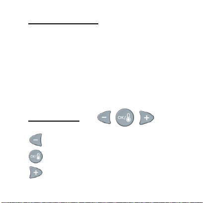
KEYBOARD
Navigation key left and minus key (-◄)
Validation key and mode key (OK)
Navigation key right and plus key (►+)
5
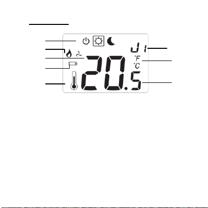
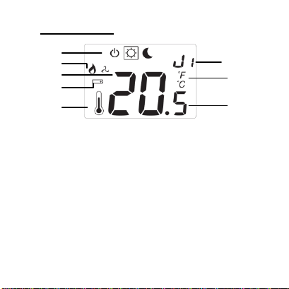
DISPLAY
1: Operating mode menu (active mode is framed).
2: Heating demand indication.
3: Cooling demand indication.
4: Batteries weak.
5: If lit-up “6” displays the measured temperature.
6: Measured temperature or setting temperature.
7: °C or °F indicator.
8: Moving bars when transmitting a radio signal
Or Title for installation Parameters (rF,
J0,CLr…)
8
7
6
1
2
3
4
5

6
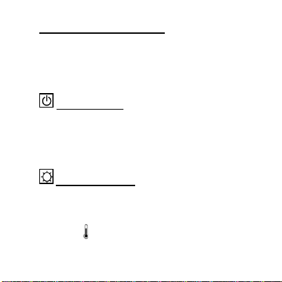
MODE DESCRIPTION
Use the (OK) key to change the mode in the
Operating mode menu. (The active mode is framed)
OFF mode:
Use this mode if the zone managed by the
thermostat needs to be turned OFF.
The display will be turned off and all parameters are
saved. (Careful in this mode your installation can
freeze).
COMFORT operating mode:
The comfort temperature will be followed all the
time. By pressing keys (-◄) or (►+) the comfort
temperature starts to blink and can be adjusted.
The measured temperature
reappears after a few
seconds.

7
REDUCED operating mode:
The comfort temperature will be followed all the
time. By pressing (-◄) or (►+) keys the comfort
temperature starts to blink and can be adjusted.
The measured temperature (OK) reappears after a
few seconds.
8
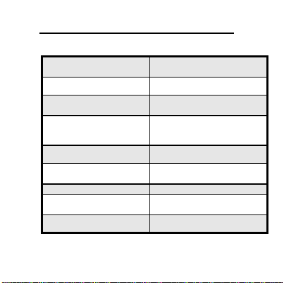
TECHNICAL CHARACTERISTICS
Measured temperature
precision
0.1°C
Operating temperature
0°C - 50°C
Setting temperature
range
5°C –37°C by 0.5°C step
Regulation
characteristics
Proportional Integral
regulation (PWM) (adjustable
see installation menu)
Electrical Protection
Class II - IP30
Power Supply
Battery operated life
2 x 3V (CR2430)
~ 2 years
Radio frequency
433.92 MHz, <10mW.
Certifications
EN 300220-1, -2
EN 301489-1, -3
Soft version
V 3.xx

9
INSTALLATION PARAMETERS MENU
Press the (OK) key during 5 seconds, then use (-◄)
or (►+) to select the installation parameter to be
adjusted.
Press (OK) to toggle the parameter setting or edit
the value.
If the value starts to blink you can use (-◄) or (►+)
keys to adjust this value.
Press (-◄) or (►+) keys at the same to reset this
value to the factory default value. Once you have
adjusted the value press (OK) to validate this
parameter value.
10
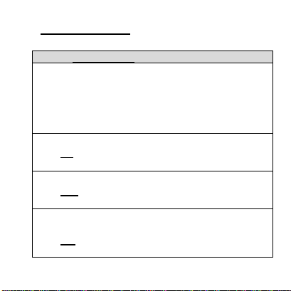
PARAMETERS
Default value & other possibilities
rF: Radio configuration mode (see the
corresponding section).
Press (OK) on this parameter to exit the
parameters menu end come back to the main
display.
JO: Type of degrees displayed
°CCelsius
°FFahrenheit
J1: Operating mode:
Hot for heating application
CLd for cooling application
CY: Proportional Integral regulation time cycle
value in minutes:
15 slow systems adapted to the regulation of
actuators.

11
Bp: Value of the proportional band in °C:
2.0 °CAdjustable 1°C to + 7°C
Increase the value if the temperature in the
room is unstable.
J5: Anti-lock-braking function of the pump when
the pump hasn’t worked on a particular day, start it
up for one minute each day:
Pmp Function activated
no Function deactivated
J6: Selection of the sensor used for the regulation:
Air:Room sensor only or room sensor with
floor limitation if the external sensor is
connected.
Flr: External sensor only without
limitations.

12
J7: Selection of regulation type:
rEg: Proportional band (PWM)
hys: Static differential of 0.3°K
Cp: Value of the compensation in °C:
2.0°CAdjustable 1°C to 8°C
* This value must be adjusted by a specialist.
A0: Calibration of the internal sensor
(The calibration must be done after 12Hours
working with the same setting temperature)
- To check the temperature in the room, put a
thermometer at 1.5M distance to the floor in the
concerned room and wait 1 hour to be sure that
the thermometer show the correct temperature.
Then you can enter the value saw on the
thermometer with (-◄) or (►+) keys.

13
F0: Calibration of the external sensor.
The calibration must be done same as described
above if the external sensor is connected and
used like an external ambiance sensor.
If the external sensor is used as floor sensor, the
thermometer should be put on the floor.
FL: Lower limitation of the floor temperature. Only
effective if the external sensor is connected and
selected:
5°CAdjustable From 5°C to „FH“
FH:Upper limitation of the floor temperature. Only
effective if the external sensor is connected and
selected:
28°CAdjustable From „Fl“ to 37°C
Clr: All parameters are reloaded with default
setting values.

14
„RF“ CONFIGURATION
- To assign (*) the RF thermostat with the UFH-
ZONEHC-R or the UFH-ZONE-R you must put
them in „RF init“ mode.
(Please refer to the receiver leaflet for this).
-After you have just pressed (OK) key during 5
sec, then the display „RF“ must be appears.
The thermostat sends its configuration address by
radio signal.
- Check the good reception on the UFH receiver.
When the receiver is configured, press the (OK) key
to return to the user menu.
* (In this mode, the thermostat should be near the
receiver)

15

16
PRESENTATION
- Thermostat Radio Fréquence (433,92 Mhz),
destiné à la régulation de plancher chauffant géré
par électrovannes.
- Possibilité de réguler sur :
oSonde ambiance seule
oSonde sol seule
oAmbiance et sonde de sol combinées.
Dans ce cas là la sonde de sol est
généralement utilisée en limitation.
CLAVIER
Navigation touche gauche et touche - (-◄)
Touche de validation et touche mode (OK)
Navigation touche droite et touche + (►+)
17
AFFICHEUR
1 : Mode de fonctionnement (mode activé encadré)
2 : Indicateur de chauffe
3 : Indicateur de refroidissement
4 : Témoin batteries faibles
5 : Si le symbole est présent, la température
ambiante est affichée en (6)
6 : Montre la température ambiante ou la consigne
7 : Température en °C ou °F
8 : Symbole de transmission RF ou titre des
paramètres d’installation (rF, J0, Clr…)
8
7
6
1
2
3
4
5
18
MODE DESCRIPTION
- Votre thermostat est équipé d’une touche (OK)
pour changer de mode de fonctionnement (le mode
actif est encadré):
Mode ARRET :
Utiliser ce mode si votre chauffage doit être coupé.
(Attention ce mode ne maintient pas une
température de Hors Gel). Les températures
réglées sont sauvegardées indéfiniment.
Mode CONFORT:
Le thermostat suit la température de confort
indéfiniment. Pour ajuster la température de confort
utiliser les touches (-◄) ou (►+). La température
ambiante
est de nouveau affichée après quelques
secondes.

19
Mode ECO (Réduit)
Le thermostat suit la température réduite
Indéfiniment. Pour ajuster la température de
confort utiliser les touches (-◄) ou (►+). La
température ambiante
est de nouveau affichée
au bout de quelques secondes.

20
CARACTERISTIQUES TECHNIQUES
Précision de mesure
0.1°C
Température de
fonctionnement
0°C - 50°C
Plage de réglage de la
température
5°C –37°C by 0.5°C step
Caractéristiques de
régulation
Bande proportionnelle
intégrale (Durée du cycle
ajustable voir paramètres
d’installation)
Protection
Class II - IP30
Alimentation
Autonomie
2 x 3V (CR2430)
~ 2 years
Fréquence radio
433.92 MHz, <10mW.
Homologations
EN 300220-1, -2
EN 301489-1, -3
Version du programme
V 3.xx
Other manuals for UFH-THERM-RD
1
Table of contents
Languages:
Other Henco Thermostat manuals


