TCW Technologies Integrated Back-up Battery System User manual
REV 1.6 © 2019 TCW Technologies, LLC.
1
Integrated Back-up Battery System
Model: IBBS-12v-6ah
The Integrated Back-up Battery System, IBBS,is an electronic system
that combines a Lithium-Iron-Phosphate (Li-Fe-PO4) battery pack, a
charger and switching logic in one convenient package. The IBBS
provides an engineered solution to enable an endurance bus for critical
loads found in aircraft. It simplifies the wiring and installation of a source
of back-up power by integrating all of the key elements into a single
enclosure. The IBBS system provides back-up power to critical
electronic loads such as EFIS, GPS, Autopilots and engine monitor
systems.
Integral to the IBBS is a lithium-iron-phosphate battery pack and a
matched charging system to ensure the battery is properly charged and
maintained. The system also includes switching circuitry to provide a
stable source of output power during normal and emergency operations.
The IBBS system also provides signals to other equipment such as EFIS
systems to communicate the operating state of the main aircraft bus as
well as the state of the battery.
The IBBS system connects to the standard aircraft power bus and
provides an output to critical equipment that require back-up power.
Additionally, the IBBS system provides surge and sag protection for
connected equipment, allowing operation of critical equipment during
engine starting.

REV 1.6 © 2019 TCW Technologies, LLC.
2
The IBBS system is suitable for use with equipment such as Garmin
GNS and GTN series navigators, G3X series of avionics, Grand Rapids
Technologies EFIS systems, Advanced Flight Systems EFIS, Dynon
EFIS, and MGL EFIS, TruTrak Autopilots and EFIS, Trio Autopilots.
No other uses of the IBBS system are permitted except for those
identified in this installation manual.
IBBS must be installed using the current aircraft standards and practices
as shown in AC 43.13-2A/1B. The installer/builder is solely responsible
for determining the suitability of the installation and use of this product.
IBBS products are protected by US Patent 8,189,305
Table of Contents
Installation Information: pg. 3
General Product info: pg. 5
Battery Capacity details: pg. 6
Product Operation: pg. 7
Requirements for Continued Airworthiness: pg. 8
Specifications pg. 11
Connector Pin-out pg. 12
Mounting plate drawing pg. 13
General Wiring diagram pg. 14
Example Wiring diagrams pg. 15-19
Warranty information pg. 20
Service and Support information:
610-928-3420 TCW Technologies, LLC.
www.tcwtech.com 2955 Main Road East

REV 1.6 © 2019 TCW Technologies, LLC.
3
Installation Instructions:
1. IMPORTANT NOTE:
Consult the attached wiring diagrams to identify wiring connections similar to your particular
installation. Please note, some equipment such as GPS’s and EFIS systems may be
provided with multiple power inputs. For these installations the output of the IBBS must be
connected to their “back-up” power input. The “back-up” power source should be provided
through the IBBS product. For equipment having a single source of power, the IBBS system
may be fed from a bus that remains active during engine starting, such as the master bus or
it may be fed from an avionics bus that is switched off during engine starting.
2. Check that the total connected load (summed value of all four output wires) is less
than the following product ratings:
IBBS-12v-6ah: 8 amps maximum continuous current
12 amps peak for radio transmissions and transient loads*
*(30 seconds max duration)
3. Mount the IBBS in a suitable location in the aircraft. Ensure the mounting points and
fasteners are suitable for the weight of the product, consult the specifications for details. The
IBBS must be mounted inside the aircraft, do not mount the IBBS in the firewall forward
area. Do not mount the IBBS unit up under the instrument panel unless the panel is
properly ventilated to ensure heat does not build up in the area. Select an area that is
accessible to allow for future battery servicing. The operating temperature range of the
system is -10 C° to 60 C°, the effective charging temperature range is 0 C° to 40 C°.
Select an installation location that will comply with these requirements.
4. Connect the aircraft wiring according to one of the wiring diagrams shown.
The IBBS must be powered through a properly sized circuit breaker or fuse. ENSURE the
proper size wire is utilized for the input feed, output supply and ground connection.
Power Input Requirements: The IBBS has multiple power inputs.
Pin 5 provides charging and bus voltage sensing for the IBBS unit and must be connected
to an aircraft power bus. When the voltage on pin 5 falls below about 11 volts the system
automatically transfers the load current on the output pins to the internal back-up battery
source. Pin 5 maximum current draw is 4.0 amps during charging.
Pins 6,7,8 receive power that is passed-thru the IBBS unit to the loads connected to the
output pins. These pass-thru power connections are optional and are only required for
systems that do not have multiple power inputs. These pins can also be used if it is desired
to have redundant power paths feeding the connected loads. These pins are internally
wired in parallel, it is recommended to populate all three pins and join the wires together at
the pass thru power breaker. Note: these pins do not individually correspond to any
particular output pin (12-15). The pass-thru breaker must be sized for whatever load is
connected to the IBBS outputs. The maximum combined load is 12 amps peak, 8 amps
continuous. If Pins 6,7,8 are used they MUST be connected to the same power bus as Pin
5.

REV 1.6 © 2019 TCW Technologies, LLC.
4
Output Power connections:
The IBBS-12v-6ah has four output pins, Pins 12,13,14,15. These pins provide power to the
connected load. These four wires may be paralleled together for redundancy and load
current sharing. Use 20 awg wire for each pin. Maximum output current of 3.5 amps per
pin, and 8 amps maximum continuous combined for all four pins. The output wires of the
IBBS system are protected with a single 10 amp, mini ATC fuse. This fuse is accessible on
the side of the enclosure.
IMPORTANT NOTE ON CHANGING FUSE:
Disconnect the main product connector before changing the fuse!
Replace fuse with 10 amp, mini ATC fuse only
5. The Back-up Power Master switch must be utilized to turn the back-up battery system
off when not in use, except for installations where the off state current requirement is less
than 50 micro-amps, such as with the AFS EFIS systems. Follow the specific wiring
diagram for this application. This back-up power master switch gives the pilot the ability to
turn the back-up battery system off. In some installations this may be the only means to
shut down the connected equipment.
6. The IBBS unit has a low voltage warning output, pin 3. This pin may be used to drive
an LED indicator or to provide a digital signal to indicate the main input bus is in a low
voltage condition. When the main input bus (connected to pin 5) falls below about 11 volts
this output will drive to a low state. Maximum current sourced on this pin is 25 milliamps.
7. The IBBS unit has in internal battery monitor connection, pin 2. This pin allows the
voltage state of the internal battery to be monitored with a separate voltage meter or analog
input. This pin will only report internal battery voltage when the unit is enabled by turning
the Back-up Master switch ON. A fully charged battery back will indicate about 13-14.7 volts
on this pin. Important note: the meter utilized to measure pin 2 must have an input
impedance >100k ohms otherwise it will load down pin 2 and provide an artificially
low voltage.
8. Complete the installation of the wiring harness and connector prior to attaching the
connector to the IBBS product. This is essential to ensure the wires do not inadvertently
short together during installation. Remember, the IBBS pack is a back-up source of power
and is ready to deliver output power even when the aircraft electrical system is in the off
state.
9. When using the IBBS product to provide back-up power to an electronic ignition
system it MUST be used to back-up one and only one electronic ignition module. Do not
use one IBBS to back up both electronic ignition modules in a dual electronic ignition
system. Follow the wiring diagram for installation with electronic ignition module. Note, the
Light Speed Electronic ignition system connects directly to aircraft battery as shown. Other
brands of electronic ignition systems connect to the switch side of the aircraft master bus.
Follow the instructions per the electronic ignition manufacture for your installation.

REV 1.6 © 2019 TCW Technologies, LLC.
5
10. When using the IBBS product to provide back-up power to an electronic ignition
system (CDI), pull-able circuit breakers must be used for over current protection as shown
on page 18.
11. When using the IBBS product to provide back-up power to an electronic ignition
system, connect one and only one CDI module to an IBBS unit. DO NOT CONNECT
any other loads to the IBBS. It must only be used to back up the CDI unit.
Product Details and General Information:
The Charging System:
The IBBS automatically maintains its internal battery pack. The internal charging circuit
monitors the state of the internal battery and recharges it as necessary when the aircraft is
operational. The maximum input current for battery recharging is 4.0 amps.
If the internal battery is fully discharged for any reason it may require up to two hours of
recharge time with the normal aircraft bus on. NOTE: Do not attempt to recharge the IBBS
product by using an external battery charger directly connected to the input of the IBBS.
Battery chargers typically provide pulsating voltages that may damage the IBBS product if
the system is not connected to a typical primary aircraft battery.
Back-up Power Master Switch:
The IBBS has one input switch connection as identified in the wiring diagrams: Back-up
Power Master. This switch enables back-up power from the IBBS system to be available on
the output wires when power on the normal aircraft bus falls into the range of 10-11 volts.
If the back-up power master switch is enabled and normal aircraft power falls into the range
of 10-11 volts, then the internal back-up battery will be connected to the outputs and be
utilized to supply back-up power to the connected load.
If the normal aircraft power bus is above 11 volts, then the outputs are energized with normal
aircraft power (if the pass thru-power connections are utilized) and the back-up battery
remains off-line. This operation occurs regardless of the state of the Back-up Power Master
switch. This allows for automatic pass through of power during normal operation.
Ground Based Recharging:
To accomplish ground based charging, connect an approved battery charger or DC power
source to the main aircraft battery and energize the main aircraft power bus by turning on the
master switch, leave all other aircraft loads in their off state. Note, the ground base source
of power must be able to supply the load current of all devices that can not be turned off in
this nominal state, plus the 4.0 amps of IBBS recharge current. Leave the ground based
charging system connected and powered until the IBBS system completes its recharge cycle
of its internal battery, for a fully discharged battery this may take up to two hours.
Alternately, a ground based charger is available from TCW Technologies LLC., model #
IBBS-12v-CHARGER-LI-FE. This charger may be used for recharging the IBBS unit as
well as keeping it topped off during long term product storage. (9 months or longer)

REV 1.6 © 2019 TCW Technologies, LLC.
6
Battery Capacity:
The IBBS provides an energy capacity of 6 amp-hours at 12.8 volts when the system is fully
charged and operated at 25 C°. Depending on various conditions including operating and
storage temperature and age of the battery pack, the capacity of the system will vary. With a
fully charged battery, the following average performance can be expected in terms of
operating duration. The operating duration is for output voltage down to 10.0 volts.
Nominal Current Draw Duration
total connected load
1.5 amps 240 minutes
3.0 amps 110 minutes
6.0 amps 55 minutes
The internal battery in the IBBS system is replaceable, however, the IBBS product must be
returned to TCW Technologies, LLC. for this service. Battery life depends strongly on many
factors including operating and storage temperature, number of discharge cycles and depth
of discharge. The battery capacity should be checked at least annually for suitable back-up
power operation of the connected equipment. When the battery capacity no longer meets
the operating criteria of the aircraft it must be replaced. Contact TCW Technologies, LLC.
for battery replacement.
Storage beyond 9 months:
If the IBBS unit is to be stored without connection to the aircraft for a period greater than 9
months it must be connected to a source of DC power to maintain the battery’s charge. Only
connections to the ground terminal and the main power terminal are required. Connect Pin
5 (main power) and Pin 9 (ground) of the IBBS to any source of regulated DC power at 12-15
volts with a current capability of > 4.0 amps to accomplish full recharging. Charger model
IBBS-12v-CHARGER-Li-Fe is available from TCW Technologies, LLC. to simplify this
requirement, it has the mating connector installed.
Upon completion of installation:
1) The builder/operator is responsible for determining the minimum operating duration of the
back-up enabled equipment.
2) The required back-up operating time for the connected equipment should be recorded in
the aircraft log-book with follow-up entries confirming the annual testing results that
indicate that the required operating time is satisfied.

REV 1.6 © 2019 TCW Technologies, LLC.
7
Normal Product Operation:
For normal operation the following is the recommend operating procedure, it is strongly
recommended that this operating procedure be added to the aircraft operating check-list for
standard procedures.
Start-up Procedure:
1) Prior to turning on the Aircraft Master Switch, turn ON the Back-up Power master switch.
2) Turn on any equipment that derives back-up power from the IBBS product.
3) Ensure the connected equipment successfully boots-up and is operating properly. (During
this period of time the equipment is running off of the back-up battery in the IBBS product.
This test ensures the transfer circuit and back-up battery are properly working)
4) Turn on the Aircraft Master Switch; ensure the connected equipment remains energized.
(If you are utilizing a separate avionics bus, this may need to be turned ON to continue the operation
equipment connected to the IBBS output.)
5) Start and operate the aircraft according to normal operating procedures.
Shut-down Procedure:
1) Shut down aircraft engine using normal procedures.
2) Shut down the Aircraft Master Switch
3) Verify that equipment that derives back-up power from the IBBS product remains ON
4) Turn-off Back-up Power Master switch, ensure that equipment powers down.
(This procedure further ensures the operation of the transfer circuit in the IBBS product.)
Emergency Procedure for loss of main aircraft electrical power:
1) Operate the Aircraft Master Power Switch per the Emergency Procedure checklist already
established for the aircraft.
2) Ensure the Back-up Master Switch is in the ON position.
3) Land aircraft as soon as practical to resolve the loss of main electrical power.

REV 1.6 © 2019 TCW Technologies, LLC.
8
Requirements for continued airworthiness:
On at least an annual basis the endurance capability of the IBBS system shall be confirmed and compared
against the back-up endurance required for the connected equipment.
As an alternate to these tests, the IBBS unit may be returned to TCW Technologies for a
loaded endurance test, contact TCW Technologies LLC. for details.
Procedure for endurance testing
All applications except electronic ignition systems
1) Turn off the Aircraft Master Switch
2) Turn on the Back-up Power Master Switch
3) Turn on all equipment connected to and supplied with back-up power from the IBBS
product.
4) Measure and record at least the following information: The time until the first piece of
connected equipment no longer functions or the time until the output of back-up power
supply voltage drops to 9.5 volts. AVOID allowing the back-up battery voltage to fall
below 9 volts.
5) After completing the endurance test, recharge the IBBS product by operating the system
with the Aircraft Master Switch in the ON position for up to two hours. This may done by
operating the aircraft in conditions known to not require back-up power or by powering the
aircraft system on a suitable ground power source as described in the section: Ground
Base Recharging.
6) Record the results of the endurance testing in the aircraft log book.
7) If the IBBS no longer meets the endurance testing requirement, the back-up battery may
need replacement.

REV 1.6 © 2019 TCW Technologies, LLC.
9
Requirements for continued airworthiness:
Electronic Ignition System Back-up
On at least an annual basis the endurance capability of the IBBS system shall be confirmed and compared
against the back-up endurance required for the connected equipment.
As an alternate to these tests the IBBS unit may be returned to TCW Technologies for a
loaded endurance test, contact TCW for details.
Procedure for endurance testing of system providing back-up power
to electronic ignition systems:
COMPLETE THESE STEPS IN ORDER! Perform these tests with the aircraft properly
secured on the ground, these are not flight test procedures.
1) Start the aircraft using normal starting procedures, including turning ON the Back-up
Master switch
2) Select engine operation based on the use of only the electronic ignition module provided
with back-up battery power.
3) PULL the 5 amp breaker feeding the Back-up Master Switch, confirm engine continues to
run.
4) PULL the 7.5 amp breaker feeding pins 6,7,8 of the IBBS, confirm the engine continues to
run.
5) Perform the following; test A or test B:
Test A: abbreviated battery test:
Monitor engine operation and voltmeter reading on any of pin 12,13,14,15, the back-up
power output. Confirm back-up voltage begins above 12.0 volts and for a period of 15
minutes remains above 11.0 volts. If these requirements are met the battery pack is
satisfactory.
Test B: full endurance test:
Operate the engine on the electronic ignition system for the required minimum run-time
requirement (typically 60 minutes ) monitor the back-up battery voltage on the voltmeter
connected to an output pin, the battery voltage must remain above 10 volts for the
duration of the test. If this requirement is met the battery pack is satisfactory.
6) Turn off the Back-up Master Switch and confirm that the engine turns off.

REV 1.6 © 2019 TCW Technologies, LLC.
10
7) IF all these tests pass, the IBBS system is functioning properly, record the results in the
aircraft log book.
8) IF any of these tests fail, the IBBS system is not functioning properly and corrective action
must take place. If the IBBS no longer meets the endurance testing requirement, the
back-up battery may need replacement.
9) Return all pullable breakers to the normal ON position and ensure aircraft engine is
properly returned to the off position by following normal run and shut down procedures.
10)After completing these tests, recharge the IBBS product by operating the system normally
for up to two hours. This may done by operating the aircraft in conditions known to not
require back-up power or by powering the aircraft system on a suitable ground power
source as described in the section: Ground Base Recharging.

REV 1.6 © 2019 TCW Technologies, LLC.
11
SPECIFICATIONS:
Input Voltage:* 13-15 volts DC
Transition Voltage: ** 10.5-11.5 volts
Input Current: 4.0 amps max continuous on main input for charging
Pass-thru Current: 8 amps continuous, 12 amps peak (30 seconds)
Output Voltage: 10-14 volts DC during back-up operation
Output Current: 8 amps continuous
12 amps peak for radio transmissions and transient
load (30 second duration max)
Battery: Internal sealed Li-Fe-PO4
Charger: Integral high performance fast charger
Surge Protection: 34 volt active clamp, 1500w 10/1000uS waveform
Wiring: 15 pin male D-sub on product.
Enclosure: Aluminum 7.7” x 2.3” x 2.65”
Weight: 34 oz.
Temperature range: Operating -10 C° to 60 C°
Charging 0 C° to 40 C°
Connector: Standard density 15 pin male D-sub on product
*Minimum input voltage for battery recharging.
**Transition voltage is the voltage level on the input that causes the system to provide output power via the internal
back-up battery

REV 1.6 © 2019 TCW Technologies, LLC.
12
Wiring connector detail:
Male on IBBS unit
Female on aircraft wiring harness
View from back of connector on harness
Pin # Function
5 PWR + in, charge, sensing
2 Batt-info
3 Low Volt Warn
12 Output
13 Output
14 Output
15 Output
6 Pwr +, pass-thru input
1 Enable- backup switch
9 Ground
10 Ground
11 Ground
15 pin Male Dsub on unit
7 Pwr +, pass-thru input
8 Pwr +, pass-thru input
4 N/C

REV 1.6 © 2019 TCW Technologies, LLC.
13
Product mounting footprint
4 mounting holes. 0.190
1.50
7.25
2.290
7.70
Top View
0.225
Product height 2.75”

REV 1.6 © 2019 TCW Technologies, LLC.
14
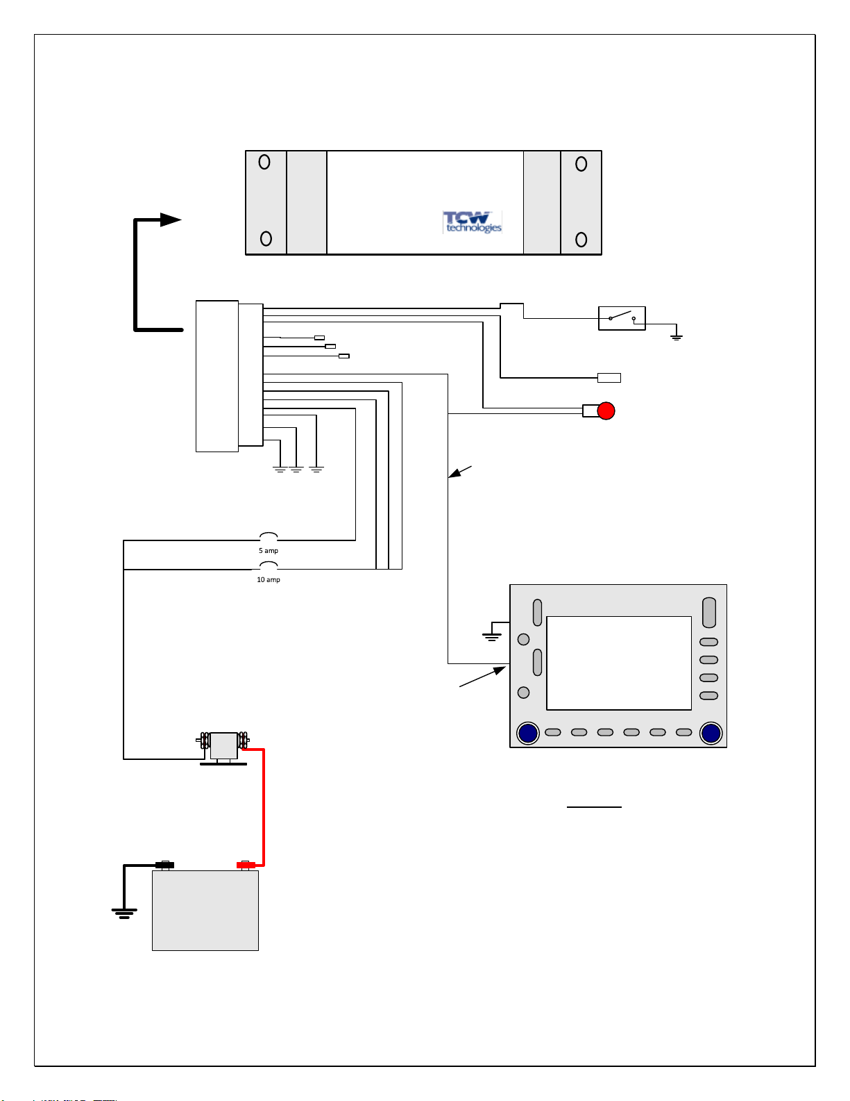
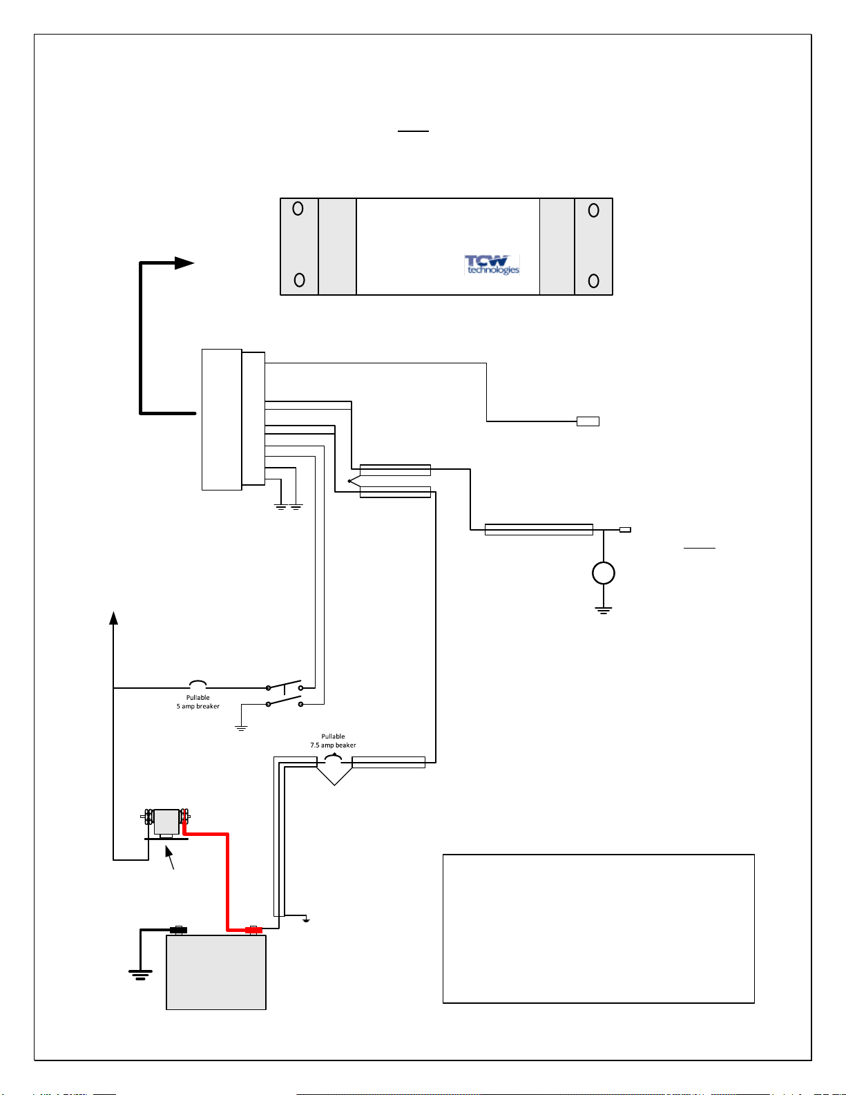
General Wiring Diagram
5 amp
Main Aircraft Bus
Back-up Power Master
15 pin, female
Dsub connector
Back-up power output
Total combined load on all outputs = 8 amps
Batt-info to volt meter
Back-up power output
Back-up power output
20 awg
20 awg
20 awg
Back-up power output
20 awg
10 amp
Main Aircraft Bus
charge/sense
pass-thru
Pin # Function
15 pin Male Dsub on unit
12 Output
13 Output
14 Output
15 Output
9 Ground
10 Ground
11 Ground
5 PWR + in, charge, sensing
2 Batt-info
3 Low Volt Warn
6 Pwr +, pass-thru input
1 Back-up master switch
7 Pwr +, pass-thru input
8 Pwr +, pass-thru input
4 n/c
Pin # Function
+
-Low Voltage Warning LED,
25 mA max
www.tcwtech.com
Emmaus, PA USA
MODEL: IBBS-12V-6AH
Input: 10-15 volts DC
Output: 12 volts,8 amps
INTEGRATED
Back-up Battery
SYSTEM
REV 1.6 © 2019 TCW Technologies, LLC.
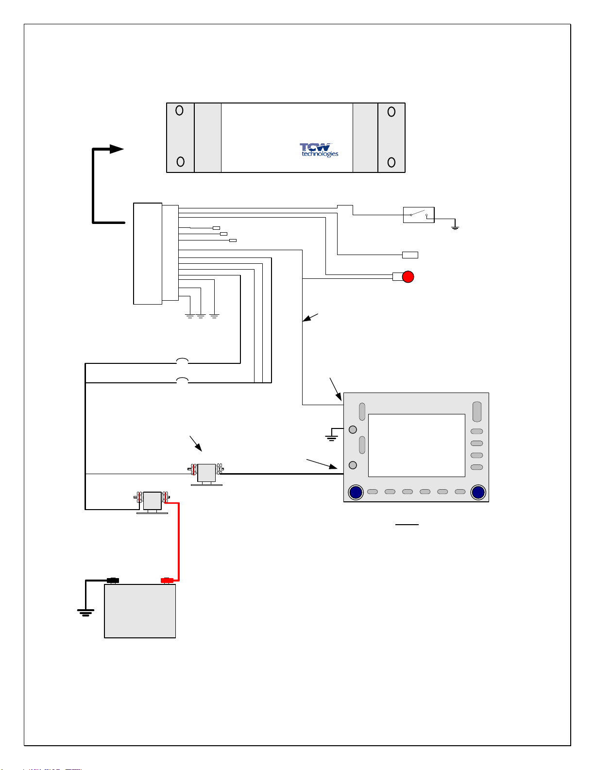
15
Battery
Master Solenoid
Wiring Diagram IBBS-12v-6ah
Equipment being
powered via IBBS
Example wiring for systems without back-up power inputs,
including Electronic Ignition systems other than LSE brand.
Equipment without Back-up Power Input
Main Aircraft Bus
Back-up Power Master
Battery-Info
Back-up power output
20 awg
22 awg
22 awg
20 awg
20 awg
20 awg
1
6
9
10
2
5
12
main power input
15 pin, female
Dsub connector
3
+
-Low Voltage Warning LED
NOTE: Use redundant ground pins 9,10,11
Use redundant power inputs 6,7,8
based on load current of connected
equipment
7
11
8
13
14
15 output
output
output
www.tcwtech.com
Emmaus, PA U SA
MODEL: IBBS-12V-6AH
Input: 10-15 volts DC
Output: 12 volts,8 amps
INTEGRATED
Back-up Battery
SYSTEM
REV 1.6 © 2019 TCW Technologies, LLC.
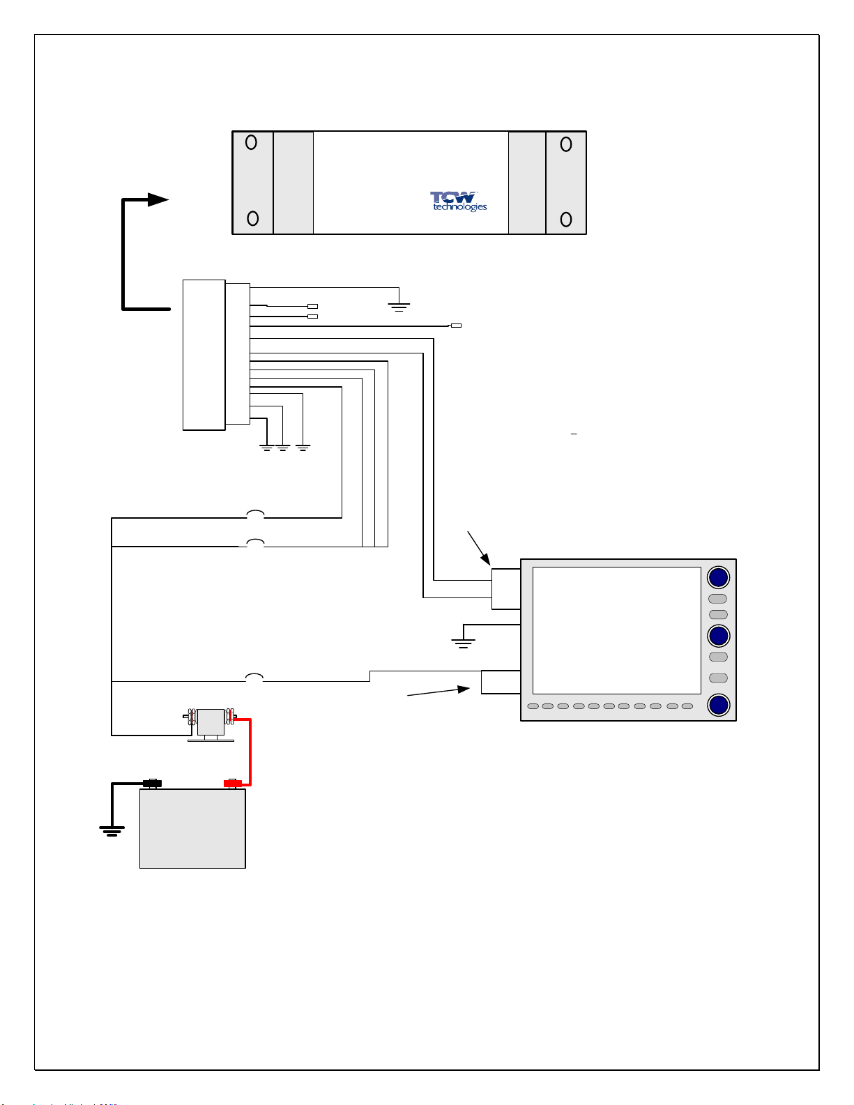
16
Avionics Bus Solenoid
Avionics Bus
Battery
Master Solenoid
Wiring Diagram IBBS-12v-6ah
Equipment being
powered via IBBS
Example wiring for systems with back-up power inputs
Equipment with Back-up Power Input
5 amp
Main Aircraft Bus
Back-up Power Master
Battery-Info
Back-up power output
20 awg
22 awg
22 awg
20 awg
20 awg
20 awg
1
6
9
10
2
5
12
Main power input
15 pin, female
Dsub connector
3
+
-Low Voltage Warning LED
NOTES:
7
11
10 amp
8
13
14
15 output
output
output
www.tcwtech.com
Emmaus, PA USA
MODEL: IBBS-12V-6AH
Input: 10-15 volts DC
Output: 12 volts,8 amps
INTEGRATED
Back-up Battery
SYSTEM
Back-up power input
3) Use of power pins will power connected equipment even when avionics
bus is OFF via pass thru mode. Use of input pins 6,7,8 is OPTIONAL.
2) Use redundant power inputs 6,7,8 based on load
current of connected equipment.
1) Use redundant ground pins 9,10,11

REV 1.6 © 2019 TCW Technologies, LLC.
17
Battery
Master Solenoid
Wiring Diagram IBBS-12v-6ah
IBBS with Garmin G3x
5 amp
Main Aircraft Bus
Back-up Power Master
20 awg
20 awg
1
6
9
10
2
5
15 pin, female
Dsub connector
NOTES:
7
11
10 amp
8
13
14
15
www.tcwtech.com
Emmaus, PA USA
MODEL: IBBS-12V-6AH
Input: 10-15 volts DC
Output: 12 volts,8 amps
INTEGRATED
Back-up Battery
SYSTEM
1) Use redundant ground pins 9,10,11
2) See Garmin install manual for all wiring details and fusing requirements
Garmin G3x Avionics
GDU 46x
or
GDU 37x
Pin 31
J3701
Pin 32
Primary power connections for G3x system
power connections for G3X system
GSU 25
J251
Pin 7
Pin 8
GEA 24
Pin 8
J241
Pin 7
J244
Pin 28
GAD 29
Pin 8
Pin 7
J291
GDU 46x
or
GDU 37x
Pin 31
J3701
Pin 32
3) Enable Volts2 display in Garmin Set-up Software to display IBBS battery voltage
REV 1.6 © 2019 TCW Technologies, LLC.
18
Expansion connector
Back-up pwr input pin 6
Volts2 input pin 13
Advanced Flight
Systems
5000 series
main power input on
main connector
pin1
pin 15
pin6
Battery
Master Solenoid
Wiring Diagram IBBS-12v-6ah
Wiring Advanced Flight Systems 5000 series
5 amp
Main Aircraft Bus
20 awg
22 awg
20 awg
20 awg
1
6
9
10
2
5
12
15 pin, female
Dsub connector
NOTES:
7
11
10 amp
8
13
14
15 output
Output, to additional AFS efis
www.tcwtech.com
Emmaus, PA USA
MODEL: IBBS-12V-6AH
Input: 10-15 volts DC
Output: 12 volts,8 amps
INTEGRATED
Back-up Battery
SYSTEM
2) Use redundant power inputs 6,7,8 based on load current of connected equipment.
1) Use redundant ground pins 9,10,11
3) No back-up master switch required when wired per this drawing for AFS 5000 series.
5 amp
output
pin13
4) Enable Volts2 display in AFS setup screen to display IBBS battery voltage
REV 1.6 © 2019 TCW Technologies, LLC.
19
Battery
Master Solenoid
Main Aircraft Bus
20 awg Shielded OUTPUT
Power for
ONE
Electronic Ignition module
shields tied together
shields tied together
shield tied to
battery ground
20 awg Shielded
Back-up of ONE CDI in a single or dual CDI
installation. Use with LSE Plasma II and III
electronic ignition
Back-up power
master switch
Wiring diagram for use with electronic ignition such as
LSE Plasma II and III
Consult ignition module wiring documents for specific
wiring requirements.
Do Not use the Low Voltage Warning LED with this
application
Note:
V
recommended
volt meter location
Wiring Diagram IBBS-12v-6ah
Battery-Info
22 awg
1
6
9
10
2
5
12
15 pin, female
Dsub connector
3
7
13
14
15
www.tcwtech.com
Emmaus, PA U SA
MODEL: IBBS-12V-6AH
Input: 10-15 volts DC
Output: 12 volts,8 amps
INTEGRATED
Back-up Battery
SYSTEM

REV 1.6 © 2019 TCW Technologies, LLC.
20
TCW Technologies, LLC.
During the first 12 months from the date of purchase and subject to the conditions hereinafter set forth, TCW Technologies,
LLC. (TCW) will repair or replace to the original user or consumer any portion of your new TCW product which proves
defective due to defective materials or workmanship of TCW. Contact TCW Technologies for warranty service. TCW shall
have and possess the sole right and option to determine whether to repair or replace defective equipment, parts or components.
Damage due to equipment, environment or conditions beyond the control of TCW Technologies are NOT COVERED BY
THIS WARRANTY.
LABOR, COSTS: TCW shall IN NO EVENT be responsible or liable for the cost of field labor or other charges incurred by
any customer in removing and/or reaffixing any TCW product, part or component thereof.
THIS WARRANTY WILL NOT APPLY: (a) to defects or malfunctions resulting from failure to properly install, operate or
maintain the unit in accordance with printed instructions provided; (b) to failures resulting from abuse, accident, or negligence;
(c) to normal maintenance services and the parts used in connection with such service; (d) to units which are not installed in
accordance good trade practices; or (e) to unit used for purposes other than for what it was designed and manufactured.
RETURN OR REPLACED COMPONENTS: any item to be replaced under this Warranty must be returned to TCW
Technologies in Emmaus, PA, or such place as TCW may designate, freight prepaid.
PRODUCT IMPROVEMENTS: TCW reserves the right to change or improve its products or any portions thereof
without being obligated to provide such a change or improvement for units sold and /or shipped prior to such
change or improvement.
WARRANTY EXCLUSIONS: as to any specific TCW product, after the expiration of the time period of the warranty
applicable thereto as set forth above. THERE WILL BE NO WARRANTIES, INCLUDING ANY IMPLIED
WARRANTIES OR MERCHANTABILITY OR FITNESS FOR ANY PARTICULAR PURPOSE.
Some states do not allow limitations on how long an implied warranty lasts, so the above limitation may not apply to
you. No warranties or representations at any time made by any representative of TCW shall vary or expand the
provisions hereof.
LIABILITY LIMITATION: IN NO EVENT SHALL TCW OR ITS AFFILIATES BE LIABLE OR RESPONSIBLE FOR
CONSEQUENTIAL, INCIDENTAL OR SPECIAL DAMAGES RESULTING FROM OR RELATED IN ANY MANNER
TO ANY TCW PRODUCT OR PARTS THEREOF. THE SUITABILITY OF USE OF THE TCW TECHNOLGIES,
LLC. PRODUCT IS TO BE DETERMINED BY THE AIRCRAFT BUILDER.
Some states do not allow the exclusion or limitation of incidental or consequential damages, so the above limitation
or exclusion may not apply to you.
This Warranty gives you specific legal rights and you may also have other rights which vary from state to state. In
the absence of other suitable proof of this installation date, the effective date of this Warranty will be based upon the
date of manufacture plus one year. Direct All Notices To: Warranty and Product Service Department, TCW
Technologies, 2955 Main Road East. Emmaus, PA 18049
This manual suits for next models
1
Popular UPS manuals by other brands

Eaton
Eaton Powerware 9135 user guide

Powerware
Powerware Prestige 6000 Installation and operator's manual

GE
GE Lanpro 33 Installation and commissioning guide

Middle Atlantic Products
Middle Atlantic Products UPS-S1500R user manual

Chloride
Chloride Desk POWER 300 operating manual

PowerShield
PowerShield Centurion 10000 VA user manual


