Sola 610 User manual

AbpCompany
The Answer in Power Protection
SOLA 610
6&10kVA
50/60HzSingle Phase
UninterruptiblePowerSystem
Installationand
OperationManual
Savetheseinstructions!
This manual contains important instructions that should
be followed during installation and maintenance of the UPS.
Conservercesinstructions!
Cette notice contient des instructions importantes
concernant la securite!
Ref: 610MAN6K10K
Rev 2 Issued: September 97

This page intentionally left blank.

SOLA 610 UPS General Information
1.1 Table of Contents
i
Page Number
1. General Information
1.1 Table of Contents ..................................................................... i
1.2 Notice to UPS owners............................................................... ii
1.3 Preface..................................................................................... iii
1.4 FCC & Dept. of Communications Notice.................................... iv
1.5 Safety Notice and Warnings ...................................................... v
2. Installation
2.1 Introduction and product description.......................................... 1
2.2 Sizing the load .......................................................................... 1
2.3 Types of loads .......................................................................... 2
2.4 Laser Printers and your UPS..................................................... 2
2.5 Unpacking your UPS ................................................................ 2
2.6 UPS locations ........................................................................... 3
2.7 Recharging the UPS battery...................................................... 4
2.8 External Battery connection ...................................................... 4
2.9 Inverter Shutdown Link Installation ............................................ 5
2.10 Setting up the UPS monitoring from your computer ................... 6
3. UPS Operation
3.1 Switching on the UPS ............................................................... 8
3.2 When the power fails ................................................................ 8
3.3 When the power returns............................................................ 9
3.4 Front panel indicators ............................................................... 9
4. Optional Features
4.1 External Battery Options ........................................................... 10
4.2 Installing the CheckUPS II®software ......................................... 11
4.3 Operating CheckUPS II® .......................................................... 13
4.4 Installation and Operation of the AS400® card option ................ 26
4.5 Installation and operation of the SNMP Card option ................... 27
5. Maintenance and Warranty
5.1 Storage .................................................................................... 28
5.2 Maintenance and Cleaning........................................................ 28
5.3 Trouble shooting ....................................................................... 29
5.4 Model specifications ................................................................. 30
5.5 Warranty .................................................................................. 32
5.6 Serviceinstruction andservicelocations ................................... 33

SOLA 610 UPS General Information
1.2 Notice to UPS Owners
ii
Thank you for choosing a SOLA product, your answer in power
protection. Over many years SOLA has built a reputation by
designing and manufacturing top quality, reliable power quality
products. Your SOLA unit is designed for trouble-free operation
in a normal commercial environment.
In the unlikely event that your SOLA does need repair, please
refer to Section 5.6 of this manual. Should you wish to upgrade
the service guarantee to the premier FASTFIX exchange
service, or extend your warranty beyond the initial two years,
please contact your local SOLA office.
We encourage you to read this manual carefully in order to get
full benefit from the features built into your SOLA product. It is
recommended that you register your purchase by completing
the warranty registration card.
WARNING!
This unit has an internal battery
and is capable of generating
dangerous voltages. Do not open
the unit by removing the outer
case. Please read the SAFETY
WARNINGS on pages v and vi.

SOLA 610 UPS General Information
1.3 Preface
SOLA makes no warranty of any kind with regard to this
document, including, but not limited to, the implied warranties of
merchantability and fitness for a particular purpose. SOLA shall
not be liable for errors contained herein or for incidental or
consequential damages in connection with the furnishing,
performance, or use of this material.
This document contains proprietary information which is
protected by copyright. All rights are reserved. No part of this
document may be photographed, reproduced or translated to
another language without the prior written consent of SOLA.
This manual contains technical information about the following
SOLA UPS systems:
iii
Rating
kVA Model No. Part. No. Input/Output
Voltage Frequency
(autoselecting) Connection
60610-6000A S610-6000-A-000-00 240V 50/60 Hz Hardwired
10 0610-010KA S610-010K-A-000-00 240V 50/60 Hz Hardwired

SOLA 610 UPS General Information
1.4 FCC&Department ofCommunicationsNotice
iv
FCC NOTICE
This equipment generates and uses radio frequency energy; and, if installed in a residential
environment, may cause interference to radio and television reception. It has been type tested
and found to comply with the limits for a Class A/B* digital device, pursuant to part 15 of the
FCC rules. These limits provide reasonable protection against harmful interference when the
equipment is operated in a commercial environment. This equipment generates, uses and can
radiate radio frequency energy and, if not installed and used in accordance with the instruction
manual, may cause harmful interference to radio communications. Should the unit be installed
in a residential environment, it is the user's responsibility to remedy potential television and/or
radio interference. The following FCC booklet may be helpful in resolving interference:
How to Identify and Resolve Radio-TV Interference Problems (Stock Number 004-00-
00345-4)
This booklet is available from the U.S. Government Printing Office, Washington, DC 20402.
DEPARTMENT OF COMMUNICATIONS NOTICE
This digital apparatus does not exceed the Class A/B* limits for radio noise emissions from
digital apparatus as set out in the Radio Interference Regulations of the Canadian Department
of Communication.
AVIS DU MINISTERE DES COMMUNICATIONS
Les emissions de bruit radioelectrique produites par ce dispositif numerique respectant les
normes de Classe A/B* afferentes aux dispositifs numeriques enoncees dans le Reglement
relatif au brouiliage radioelectrique du Ministere Canadien des Communications.
The products meet the above as follows:
1. 6 & 10kVA 230V version.
2. Requirements for fixation of C-Tick 240V logo in Australia.

SOLA 610 UPS General Information
1.5 SafetyNoticeand Warnings
Important! Please read this before installing your UPS.
Warnings, Cautions and Notes appear throughout this manual. Please familiarise yourself with them
as they are essential for your safety and will enable you to maximise longevity of your UPS.
!
?
WARNING
Denotes a procedure or practice, which, if not performed correctly or adhered to,
may result in personal injury. Do not proceed beyond a Warning sign until the
indicated conditions are fully understood and met.
CAUTION
Denotes a procedure or practice, which, if not performed correctly or adhered to,
may result in damage to equipment. Do not proceed beyond a Caution sign until
the indicated conditions are fully understood and met.
Note
Denotes an essential procedure or practice.
v
SafetyWarnings
1. SERIOUS INJURY CAN OCCUR IF THE UNIT ENCLOSURE IS OPENED BY
UNQUALIFIED PERSONNEL. THERE ARE NO USER-SERVICEABLE PARTS
INSIDE THE UPS.
2. This unit is capable of supplying AC voltage even if there is no input present. Although
the System On/Off Switch on the front of the UPS is protected from accidental
actuation, be careful the unit does not become unintentionally enabled.
3. The SOLA 610 is not authorised for use as a critical component in life support devices
without the express written approval of the President of Best Power, as used herein:
a. Life support devices are devices or systems which sustain life, and whose failure
to perform can be reasonably expected to result in a significant injury to the
user.
b. A critical component is any component of a life support device or system whose
failure to perform can be reasonably expected to cause the failure of life support
or the system, or to affect its safety or effectiveness.
4. The SOLA 610 is a physically small package. Do not install the unit in a high traffic
area where people could trip on the unit, or its cables or cords.
5. Do not place objects or stack other equipment on top of the unit.

SOLA 610 UPS General Information
1.5 SafetyNotices andWarnings(cont.)
vi
Safety Warnings (cont.)
6. The SOLA 610 is intended for indoor use only.
7. Do not install the unit next to open windows where uncontrolled environmental
conditions could affect the unit.
8. Avoid plugging the unit into a wall outlet controlled by a switch. If the outlet is
controlled by a switch, cover or protect the switch from being accidentally turned
off. The wall switch will not turn off the UPS; instead the UPS may draw energy
from its battery and continue to supply output voltage. This may result in a loss
of backup protection until the battery is recharged.
9. A BATTERY CAN PRESENT A RISK OF ELECTRICAL SHOCK AND/OR
BURN FROM HIGH SHORT-CIRCUIT CURRENT. OBSERVE PROPER
PRECAUTIONS.
UNE BATTERIE PEUT PRÉSENTER UN RISQUE DE CHOC ÉLECTRIQUE,
DE BRÛLURE PAR TRANSFER D'ÉNERGIE. SUIVRE LES PRÉCAUTIONS
QUI S'IMPOSENT.
10. PROPER DISPOSAL OF BATTERIES IS REQUIRED. REFER TO YOUR
LOCAL CODES FOR DISPOSAL REQUIREMENTS.
L'ÉLIMINATION DES BATTERIES EST RÈGLEMENTÉE. CONSULTER LES
CODE LOCAUX À CET EFFET.
11. The input cord is the main disconnect.
Der Netzkabel is der Netztrennung.
12. The unit must be installed near the equipment to be powered and the socket-
outlet must be easily accessible.
Die Steckdose soll nahe des Geraetes eingebaut werden und leichter Zugang
haben.
13. No user-serviceable parts inside.
Kein gebrauche Zugang noetig.
14. Battery replacement by qualified service personnel only.
Batterieaustauch nur vom qualifizierten Wartungspersonal durchgefuehrt
werden.

SOLA 610 UPS Installation
Electrical equipment is often rated in VA (volt-amps). This
represents the rated voltage times the rated current, i.e. 230
Volts x 2 Amp = 460VA.
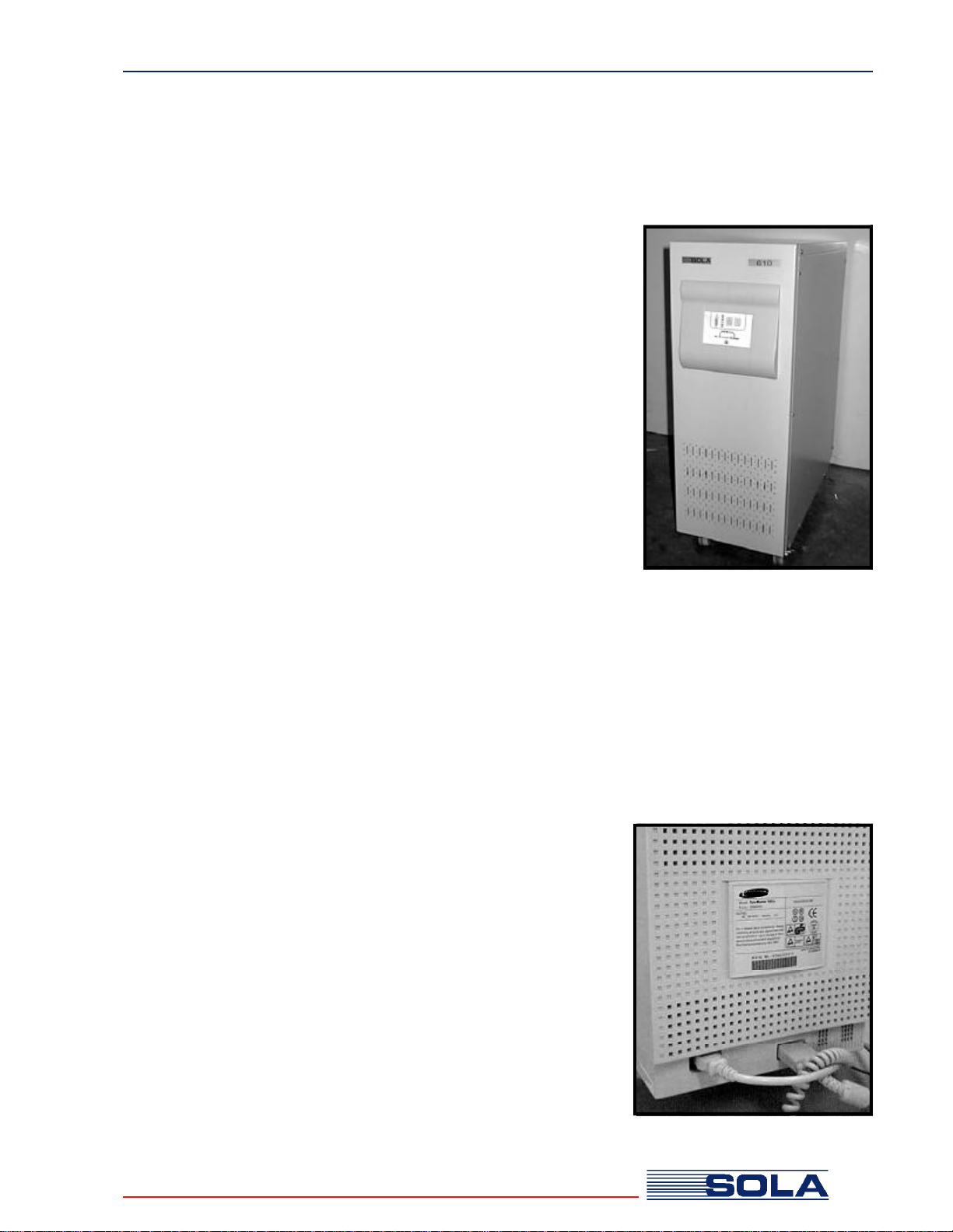
Check your equipment for the manufacturer’s label. This label
should state the equipment’s desired operating voltage (V) and
current (A) drawn by the equipment. The manufacturer’s label is
usually found on the external rear or underside of the equipment,
or in the handbook or operator’s manual.
Most computers and their related components are rated at
"worst case", with all of the expansion slots or bays fully loaded
at low line voltage, so your actual load is probably less than the
load indicated by the manufacturer.
2.1 IntroductionandProductDescription
2.2 Sizing your Load
An Uninterruptible Power System is designed to connect between
your utility supply wall outlet or distribution board and your critical
load. Its function is to continually monitor the availability and quality
of the electrical supply and to recreate the mains voltage to remain
within the UPS specifications, as detailed for each model.
Your SOLA 610 is an advanced true on-line sine wave UPS with
bypass line, utilising double conversion technology.
The utility power enters the UPS where it is rectified to a DC
voltage which will float charge the battery as well as run the DC to
AC inverter. The inverter generates the true sine wave output,
recreating the utility supply voltage. A bypass path is provided
through a transfer switch, should the UPS become overloaded or
aninverter faultoccur.
Because the UPS is an on-line design, conditioned power is
provided continuously to your load. During an electrical power
failure, the unit employs its internal maintenance free battery to
supply continuous power for as long as the battery is capable. The
UPS autonomy after a power failure will depend on (a) the size of
the UPS and the load of your equipment (b) the size of the battery
used (either the standard internal battery or external battery pack
options), and (c) the state of the battery and battery charge when the
power failure occurs. Batteries have a finite life that can be affected by
excessive use and/or high ambient temperatures. Under normal
operation, you should expect a 3-5 year life from your UPS battery.
1

SOLA 610 UPS Installation
The SOLA 610 UPS is designed to power all modern computer
equipment “loads”. The UPS output is specifically designed to
work with switching power supplies found in today's
microprocessor-based equipment.
SOLA does not recommend protecting laser printers
with this UPS. Laser printers have a heating cycle
which provides adhesion of the toner to the paper.
This heating cycle draws large amounts of electrical
current and will overload your UPS.
Most laser printers are not mission critical and can
therefore be protected with a power conditioner rather
than a UPS. Just be sure that the power conditioner
you purchase can accommodate the high inrush
currents of a laser printer. If your printer is mission-
critical and you want to protect it with a UPS, the UPS
must be sized to accommodate the high peak current
surge of the printer.
Although the packaging for your SOLA 610 was designed
specifically for this unit and serves it well in protecting the unit
from damage, you should unpack the unit immediately
and check for signs of concealed damage that may
have occurred in transit. Concealed damage is damage
that may not be apparent by the outside appearance of
the packaging.
In case of damage, please notify the delivering carrier
at once to examine the goods, regardless of the
external condition of the boxes. Under U.S. Shipping
Regulations, damage claims must be collected by the
consignee. Once your claim is established, damaged
merchandise may be returned for repair (see Page 33
for Return Policy). Do not return shipping-damaged
merchandise until after your claim has been
established with the carrier.
Do not destroy packing material or boxes until the
carrier's agent has examined them. Save all
packaging materials in case reshipment of the UPS
is required. Any damage sustained in transit when
shipped from the user, especially in an incorrect
container, will not be covered under warranty.
2.3 Types of Loads
2.4 Laser Printers and your UPS
2.5 Unpacking your UPS
2

SOLA 610 UPS Installation
Your UPS should be in a controlled environment. A controlled
environment is one that is indoor, temperature-controlled and free of
conductive or semi-conductive contaminants.The SOLA 610 is
intended for indoor use only. There should be adequate ventilation and
the location should be free of dust and fumes. Do not install the unit next
to open windows where uncontrolled environmental conditions could
affect the unit. Do not install the unit in any type of enclosure without first
calling SOLA Technical Support. The unit must have unrestricted air flow.
CAUTION
The environmental specifications shown in Table 1
(below) show the temperature and humidity limits of
the UPS. Do not exceed these limits.
2.6 UPSLocations
ENVIRONMENTALSPECIFICATIONS
Ambient Operating < 1500 m 0oC to 40oC (32oF to 104oF)
Temperature 1500 - 3000 m 10oC to 35oC
Ambient Storage All Models: -15oC to 40oC (5oF to 104oF)
Humidity All Models: 20% to 95%, non condensing
Altitude All Models: 8,000 feet (2500M) max.
To optimise the performance of your UPS we recommend you
ensure the battery is fully charged before you use the UPS to
support your critical load.
To recharge the battery, have your electrical contractor install
the UPS wiring to the hardwiring connections, as shown.
When power is supplied to the UPS (without operating any front
panel switches), the UPS will go through a short test sequence,
and the cooling fan will start.
On the front panel the line indicator and the bypass indicator will
illuminate. At this time there is power available at the output
terminals if the output circuit breaker is closed.
Table 1
2.7 RechargingtheUPSBattery
!
3
Input
Circuit
Breaker
External
Battery Option
Connection
Output
Circuit
Breaker
Input
Terminals Output
Terminals

SOLA 610 UPS Installation
Note
The battery backup feature of the UPS is
not available in this mode. See 3.1
“Switching on the UPS” to enable the
battery backup mode.
In this mode, (and normal UPS operating mode) recharging
occurs automatically and will take 10 hours if the batteries are
completely discharged. As UPS units are normally delivered with
charged batteries, providing the UPS has not been in storage for
a long time, it will not take long for the battery to reach full
capacity.
CAUTION
IN ALL CONDITIONS, if the UPS is connected
to a live supply, AC POWER IS PRESENT AT
THE UPS TERMINALS. The front panel OFF/
ON does NOT control the delivery of power to
the output receptacles.
External battery options can be fitted to increase the autonomy
when the UPS is operating during a mains failure. Refer Section
4.1 for selection of external battery options for your specific
UPS.
On the rear of the 6kVA UPS you will find an external battery
receptacle. For 10kVA models, the external battery is hardwired
to the terminal block. If you have purchased an external battery
option, it will be supplied with an interconnecting cable for this
purpose. Use only the matching battery option for your UPS
rating. Using the incorrect battery option may cause damage to
your UPS system. Once connected, your UPS will maintain the
charge in the external battery providing the utility mains is
available.
!
?
2.8 ExternalBatteryConnection
2.7 Rechargingthe UPSBattery(cont.)
External Battery Connector
6kVA UPS
4
External Battery Connector
10kVA UPS

SOLA 610 UPS Installation
2.9 InverterShutdownLink Installation
If your UPS has been delivered with the AS400
Card already installed, the inverter shutdown link
will be removed to avoid shipping damage.
Make sure the green remote inverter shutdown link
has a loop of wire in the terminals and firmly insert
it into the receptacle as shown.
IMPORTANT NOTICE: If the inverter
shutdown link
is not installed
with the wire
loop fitted, the
UPS inverter
WILL NOT
START.
Step 1
Step 2
Fitting the Inverter Shutdown Link
The Inverter Shutdown Link Fitted
5

SOLA 610 UPS Installation
Your UPS is fitted with a DB9 communications connector
on the rear panel, which can operate in two (2) modes. In
Mode 1 “Network Mode”, you can access opto coupled
outputs indicating mains failure or low battery and initiate
an inverter shutdown.
In Mode 2 “RS322 Mode”, RS232 serial communication is
available. This RS232 provides a proprietary command
sequence for the computer to monitor the utility and the
UPS status and to control the UPS output. The data
format of the RS232 is 2400bps, 8 bit data, 1 stop bit and
no parity.
The battery test mode is also available through the
RS232 command sequence whilst the UPS is operating
and the power is normal. During the test, the 4 LED’s
(line, bypass, battery and inverter) will light alternatively
until the test is completed.
Each UPS is supplied with a package of CHECKUPS II®
Advanced UPS communications software. This package
includes the correct interconnection cable for your SOLA
610 UPS. If your computer does not have a DB9
connector on the serial port, use a standard DB9-DB25
adaptor, available at most computer accessory stores.
The CD-ROM provided with your UPS includes software
for many standard operating systems and detailed
manuals in Adobe Acrobat format. All utilities required to
read and/or print the manuals are included on the CD-
ROM. Refer to section 4.2 & 4.3 for more details of
CheckUPS II® and it’s capabilities.
If you have purchased an AS400® card option, this will be
installed in the communications slot. Be careful to connect
your AS400® interface cable to the correct DB9
connector. Refer to Section 4.4 for more details of the
AS400® card option.
If you have purchased an SNMP option card, this will be
fitted into the communications slot. Only one (1) card,
either AS400® or SNMP can be fitted into the slot at any
one time. Refer Section 4.5 for more details of the SNMP
Card option.
With the SNMP option card fitted to the UPS, the RS232
communication is no longer available on the DB9
CommunicationsConnector.
2.10 Settingup the UPSMonitoring from your Computer
DB9
12345
6789
RS232 Mode
Pin Assignment
GND RX
12345
6789
Remote
Shutdown
SeeNote1
N/O,closes
onLow
Battery
N/C,opens
onInput
Powerfailure
N/O,closes
onInput
Powerfailure
Note 1
Remote shutdown when in battery mode
only (i.e. no input mains power).
Keeping this pin high (+5~+12V) for 500ms
will turn off the UPS inverter when no input
mainspresent.
TX
Network Mode
Pin Assignment
6

This page intentionally left blank.
7

SOLA 610 UPS Operation
Inverter
After completing the installation and battery
recharge, ensure the input circuit breaker and the
output circuit breaker on the rear panel are both in
the ON position. Switch on the UPS by pressing the
front panel switch ‘I’ for at least 2 seconds. The unit
will now commence a system check sequence
before establishing it’s own inverter power.
Firstly, all the Load Level LEDs will illuminate
together then one by one. Within a few seconds the
Inverter indicator will illuminate, indicating the
inverter has now started and the bypass indicator
will extinguish indicating that the UPS is now in
normal mode.
If the Line indicator flashes and the battery
indicator illuminates at the same time, your
incoming utility AC source voltage and/or frequency
is out of the UPS specification. The UPS is drawing
energy from the batteries.
You may now start the critical equipment that you
connected to the UPS. If the load level indicator
exceeds 100% and the audible alarm sounds twice
per second, you have plugged too many items into
the UPS and overloaded it. Remove the non critical
items and check the load level indicators.
When the utility AC source fails, the UPS will
continue to deliver output to the UPS receptacle
from the internal or external batteries and the UPS
inverter. When this occurs, an audible alarm will
sound every 4 seconds and the “line” indicator will
extinguish. The battery indicator will be illuminated
to show that the battery is now being discharged.
The audible alarm can be silenced by pressing the
“I” push button on the front panel. If the battery
continues to discharge until the low battery charge
point is reached, the audible alarm will sound
again. At any time, the audible alarm can be
reactivated by pressing the “on” switch on the front
panel.
3.1 Switching on the UPS
3.2 When the Power Fails
}
Fault Overload
Line
Bypass
Load Level
and Runtime
lights
Battery
InverterBattery
8
Off
On

SOLA 610 UPS Operation
3. 4 Front Panel Indicators
When the utility AC Line returns after a power failure, the Line
indicatorwill illuminate again,the audible alarmwill silence and
the UPS will automatically commence the recharging of the
battery. The battery indicator will go out and the UPS will return
tonormal operation.
Your SOLA 610 UPS is fitted with 10 indicators to provide you
with a simple but comprehensive explanation of the UPS status,
The function of these LED indicators are detailed below:-
3.3 When the Power Returns
}
Fault
Overload
Line
Bypass
Runtime
9
This will illuminate when a fault condition
occurs in the UPS. At this time the
audible alarm will sound continuously.
This will illuminate when the UPS is
overloaded.
These perform two functions during different
operating modes of the UPS. When utility AC
mains is present, these will show the
equipment load connect as a percentage of
the UPS capacity in 25% increments.
When the UPS is in battery mode, these
lights will show the amount of battery
capacity remaining as a percentage of the
full battery capacity in 25% increments.
This light illuminates when the bypass line is
in use and the UPS power is being sourced
directly from the utility AC supply. When
starting the UPS the bypass line will always
be in service with the light illuminated until
the inverter has started and accepted the
load.
This light will illuminate when there is normal
AC voltage entering the UPS from the utility
supply.
This light illuminates during mains failure,
showing that the battery is discharging.
This inverter light should be on during
normal (utility available) or mains failure
mode. When OFF, the UPS cannot provide
battery backup power.
Load Level
Battery
Inverter
OFF
Switch ON
Switch

SOLA 610 UPS Optional Features
External battery packs may be connected to the SOLA 610
UPS.
The standard battery packs available are listed below:
4.1ExternalBatteryOptions
*Runtimes are approximate and depend on state of
charge of batteries at time of power failure, ambient
temperature, connected load, age of battery, etc.
Larger runtimes are available on request.
#When using this battery pack option, batteries internal
to the UPS are removed.
10
Part NumberTo Suit UPS
ModelUPS Rating
(kVA)
* Runtime with UPS
and additional battery
pack
Half LoadFull Load
0610-1BAT-60000610-6000A646 min23 min
0610-2BAT-60000610-6000A677 min36 min
0610-3BAT-60000610-6000A6191 min75 min
0610-1BAT-010K# 0610-010KANB1050 min20 min
0610-2BAT-010K# 0610-010KANB10100 min33 min

SOLA 610 UPS Optional Features
4.2 Installingthe CheckUPSII®Software
Each Sola 610 UPS is supplied with CheckUPS II® Software, a
sophisticated UPS Monitoring and orderly unattended system
shutdown utility for most popular operating systems.
The CheckUPS II® Suite is contained on the CD-ROM in the
software pack along with a special cable for use with your SOLA
610. On the CD-ROM you will find versions of the CheckUPS
II® software to operate on DOS, Windows® v 3.11, Windows
95®,Windows NT®, OS/2,Novell®/Windows® 3.11, Novell®/
DOS and various UNIX platforms.
On line manuals (Adobe Acrobat and/or ASCII text) are also
included on the CD-ROM, along with the Adobe Acrobat reader
utility.
Installation
The CheckUPS II® Suite master installation program will auto-
detect which operating system you are running, and ask you
which UPS model you have connected to your system. Then it
will launch the appropriate software installation program.
Verify that the UPS is turned on and connected to the PC. Exit
any other currently running programs. Insert the CheckUPS II®
Suite CD-ROM into your drive and launch the appropriate install
program from the following choices:
All operating systems except OS/2 and UNIX:
Run D:\INSTALL.EXE
OS/2 users:
Run D:\OS2\INSTALL.EXE
During installation, you will be asked if you want to install the on-
line manual onto the local hard drive (recommended).
UNIX and UNIX-like system users:
If your UNIX system is capable of reading an ISO9660 CD-
ROM: Mount CD-ROM
Change directory to /UNIX
Run UNIXINST
11

SOLA 610 UPS Optional Features
4.2 InstallingtheCheckUPSII®Software(cont.)
If your UNIX system cannot mount and read the CD-ROM,
please copy/transfer from a DOS/Windows system onto your
UNIX system:
SOLA UPS users:
D:\UNIX\SOLAUNIX.TAR
D:\UNIX\UNIXINST
When you have the files on your UNIX system (preferably
in root):
Run UNIXINST
For UNIX users, an ASCII text based manual will be
automatically copied onto the hard drive.
If you wish to install an Acrobat-basd manual at a later
time, re-run the install program as already described and
select Install manual only. Once you have installed the
software it will either start running automatically, or you will be
returned to the operating system.
This completes CheckUPS II® software installation.
Installation Troubleshooting
If for some reason the master installation program does not
properly auto-detect your operating system, you may manually
select an install program for your UPS by running:
DOS users:
Run D:\DOS\INSTALL.EXE
Novell Netware/Win v3.1 Workstation users:
Run D:\WIN_31\SOLA31.EXE
Novell Netware®/DOS Workstation users:
Run D:\DOS\INSTALL.EXE
Windows NT® users:
Run D:\WIN_NT\SOLANT.EXE
Windows 95® users:
Run D:\WIN_95\SOLA95.EXE
Windows® v3.11 users
Run D:\WIN_31.SOLA31.EXE
OS/2 users:
Run D:\OS2\INSTALL.EXE
12
Other manuals for 610
1
This manual suits for next models
2
Table of contents
Other Sola UPS manuals