9
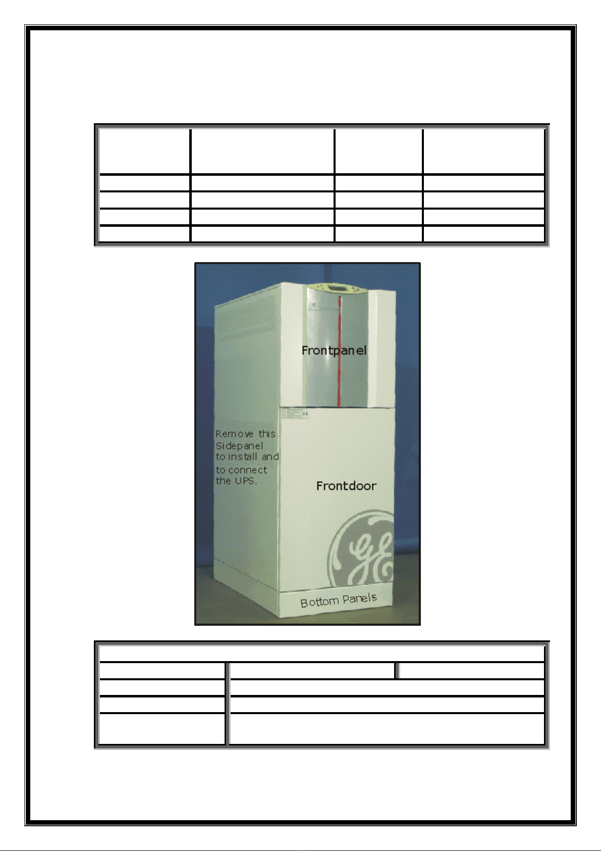
Startup in Service Mode (Q1 open)
Connect Mains voltage (Utility) to the UPS.
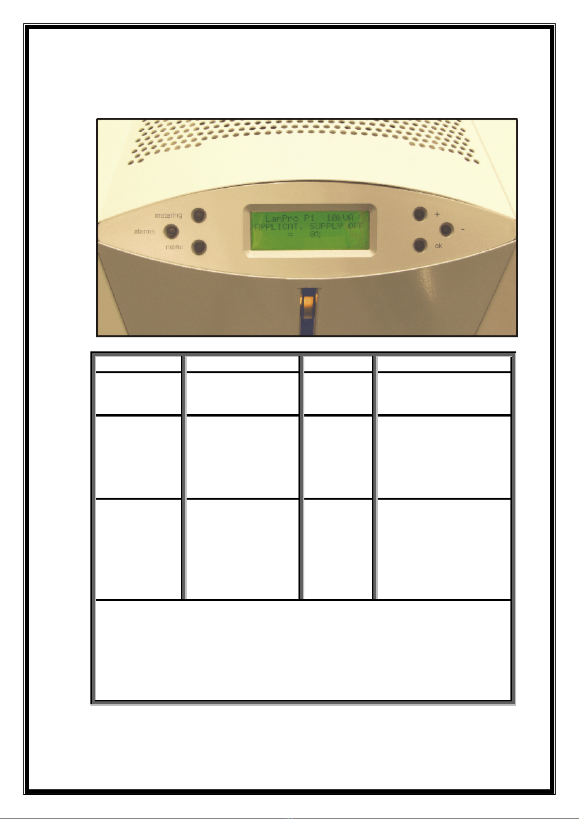
The Electronics are now powered. Control selftest on the
display. At the end of selftest, the first page is displayed
Example of first page (Series 0)
The yellow LED on the Frontpanel should now be constantly
ON, indicating Q1 to be open, thus the UPS in service mode.
Startup in Service Mode
•Close Mains (Utility) fuses.
•Verify in measurements for identical values of the Bypass
(Mains)and Rectifier voltages.
•Press now simultaneously the keys "metering" and " +".
•Precharge of the DC Capacitors starts and at ca. 250 Volts
K4 will close. Press metering and verify for voltages UDCP
and UDCN a value of ca. 315V, with Mains voltage = 230V.
•Press again simultaneously keys "metering" and "+" to
start the Booster, which will bring the DC Voltages up to
+/- 400 Volt. Verify again in "metering" for UDCP and
UDCN show a correct reading of these voltages.
•Go now in the menu to Inverter ON / OFF page, and start
the Inverter. Verify in measurements for correct voltages.
(220, 230, 240 Volt) Compare with PIOR.
•Press Inverter ON a second time to activate the Bypass
(K6 and SSM) but also K7 closes while the Inverter is shut
down. Verify for identical reading of Load and Bypass.
voltages, since the Bypass is now connected to the output
•At this point the ventilators must be running.
•Press Inverter ON a third time to transfer the output from
Utility to Inverter, at this moment the Inverter restarts
again, however without softstart, but with full output
voltage. Verify for Inverter output voltages in the
measurement screen for Load.


 Plus Startup manual")