TDS e28 User manual

E28
UserManual
E28
Board
EPICSBC supportsIntelATOMN270
Processor
withGigabitLAN / LVDS/TVout/
2COM / WIFI
User
Manual
Manual
Rev.
:
1.0
BookNumber: E28-2009.08.06
1

E28
UserManual
Revis
i
on
2
Version Date Author Description
1.0 2009.08.06
chenyon
g
Initialrelease.

E28
UserManual
Copyright 2009
All Rights
Reserved.
Manual sfirst edition:
Forthe purposeofimproving reliability,design andfunction,the informati
oninthisdocumentis
subjecttochangewithoutpriornoticeanddoesnotrepresentacommitmenton the partof
the
manufacturer.
Inno eventwillthemanufacturerbe liablefordirect, indirect, special,incidental,orconsequentia
l
damagesarisingoutofthe useorinabilitytousetheproductordocument
ation,even ifadvisedof
the possibilityof suchdamages.
Thisdocumentcontainsproprietaryinformationprotected bycopyright.All right
sarereserved.No
partofthismanualmaybe reproduced byanymechanical,electronic,orothermeansinanyform
without priorwritten permissionof themanufacturer.
Trademarks
E28 isaregisteredtrademarks ofWTM; IBMPCisaregistered trademarkof the International
Business MachinesCorporation; Pentiumisaregistered trademarkof IntelTechnologiesInc;
Awardisaregistered trademarkof AwardSoftwareInternationalInc; otherproduct names
mentioned hereinareused foridentification purposesonlyand maybe trademarks
and/orregistered trademarks of theirrespectivecompanies.
3

E28
UserManual
T
a
ble
of Conten
t
s
1Introduction
....................................................................
.....................
5
1.1Specifications.....................................................................................................................
6
1.2PackageContents..............................................................................................................
7
2H/WInformation
.............................................
.....................................
9
2.1Locations(TopSide)..........................................................................................................
9
2.2Locations(BottomSide)..................................................................................................10
2.3ConnectorandJumperSetting.......................................................................................1
1
3BIosSetting
.......................................................................................
16
3.1MainSetup........................................................................................................................
17
3.2AdvancedSetup...............................................................................................................
18
3.3PowerSetup.....................................................................................................................
19
3.4PnP/PCISetup..................................................................................................................
20
3.5PeripheralsSetup.............................................................................................................
21
4BIOSRefreshing,
W
a
tchDog and GPIOProgramming
..................
26
4.1BIOSRefreshing...............................................................................................................
26
4.2WatchDogProgramming.................................................................................................27
4.3
GPIO
Programm
i
n
g
................................................................................................
.........
.
3
1
5Electrical Characteristics
.................................................................
36
5.1BasicElectrical Characteristics Table............................................................................
36
4

E28
UserManual
INTRODUCTION
W
elcome
to
the
E28
Compute
r
.
The
E28
is
a
Intel
945GSE
chipset
based
platform
designed
for
low
power
consumption
and
wide
operating
AtomN270 processor, whilecoming witha533MHzFront Side Bus.
tempera
t
ure.
It
suppor
t
s
the
5
1

E28
UserManual
1.1
S
p
ecifications
l
Processo
r
:
on
-
boardIntel
AtomN270
n
n
n
n
n
Single
core
and
suppor
t
s
2
-
Threads.
1.6GHzcorefrequency.
533MHzFSB.
512KBsL2 cache.
2.5WlowTDP.
l
Chi
p
set
-
North
Bridge:
Intel
945GSE
n
n
n
One SODIMM socket suppor
t
sDDR
533/400
SODIMM
and
ca
p
acity
up
to
2
GBs
max.
DVMT3.0supports224MBsgraphics memorymax. (shared withsystemmemory).
Analog displaysupports400MHz/256-bit RAMDAC, resolution QXGA
(2048x1536@75Hz).
18-bit/36-bit LVDSsupportsSingle/DualchannelLCD,resolutionUXGA(1600x1200).
TV-OUTsupportsHDTV, 480P/720P/1080P/1080I.
n
n
l
Chi
p
set
-
South
Bridge:
Intel
82801GM
n
n
n
n
n
n
T
w
oS
A
T
A
connectors.
HD AudioCodecALC662 supports5.1CH. audiooutput.
One PCI-eGbEcontrollers –RTL8111DL-support 1000/100/10 MbpsLANs.
Eight USB2.0ports.
Supports+3.3VCompactFlashType cardwithUltra-DMAmode 2/1/0.
Mini-PCIEsupportsOnePCIEdeviceswithPCIEBusMastermode.
l
SuperI/O:F
1862FG
n
n
n
n
n
Int
ernal
W
a
tchDog,
programmable
1~255
second(s)/m
i
nute(s).
8bitsprogrammablebi-direction GPIOs,TTL-3.3V.
Twoserialports, supportsRS232.
TwoDC fan connectors, onesupports
ON/OFFcontrolbysystemtemperature.
Hardwaremonitorforvoltage, fan speedand temperature.
l
Others
n
n
n
n
n
Power
requirement:
+12Vdc
input
only
(+12V@2.1A
typical
l
y
)
.
Operating temperature: -40~75℃(-40~167℉). [cold-start@-20~75℃(-4~167℉)]
.
Storage temperature: -40~85℃(-40~185℉).
Relativehumidity: 0~90%@40℃(104℉), non-condensing.
Dimension: 165 mmx115 mm.
6

E28
UserManual
1.2PackageConten
t
s
Check
if
the
following
items
are
i
ncluded
in
the
p
ackage.
l
l
l
E28
EPICS
BCboard
Quick Manual
SoftwareUtilityCD
7

E28
UserManual
1.3BlockDiagram
8

E28
UserManual
H/WINFORM
A
TION
This
chapter
describes
the
ins
t
allation
of
E28
.
First,
it
shows
the
function
diagram
and
the layout ofE28.Thendescribesthe unpacking information whichyou shouldreadcarefully, as
well asthe jumper/switchsettingsfortheE28 configuration.
2.1
Locations
(
T
op
Side)
9
2

IDE1 LVDS1 JP2
JBAT FP1 INVERTER1
JP4JP5 GPIO1
VGA
ATX12V JCOMP1JCOMP2 TV_OUT
USB3USB4 AUDIO2 LAN1
PWOUT1 CHAFANSFAN1 PS1
SATA1 MIC1 USB1USB2
SATA2 LINE_OUT1 JP3
BAT1 COM1COM2 DC_JACK
AV MINI_PCIE1 KB/MS2
VGA1 PARALLEL1
E28
UserManual
10
SODIMM1
U2U3
CF1

E28
UserManual
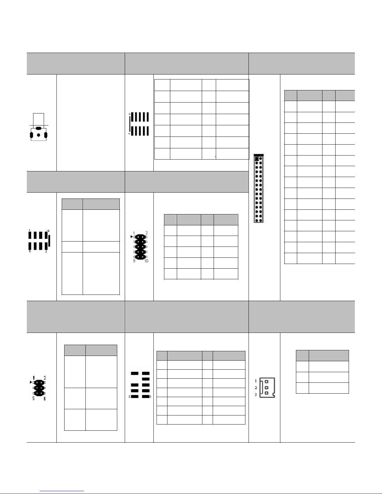
2.3Connectorand JumperSetting
11
1.
IDE1:IDE144pinconnector.
2. JBAT:CMOSdata
retention/clear. 3. JP4JP5:USBPOWER
connects
IDE144pin connector.
4.
ATX12V:External +12VDC
po
werinputconnector.
5. USB3USB4:Internal
USB2.0connector. 6. PWOUT1:Extra+12V
and+5V
DC pow
eroutputconnector(for
SATAdevice).
7.
SATA1:SATAdevice
connector
#1. 8. SATA2:SATAdevice
connector#2.
9. BAT1:CMOSbatteryholder.
SATAdevice connector#1.
SATAdevice connector#2.
CMOSbatteryholder.
PIN
SETTING
1
+12V
2
GND
3
GND
4
+5V
PIN
SETTING
1
GND
2
GND
3
+12V
4
+12V
PIN
SETTING
PIN
SETTING
1
+5V
2
+5V
3
USB3-
4
USB4-
5
USB3+
6
USB4+
7
GND
8
GND
9
GND 10
GND
STATUS
SETTING
1-2
USBPOWER
ONDISABLE
(Default)
2-3 USBPOWER
ONENANLE
STATUS
SETTING
Open
CMOSdata
retention.
(Default).
Short
CMOSdataClear
E28
UserManual
12
10.
AV:Infrareddevice
connecto
r. 11. VGA1:ExtraVGAsignal
connector. 12. LVDS1:LCD panel (LVDS,
18-bit/36-bit)connector.
AVdevice connector.
E: Ev
enfordual channel.
O:Oddforsinglechann
el.
13.
FP1:Frontpanel
connecto
r. 14. GPIO1:8-bitTTL-3.3VGPIO
connector.
15.
JCMOP1JCOMP2:
COM
9pin5Vor12V
selection.
16.AUDIO2:5.1channelsAudio
signal connector.
17. CHAFANSFAN1:
SystemDC fanconnector.
ON/OFF controlled by
system temperature setti
ng
ofBIOS.
PIN
SETTING
1
GND
2
+12V
3
Fanspeeddata
PIN
SETTING PIN
SETTING
1
MIC2_L
2
NC
3
MIC2_R
4
GPIO
5
LINEOUT2-R
6
GND
7
SENSE_B
8
9
LINEOUT2-L
10
GND
STATUS
SETTING
1-2
RS232.
(Default)
3-4
12V.
5-6
5V.
PIN
SETTING
PIN
SETTING
1
+3.3V
2
GND
3
GPIO[50]
4
GPIO[54]
5
GPIO[51]
6
GPIO[55]
7
GPIO[52]
8
GPIO[56]
9
GPIO[53]
10
GPIO[57]
STATUS
SETTING
1-3
2-4
HD_LED.
PW_LED
5-7
Reset
6-8
PW_BN
PIN
SETTING
PIN
SETTIN
G
1
VCC
2
VCC
3
VCC-
4
GND
5
GND
6
GND
7
RX00-
8
RX00+
9
RX01- 10
RX0
1+
11
RX02-
12
RX02+
13
GND 14
GND
15
RX0C- 16
RX0C+
17
RX03- 18
RX03+
19
RXE0- 20
RXE0+
21
RXE1- 22
RXE1+
23
RXE2- 24
RXE2+
25
GND 26
GND
27
RXEC-
28
RXEC+
29
RXE3- 30
RXE3+
PIN
SETTING PIN
SETTING
1
RED
2
GND
3
GREED
4
GND
5
BULE
6
GND
7
8
9
HSYNC
10
GND
11
VSYNC
12
5V
DDC_CLK
DDC_DAT
A

E28
UserManual
13
18.
MIC1:
connector
forMIC. 19. LINE_OUT1:
connectorforAUDIO OUT. 20. COM1COM2:RS232 sig
nal
connector.
connectorforMIC.
21.
MINI_PCIE1:
connector
forMINI_PCIE1. 22. PARALLEL:LPT
connector. 23. JP2:LCD panel driving
voltageselection.
24.
INVERTER1:LCD panel
inverter
po
w
erconnecto
r
.
25. VGA:D-SUB-15 female
connectorforVGAoutput. 26.TV-OUT:TV-outsignal
connector.
D-SUB-15 femaleconnector
forVGAoutput.
PIN
SETTING PIN
SETTING
1
S-Y
2
GND.
3
GND
4
AV.
5
S-Pr
6
PIN
SETTING
1
GND
2
GND
3
BKL_CTL
4
BKLEN
5
12V
6
12V
STATUS
SETTING
2-3
+3.3VforLCD
panel.
(Default).
1-2
+5VforLCD panel.
connectorforMINI_PCIE1
PIN
SETTING
PIN
SETTING
1
STB-
2
AFD-
3
PD0
4
ERR-
5
PD1
6
INIT-
7
PD2
8
SLIN-
9
PD3
10
GND
11
PD4
12
GND
13
PD5
14
GND
15
PD6
16
GND
17
PD7
18
GND
19
ACK-
20
GND
21
BUSY
22
GND
23
PE
24
GND
25
SLCT
PIN
SETTING
PIN
SETTING
1
DCD
2
DSR
3
RX
4
RTS
5
TX
6
CTS
7
DTR
8
RI
9
GND
10
NC
connectorforAUDIO OUT
E28
UserManual
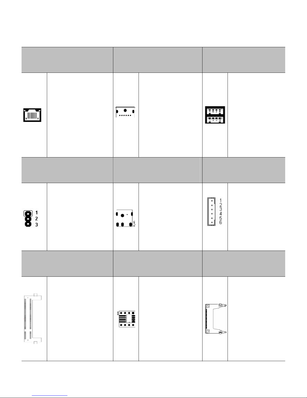
14
27.
LAN1:RJ45 connectorfor
GigabitE
thernetport#1.
28. PS1:KB+MS
connectorforport.
29. USB1USB2:USBA-type
stackconnectorforUSB2.0
port,
RJ45 connectorforGigabit
Ethernet port#1.
Wake-On-LANsupported.
KB+MS connectorfor
port.
Upper:Port#2.
Lower:Port#1.
30.
JP3:CFMasterorSlave
Selection
.31. DC_JACK:power12V
inputconnector.
32. KB/MS2:KB+MS
Extraconnector.
1-2:MASTER
2-3:SLAVE.
power12V
inputconnector.
33.
SODIMM1:200-pin
un
-bufferedDDR SODIMM
socket.
34. U2U3:BIOSsocketfor
flashEEPROM(systemBIOS
access).
35. CF1:Type compact
flash
cardsocket.
SupportsDDR
533/400MHzun-buffered
and non-ECC SODIMM.
Capacityis2GBs max.
BIOSsocketforflash
EEPROM.
+3.3VCF cardonlyand
UDMAmodesupported.

E28
UserManual
NOTE
1:
FP1:Frontpanel connector.
15
STATUS
SETTING
1-3
2-4
HD_LED
PW_LED
5-7
Reset
6-8
PW_BN.

E28
UserManual
BIOSSETTING
This
chap
t
er
describes
the
BIOS
menu
dis
p
lays
and
explains
how
to
perform
common
tasks
needed togetthe systemup and running.It alsogivesdetailed explanation ofthe elements
found
ineachof the BIOSmenu displays. The following topics arecovered:
l
l
l
l
l
l
l
l
Main
Setup
Advanced Setup
PowerSetup
PnP/PCI Setup
Peripherals
Setup
PCHealthSetup
Boot Setup
Exit Setup
Once
you
enter
the
BIOS
CMOS
setup
utility,
you
can
use
the
control
keys
that
listed
a
t
the
bottomof the menu toselectthe desired valueineachitem.
16
3

E28
UserManual
3.1Main Setup
17
Option Choice Description
DateSetup
N/A
Tosetthesystemdate.Notethatthe ‘Day automatically
changeswhen you set the date.
TimeSetup
N/A
Toset the systemtime.
IDEChannel 0
Master/Slave
IDEChannel 2
Master/Slave
N/A
Press <Enter>toviewthe IDEdevicesinformation and
related parameters.
HaltOn
All Errors,
NoErrors,
All, But
keyboard.
Toselectthe situation inwhichyou wanttheBIOStostop
the POSTprocess andnotifyyou.
E28
UserManual
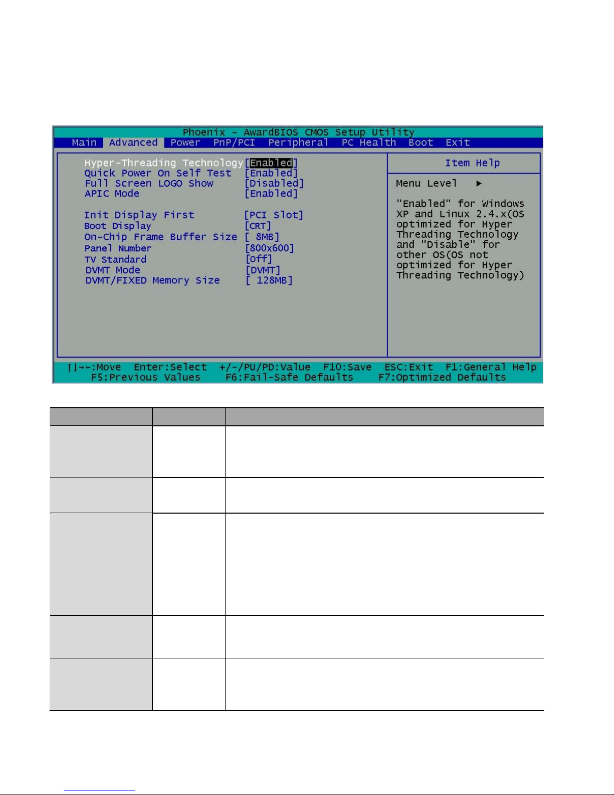
3.2Advanced Setup
18
Option Choice Description
Quick PowerOn
SelfTest
Enabled
Disabled
ThiscategoryspeedsupPowerOnSelfTest(POST)afteryou
havepowered upthe computer. If itisset to Enabled, BIOSwill
shorten orskipsomecheck itemsduring POST.
Full ScreenLogo
Show Enabled
Disabled Select Enabled toshowthe OEMfullscreenlogo ifyou
have
add-inBIOS.
BootDisplay
CRTLVDS
CRT+LVDS
TV
CRT+DVI
Toset the displaydevice.
Panel Type
800x600
1024x768
Toset the LVDSpanelresolution that youwant.
DVMTmode
FIXED
DVMT
Both
Toset themode of DynamicVideo MemoryTechnology
(DVMT).

E28
UserManual
3.3PowerSetup
19
DVMT/FIXED
MemorySize
64MB
128MB
224MB
Toset the shared memorysizeforDVMT.

E28
UserManual
3.4
PnP/PCI
Setup
20
Option Choice Description
Reset
Configuration
Data
Enabled
Disabled
Normally,you leavethisfield Disabled.Select Enabled
to
resetExtended SystemConfigurationData(ESCD)when
you
exitsetup.If you haveinstalled anewadd-onand the
system
reconfigurationhascaused suchaseriousconflict,then the
operatingsystemcan not boot.
Resources
ControlledBy
Auto(ESCD)
Manual
The AwardPlug and PlayBIOShasthe cap
acityto
automaticallyconfigureallof
the bootandPlug and Play
compatible devices. However, thiscapability
means
absolutelynothing unless you areusing aPlug and Play
operatingsystemsuchasWindows95.If yousetthisfield
to
“manual,”then you maychoosespecificresourcesbygoing
intoeachof thesubmenus.
IRQ Resources
N/A
When resourcesarecontrolled manually,assign atype
to
eachsysteminterrupt,dependingon the typeofthe device
that usesthe interrupt.
Table of contents


