Mapping the Inputs and Outputs for Each Device
The PP24 consists of 3 banks of BNC connectors, Bank A, B, and C. Each of the banks is
labeled 1-8 within the set and each BNC is also numbered as part of the entire group from 1 -
24.
The following table shows the conguration of the BNC connectors for each I/O connector of
the RX and RZ devices.
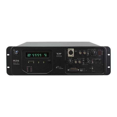
For more information, see the diagrams for the desired device below.
The thumbscrews should never be completely removed. Avoid loosening the thumbscrews too far.
Device & Connector A1 - A8 B1 - B8 C1 - C8
RZ5, RZ5D, RZ5P, RZ6, RZ10x
Digital I/O Connector
Digital I/O
Port C Bits 0-7
Digital I/O
Port A Bits 0-7
Digital I/O
Port B Bits 0-7
RZ2
Digital I/O Connector
Digital I/O
Port C Bits 0-7
Digital I/O
Port A Bits 0-7
Digital I/O
Port B Bits 0-7
RX5, RX6, RX7, RX8
Digital I/O Connector
Bit Addressable Digital I/O
Bits 0-7
Digital I/O
Byte A Bits 0-7
Digital I/O
Byte B Bits 8-15
RX5, RX7
Multi I/O Connector
Analog Outputs
A2, A4, A6, A8 = Channels 1-4
A1, A3, A5, A7 = Not Used
Digital I/O
Byte C Bits 16-23
Digital I/O
Byte D Bits 24-31
RX8
Analog I/O Connector
Analog I/O
Block A Channels 1-8
Analog I/O
Block B Channels 9-16
Analog Output
Block C Channels 17-24
PP24 Patch Panel | 5


