TE Connectivity Crimp Quality Monitor II User manual

Crimp Quality Monitor II
Part number 2359600-1
Customer Manual
412-10100
22 SEP 2022 Rev D
Original instructions

412-10100
Rev A
2 of 74
General information
The information provided is intended solely for product description purposes. Users must carry out their
own assessments and tests. Our products are subject to natural wear and aging processes.
All rights are retained by TE Connectivity (TE) in case of applications for protective rights. We reserve
all rights of disposal, such as copying and transfer rights.
The front cover shows a sample configuration. The supplied product may vary from what is shown.
This operating manual is only intended for internal use by the user of the crimping machine for FFC
and F crimping (referred to herein as "FFC-FFC-CM") and their personnel.
The relevant supplementary operating manual contains descriptions, technical drawings, specifications
and instructions, no part of which may be reproduced, circulated, disclosed, or used for the purpose of
competition without permission.
Should third parties endeavor to gain access to this operating manual, the same fairness is expected
from you as you would expect from your customers in such cases.
All rights reserved, including the granting of patents or other registrations. Subject to technical
changes.
© Copyright 2022 TE Connectivity Ltd. family of companies. All rights reserved.
TE Connectivity, TE Connectivity (logo), and TE (logo) are trademarks. Other logos and product or
company names may be trademarks of their respective owners.
PRODUCT INFORMATION 1-800-522-6752
This controlled document is subject to change.
For the latest revision and Regional Customer Service, visit our website at www.te.com.

412-10100
Rev A
3 of 74
Contents
1Introduction..................................................................................................................................................... 7
2Description ................................................................................................................................................... 10
2.1 Screen description ............................................................................................................................... 10
2.2 Menu Bar ............................................................................................................................................. 10
2.3 Control Panel Screen .......................................................................................................................... 11
2.4 Help ..................................................................................................................................................... 12
2.5 Screen Information .............................................................................................................................. 12
2.6 Graphing Information........................................................................................................................... 12
2.7 Task Bar .............................................................................................................................................. 13
2.8 Definitions ............................................................................................................................................ 13
2.8.1 Headroom (and how it affects crimps)............................................................................................. 13
2.8.2 Crimp Height.................................................................................................................................... 13
2.8.3 Work index....................................................................................................................................... 14
2.8.4 Peak force........................................................................................................................................ 14
2.8.5 Point-to-point (P2P) analysis ........................................................................................................... 14
2.8.6 Fast Fourier transform (FFT) analysis ............................................................................................. 14
2.8.7 Force Only Mode ............................................................................................................................. 14
3Receiving, inspection, and installation ......................................................................................................... 15
3.1 Receiving and inspecting..................................................................................................................... 15
3.2 Installation............................................................................................................................................ 15
3.3 System settings ................................................................................................................................... 16
3.4 CQM settings ....................................................................................................................................... 16
3.4.1 Setup Tab ........................................................................................................................................ 17
3.4.2 Position Sensor Tab ........................................................................................................................ 18
3.4.3 Force Sensor Tab ............................................................................................................................ 19
3.4.4 Sensor Calibration Tab .................................................................................................................... 19
3.4.5 Learn Tab ........................................................................................................................................ 20
3.4.6 Control Limit Tab ............................................................................................................................. 21
3.4.7Graphing Tab................................................................................................................................... 21
4Production run setup .................................................................................................................................... 22
4.1 Options ................................................................................................................................................ 22
4.2 Work Order .......................................................................................................................................... 22
4.3 Order Size............................................................................................................................................ 23
4.4 Part ...................................................................................................................................................... 23
4.5 Analysis Methods................................................................................................................................. 24
4.6 Crimp Height........................................................................................................................................ 25
4.7 Peak Force (PF) and Work Index (WI) Sensitivity............................................................................... 26

412-10100
Rev A
4 of 74
4.8Point to Point (P2P) / FFT Sensitivity .................................................................................................. 27
4.9 Sample................................................................................................................................................. 28
4.10 Calibrate .............................................................................................................................................. 29
4.11 Learn.................................................................................................................................................... 30
5Production .................................................................................................................................................... 32
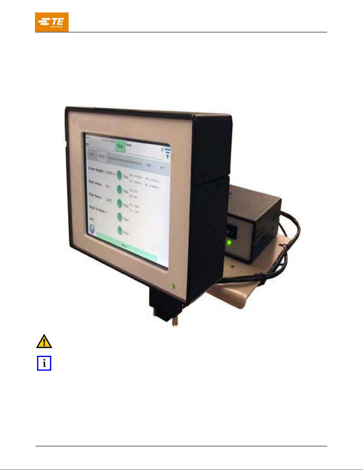
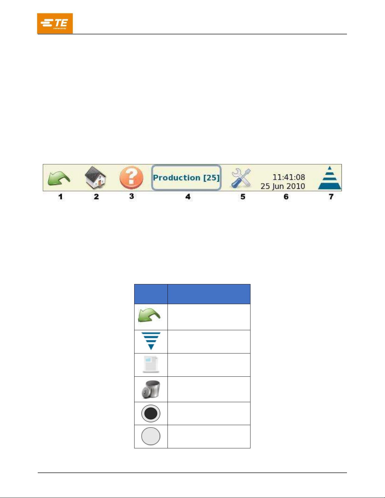
5.1 Basic Screen........................................................................................................................................ 33
5.2 Status................................................................................................................................................... 34
5.3 Crimp Height........................................................................................................................................ 35
5.4 Work Index........................................................................................................................................... 36
5.5 Peak Force .......................................................................................................................................... 37
5.6 P2P ...................................................................................................................................................... 38
5.7 FFT ...................................................................................................................................................... 39
6Control panel ................................................................................................................................................ 40
6.1 Language icon ..................................................................................................................................... 40
6.2 Login/Logout ........................................................................................................................................ 40
6.3 Users ................................................................................................................................................... 41
6.3.1 Add New User.................................................................................................................................. 41
6.3.2 Change Password ........................................................................................................................... 41
6.3.3 Delete .............................................................................................................................................. 41
6.3.4 Permission Settings ......................................................................................................................... 42
6.4 Locale Settings .................................................................................................................................... 44
6.4.1 Date/Time Settings .......................................................................................................................... 45
6.4.2 Reports ............................................................................................................................................ 46
6.4.3 Report Setup.................................................................................................................................... 53
6.4.4 Curve History Graph ........................................................................................................................ 53
6.4.5 Network............................................................................................................................................ 54
6.4.6 Display Settings ............................................................................................................................... 56
6.4.7 Calibrate Touchscreen..................................................................................................................... 57
6.4.8 Maintenance .................................................................................................................................... 58
6.4.9 Diagnostics ...................................................................................................................................... 62
6.4.10 Error Log Viewer.......................................................................................................................... 66
6.4.11 Demo ........................................................................................................................................... 67
6.4.12 Printer Icon .................................................................................................................................. 67
7Troubleshooting............................................................................................................................................ 69
7.1 Additional information for specific sensors .......................................................................................... 70
7.1.1 Linear Encoder ................................................................................................................................ 70
7.1.2Analog Height Sensor...................................................................................................................... 70
7.1.3 Base Plate Strain Gage (Force Sensor) .......................................................................................... 71

412-10100
Rev A
5 of 74
7.1.4 Piezo Sensor (Force Sensor) .......................................................................................................... 71
7.1.5 Trigger Sensor (on non-TE terminators).......................................................................................... 71
8Maintenance................................................................................................................................................. 72
8.1 Touch screen cleaning ........................................................................................................................ 72
8.2 Daily maintenance ............................................................................................................................... 72
8.3 Special handling precautions for systems with the linear encoder installed ....................................... 72
8.4 Quality control maintenance ................................................................................................................ 73
9Evaluation and repair ................................................................................................................................... 73
10 Revision summary ................................................................................................................................... 73

412-10100
Rev A
6 of 74
SAFETY PRECAUTIONS —AVOID INJURY —READ THIS FIRST!
NOTE
Keep all decals clean and legible. Replace them when
necessary.
DANGER
Inspect the tool and jaws/dies before each use.
Replace any worn or damaged parts. A damaged or
improperly assembled tool can break and strike nearby
personnel.
Failure to observe this warning could result in severe
injury or death.
DANGER
ELECTRIC SHOCK HAZARD
This tool is not insulated. When using this unit near
energized electrical lines, use proper personal
protective equipment.
Failure to observe this warning could result in severe
injury or death.
DANGER
Denotes an imminent hazard that can result in
moderate or severe injury.
SKIN INJECTION HAZARD
Do not use hands to check for oil leaks. Highly
pressurized oil punctures the skin, causing serious
injury, gangrene, or death. If injured, seek immediate
medical help to remove the oil.
CAUTION
Do not place the tool in a vise. The crimping tool is
designed for hand-held operation.
Protect the crimping tool from rain and moisture. Water
damages the crimping tool and battery.
Failure to observe these precautions can result in injury
or property damage.
DANGER
FIRE HAZARD
Do not use solvents or flammable liquids to clean the
crimping tool. Solvents or flammable liquids could
ignite and cause serious injury or property damage.
Failure to heed these warnings could result in severe
injury from harmful fumes or burns from flying debris.
CAUTION
Do not perform any service or maintenance other than
as described in this manual. Injury or damage to the
tool can result.
Failure to observe these precautions can result in injury
or property damage.
Safeguards are designed into this application equipment to protect operators and maintenance personnel
from most hazards during equipment operation. However, certain safety precautions must be taken by the
operator and repair personnel to avoid personal injury, as well as damage to the equipment. For best results,
application equipment must be operated in a dry, dust-free environment. Do not operate equipment in a
gaseous or hazardous environment.
Carefully observe the following safety precautions before and during operation of the equipment:
Always wear approved eye protection while operating
equipment.
Always turn off the main power switch and disconnect
the electrical cord from the power source when
performing repair or maintenance on the equipment.
Always wear appropriate ear protection while using
equipment.
Never alter, modify, or misuse the equipment.
Moving parts can crush and cut. Always keep guards
in place during normal operation.
Do not operate equipment if the guards are removed.
Electrical shock hazard.
Read and understand this entire document before
using equipment.
Always turn off the main power switch and disconnect
the electrical cord from the power source when
performing repair or maintenance on the equipment.

412-10100
Rev A
7 of 74
1 Introduction
Crimp Quality Monitor II (CQM II, Figure 1) provides immediate inspection of the crimp height and the work
curve of a crimp by analysis of data provided by force and position sensors. The sensors can be built into
special CQM II applicators or installed into the terminating machine. The CQM II uses visual cues to notify the
operator when faulty crimps occur.
Figure 1: Crimp Quality Monitor II
CAUTION
Do not use any metal object as a stylus on the touch screen.
NOTE
The CQM II is a process monitor. It is influenced by many variables, including changes in wire, terminal, applicator terminal
condition, operator, and environment. Changes in any of these variables can affect the process, which must be re-learned.

412-10100
Rev A
8 of 74
The CQM II was designed for many machines, but when it is installed on an AMP-O-LECTRIC™ Model G
Terminating Machine (Figure 2) equipped with the crimp height adjustment motor, the CQM II automatically
adjusts the crimp height to keep the process at nominal.
The CQM’s operation, functions, screens, and touchscreen inputs are detailed in this document. Refer to
customer manuals and instructions shipped with the application equipment for machine information.
Figure 2: AMP 3K/5K Terminating Machine
1
AMP 3K/5K Terminating Machine
2
CQM II

412-10100
Rev A
9 of 74
The specifications for the CQM II are listed in Table 1, Table 2, and Table 3.
Table 1: Electrical
Operating voltage (DC power supply)
100-240 VAC, 50/60 Hz, 1.5 amps (max.)
Host and DAQ (data acquisition) operating voltage
24 VDC
Table 2: Ambient operating environment
Temperature
5-40° C [40-104° F]
Relative humidity
< 95% non-condensing
Table 3: Sensors
Force strain gage
Wheatstone bridge force sensor
Force piezo
ICP low impedance quartz force sensor
Displacement
Analog hall effect sensor
Linear quadrature encoder (5Vdc, 2 micron)
Inputs/outputs: Four programmable outputs for machine interface.
NOTE
Use the AC power cord that is appropriate with your country’s power system (typically included with the system). Ensure that
the cord is plugged into a circuit that has over-current protection of no greater than 15-20 amps (country dependent).
To best use the machine and manual, complete the following steps.
1. Open the package.
2. Inspect the contents.
3. Install the machine (using drawings and 408 instructions).
4. Configure the machine as described in section 3.3.
5. Set up the machine for production operation.

412-10100
Rev A
10 of 74
2 Description
2.1 Screen description
Many of the screens are designed to walk the operator through the crimping process with a series of arrows
and headings.
2.2 Menu Bar
Icons on the menu bar (Figure 3) are used to access the home screen (Work Order Screen), Help, Control
Panel, Back Arrow (to go to the previous screen), and a menu collapse arrow. The menu collapses
automatically if the screen is not touched for five seconds.
Figure 3: Menu bar
1
Back arrow
5
To Control Panel
2
Home screen
6
Time and date
3
Help
7
Menu collapse arrow
4
Screen name [screen number]
A series of icons guides you through the use of this monitor. Table 4 lists the buttons and icons you will need to
use, including the edit icon, the delete icon, and the radio buttons.
Table 4: Buttons and icons
Button
or icon
Description
Back arrow
Menu collapse arrow
Edit icon
Delete icon
Radio button (selected)
Radio button (deselected)

412-10100
Rev A
11 of 74
2.3 Control Panel Screen
Table 5: What icons do
Icon
What it does
Refer to
Control Panel
Control Panel screen
Figure 4
Language
Selecting the appropriate language
Section 6.1
Login/logoff
Allows the user to “log in” to the machine, and to “log off” the
machine
Section 6.2
Users
Allows the addition and deletion of users
Section 0
Reports
Allows access to the statistics report and raw production data
Section 6.4.2
Report Setup
Allows the administrator to set up reports
Section 0
Curve History Graph
Curve history graphs
Section 6.4.4
System Settings
Allows the administrator to configure the system
Section 3.3
CQM Settings
Allows the administrator to configure the CQM settings
Section 3.4
Diagnostics
Allows access to inputs, outputs, and sensor and temperature
readings
Section 6.4.9
Error Log Viewer
allows the CQM errors to be viewed by time and date
Section
6.4.10
Maintenance
maintenance screens for the CQM
Section 0
Calibrate Touch Screen
allows the settings of the touch screen to be calibrated
Section 0
Display Settings
provides access to adjust the display settings
Section 0
Printer
allows the user to add local or network printers
Section
6.4.12
Network
allows the user to configure a network connection to the CQM
Section 0
Date/Time
screens in which the date (and style of date) and the time (and
style of time) can be chosen
Section 6.4.1
Locale
a screen resulting in the selection of the operating locale
Section 0
Demo
demonstration of the CQM
Section
6.4.11

412-10100
Rev A
13 of 74
Figure 4).
NOTE
User access can be set in the Users (icon) portion of the control panel.
2.4 Help
On any screen, touching the help icon displays relevant information from the CQM II manual.
2.5 Screen Information
If you touch a numeric field, a keypad is displayed. The keypad is specific to the information being entered. It
displays the allowable ranges for most numeric entries.
If the field turns red, the value is out of range, incorrect, or (in some cases) not filled in.
A temporary unit change to switch from inch to metric, or metric to inch entry is on the keypad.
2.6 Graphing Information
Touching a graph expands it to full screen. Use the left and right arrows to scroll through some graphics.
Touching the Print/File icon creates a PDF that can be printed (if a printer is attached and configured) or saved
to a USB flash drive.
On crimp curves, the graph can be zoomed. Touch the display and drag your finger to create a red box that
selects the area to be zoomed.
To return to the full display, touch the paper icon. To return to the previous level, touch the magnifying glass
(with negative sign) icon.
2.7 Task Bar
When not in the control panel, a Task bar at the bottom of the display guides you through the production
crimping process. Some selections expand to provide additional choices for parameter editing. Following the
arrows leads you from the start of setting up a work order all the way to production.
By touching the Previous task and Next task buttons (Figure 5), you can go back to the previous task or
advance to the next. You can also go directly to a specific task by touching the corresponding button. These
buttons enable you to skip steps or go back to others. However, if a step is required, you cannot go beyond
that step until you have completed it. A message describes the required action.
Figure 5: Task bar
1
Previous task
2
Next task
2.8 Definitions
2.8.1 Headroom (and how it affects crimps)

412-10100
Rev A
14 of 74
The Crimp Quality Monitor II monitors the forces that occur during the crimping process. The forces are the
result of forming the crimp profile of the terminal and the compression of the wire strands within the terminal.
Headroom is the difference between the peak force of a complete crimp and an empty crimp.
A complete crimp is defined as a crimp at nominal crimp height, with both the insulation and the wire
barrel properly filled with the wire.
An empty crimp consists of only the insulated wire crimped in the insulation barrel of the terminal.
Headroom is specified as a percentage. Studies have shown that Crimp Quality Monitors have a better
detection capability when the headroom is greater than 35%.
Crimped terminals that use a small wire (in some cases, the smallest allowed by the manufacturer)
rarely meet this 35% minimum requirement. In this case, a Crimp Quality Monitor II might not be very
effective at detecting minor crimping defects.
A crimped terminal with a larger specified wire is more likely to exceed this 35% minimum requirement,
allowing the Crimp Quality Monitor to perform better and detect more crimping defects.
The quick headroom check described in section 0 provides a better understanding of how successful Crimp
Quality Monitoring will be with the wire and terminal combination you are using.
2.8.2 Crimp Height
The crimp height is the measured height of the terminal on the wire. The CQM II uses a patented method to
analyze data from the precision sensors and calculate the crimp height of the terminal.
The maximum value for a good crimp is the nominal plus the tolerance.
The minimum value for a good crimp is the nominal minus the tolerance.

412-10100
Rev A
15 of 74
2.8.3 Work index
The work index is a dimensionless value that indicates the relative position of a specified section of the crimp
curve while the wire and terminal combination is being compressed.
Values from “Learn” crimps that are “Accepted as good” are collected to create a work index history. This is
used to calculate a mean value and standard deviation. These values are then used to establish a range of
good work index values.
Work index is a process monitoring analysis method. Analysis of its history can reveal how the crimping
process changes over time.
2.8.4 Peak force
The peak force is a maximum force reading (minus the idle force reading) that occurs during the crimp. It is a
relative and dimensionless value.
Values from “Learn” crimps that are “Accepted as good” are collected to create a peak force history. This is
used to calculate a mean value and standard deviation. These values are used to establish a range of good
peak force values.
Peak Force is a process monitoring analysis method. Analysis of its history can reveal how the crimping
process changes over time.
2.8.5 Point-to-point (P2P) analysis
A series of points are established along the crimp curve in the P2P analysis. During the “Learn” process the
CQM II computes means and standard deviations for each point and updates the mean and standard deviation
for each point with every good crimp within an acceptable update range. During Production each point is
compared to its upper and lower control limits, and if no points are out of their limits the analysis method
considers the crimp to be a PASS crimp. A sensitivity value determines the amount of standard deviations
allowed at each point. There is also a Fixed Upper and Lower control limits that get established by the first 30
PASS Crimps. Each point is checked both the fixed and non-fixed upper and lower control limits to determine if
the crimp is good.
2.8.6 Fast Fourier transform (FFT) analysis
The FFT analysis method converts the force profile into its component frequencies. It computes mean and
standard deviation for each of the lowest 32 frequencies from the Learn crimps and updates the mean and
standard deviation with each good crimp. The FFT display tab shows a graph of the tolerance limits and the
previous crimp’s computed frequency amplitudes. The tolerance limits are determined by the sensitivity
selected by the user (default is 2.0) multiplied by the computed standard deviations for each frequency.
If more than five frequencies fall outside the tolerance limits, the crimp status is FAIL.
Otherwise, the crimp status is PASS.
2.8.7 Force Only Mode
In certain custom machine applications, the CQM II can operate with a force sensor only and no position
sensor. A trigger sensor is used to signal the crimp event. In this mode of operation, only the Peak Force and
FFT analysis methods are available. For the FFT analysis, additional parameters can be selected in the Learn
mode (see section 0)

412-10100
Rev A
16 of 74
3 Receiving, inspection, and installation
3.1 Receiving and inspecting
The CQM II is thoroughly inspected during and after assembly. A final series of inspections is made before
packaging and shipping to insure the proper functioning of the CQM II. However, damage can occur during
shipment. When you receive the CQM II, complete the following steps:
1. Remove the outer bands from the box.
2. Carefully remove the CQM II from the box.
3. Inspect the CQM II for damage.
4. If damage is evident, file a claim against the carrier and notify TE immediately.
NOTE
Save the shipping carton and the entire documentation package shipped with the CQM II.
3.2 Installation
1. Install the power supply.
2. Plug the cord into the module.
3. Plug the AC plug into an appropriate supply.
4. Turn the power on.
The power indicator light on the front of the CQM II host module and CQM DAQ module illuminates. During the
system boot process, several TE images are displayed. After approximately 30 seconds, the system is ready to
accept a Work Order or displays a user login screen (depending on the user settings).
If the power indicator light is not illuminated or nothing is displayed, turn the power off and notify TE
immediately.
NOTE
The installation instructions for the Crimp Quality Monitor II are included with the appropriate machine interface kit. For
example, if the CQM II is being installed on a bench version of the AMP–O–LECTRIC Model G Terminating Machine, the
CQM/GTM Kit is required. The documentation package included with the kit contains the installation instructions for the
system installation.

412-10100
Rev A
17 of 74
3.3 System settings
Touch the system settings icon to display the System Settings screen (Figure 6). This screen is used to set up
the basic system configuration.
Figure 6: System settings
NOTE
The System Settings must be configured by the CQM administrator before any CQM settings are modified. Production
cannot be run until configuration of the System Settings is complete.
NOTE
All other machine options must be installed before the System Settings are configured. Do not be confused with the CQM
Installed option. In most configurations this should be selected as installed. Only the AMP 3K/5K (with stripper module
installed) can be used without the CQM installed.
3.4 CQM settings
CQM Settings refers to the initial setup of the CQM II before production begins. This setup is performed by the
CQM administrator. For system setup information, refer to section 6.
To access the CQM settings, touch the CQM Settings icon on the control panel screen (Figure 7).
Figure 7: CQM settings icon

412-10100
Rev A
18 of 74
3.4.1 Setup Tab
Touch the CQM Settings icon to display the CQM Settings screen (Figure 8).
For the Custom selection, the four outputs can be configured to interface to the intended host machine,
including the Crimp Enable output.
A non-terminated cable is provided for connection to the host machine. Refer to the installation documentation
for specifics.
Figure 8: Setup tab

412-10100
Rev A
19 of 74
3.4.2 Position Sensor Tab
Touch the Position Sensor tab (Figure 9) to select the position sensor that is installed on your terminating
machine. Table 6 lists the position sensors that you can select.
Figure 9: Position Sensor tab
Table 6: Position sensors
Sensor
Description
Linear Encoder
Encoder
30mm (for 30 mm stroke machines)
Analog Height
Original CQM position sensor
Trigger
For force only systems
CQM Applicator
For early TE applicators with CQM sensors integrated
For the Analog Height sensor and TE applicators with CQM sensors, the six coefficients must be entered
exactly as they are printed on the associated tag. An optional cable is required for connection.
For Force Only applications that use a trigger sensor (normally Custom host machine types), the CQM II does
not use all of the available analysis methods. Only FFT and peak force are available

412-10100
Rev A
20 of 74
3.4.3 Force Sensor Tab
Touch the Force Sensor tab (Figure 10) to select the force sensor that is installed on the terminating machine.
The options are are Piezo Frame and Strain Gauge (base plate).
Figure 10: Force Sensor tab
3.4.4 Sensor Calibration Tab
If you have the Analog Height sensor, then you must calibrate it. Touch the Sensor Calibration tab (Figure 11),
follow the instructions on the display, and enter the low and high voltages that you measured based on the
switch settings of the A/D Calibration Switch. A TE A/D Calibration Switch and a digital voltmeter are required
to perform this calibration.
Figure 11: Sensor Calibration Tab
Other manuals for Crimp Quality Monitor II
1
This manual suits for next models
1
Table of contents
Other TE Connectivity Monitor manuals