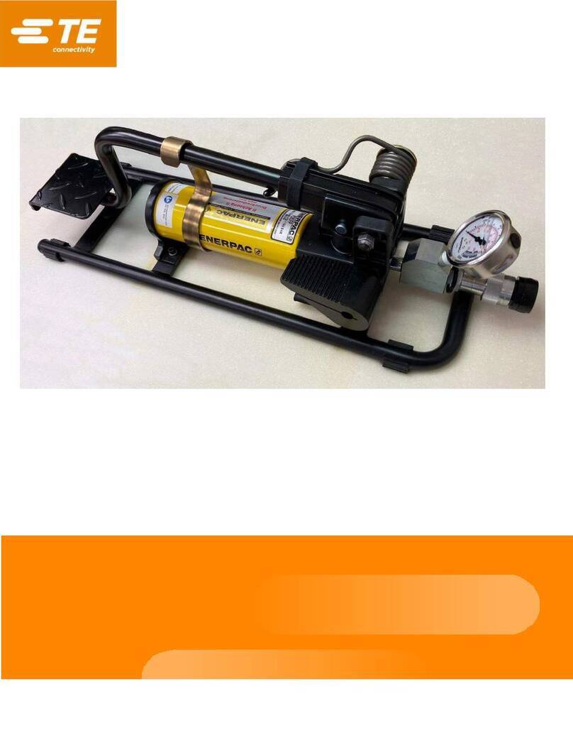
TE Connectivity Tyco 2063680-1 User manual

©2012 Tyco Electronics Corporation, a TE Connectivity Ltd. Company
All Rights Reserved
*Trademark
TE Connectivity, TE connectivity (logo), and TE (logo) are trademarks. Other logos, product and/or Company names may be trademarks of their respective owners.
Customer Manual
TOOLING ASSISTANCE CENTER
1-800-722-1111
This controlled document is subject to change.
For latest revision and Regional Customer Service,
visit our website at www.te.com
1of 10
LOC B
customer manual
409-10094
READ THIS FIRST!
. . . . . . . . . . . . . . . . . . . . . . . . . . . .2
Operating Manual for the Battery
Powered Hydraulic Pump Kit
2063680-1 05 JAN 12 Rev B
1. INTRODUCTION . . . . . . . . . . . . . . . . . . . . . . . . . . . . . . . . . . . . . . . . . . . . . . . . . . . . . . .3
2. DESCRIPTION . . . . . . . . . . . . . . . . . . . . . . . . . . . . . . . . . . . . . . . . . . . . . . . . . . . . . . . . .4
3. OPERATING PRECAUTIONS . . . . . . . . . . . . . . . . . . . . . . . . . . . . . . . . . . . . . . . . . . . . .5
3.1. Precautions for the Rechargeable Pump . . . . . . . . . . . . . . . . . . . . . . . . . . . . . . . . .5
3.2. Precautions for the Battery Cartridge and Pump. . . . . . . . . . . . . . . . . . . . . . . . . . . .5
3.3. Precautions for the Battery Cartridge . . . . . . . . . . . . . . . . . . . . . . . . . . . . . . . . . .. . 5
3.4. Precautions for the Battery Cartridge Charger . . . . . . . . . . . . . . . . . . . . . . . . . . .. . 5
4. OPERATION. . . . . . . . . . . . . . . . . . . . . . . . . . . . . . . . . . . . . . . . . . . . . . . . . . . . . . . . . . .6
4.1. Battery Charging Instructions . . . . . . . . . . . . . . . . . . . . . . . . . . . . . . . . . . . . . . . .. . 6
4.2. Attaching the Battery Cartridge. . . . . . . . . . . . . . . . . . . . . . . . . . . . . . . . . . . . . . .. . 6
4.3. Attaching the Hydraulic Hose . . . . . . . . . . . . . . . . . . . . . . . . . . . . . . . . . . . . . . . . . .7
4.4. Attaching the Remote Control Cord . . . . . . . . . . . . . . . . . . . . . . . . . . . . . . . . . . . . .7
4.5. Controlling the Pump (Figure 6) . . . . . . . . . . . . . . . . . . . . . . . . . . . . . . . . . . . . . . . .7
4.6. Guide to Crimping Capacity . . . . . . . . . . . . . . . . . . . . . . . . . . . . . . . . . . . . . . . . . . .8
5. MAINTENANCE AND INSPECTION . . . . . . . . . . . . . . . . . . . . . . . . . . . . . . . . . . . . . . . .8
5.1. Before Storing the Pump. . . . . . . . . . . . . . . . . . . . . . . . . . . . . . . . . . . . . . . . . . . . . . 8
5.2. Daily Maintenance. . . . . . . . . . . . . . . . . . . . . . . . . . . . . . . . . . . . . . . . . . . . . . . . . . .8
5.3. Semi-Annual Maintenance . . . . . . . . . . . . . . . . . . . . . . . . . . . . . . . . . . . . . . . . . . . . 9
5.4. Oil Leaks. . . . . . . . . . . . . . . . . . . . . . . . . . . . . . . . . . . . . . . . . . . . . . . . . . . . . . . . . .9
6. REPAIR/REPLACEMENT . . . . . . . . . . . . . . . . . . . . . . . . . . . . . . . . . . . . . . . . . . . . . . . .9
7. TROUBLESHOOTING . . . . . . . . . . . . . . . . . . . . . . . . . . . . . . . . . . . . . . . . . . . . . . . . . .10
8. REVISION SUMMARY. . . . . . . . . . . . . . . . . . . . . . . . . . . . . . . . . . . . . . . . . . . . . . . . . . 10
SAFETY PRECAUTIONS

409-10094
SAFETY PRECAUTIONS AVOID INJURY
Safeguards are designed into this application equipment to protect operators and maintenance personnel from
most hazards during equipment operation. However, certain safety precautions must be taken by the operator
and repair personnel to avoid personal injury, as well as damage to the equipment. For best results, application
equipment must be operated in a dry, dust-free environment. Do not operate equipment in a gaseous or
hazardous environment.
•Carefully observe the following safety precautions before and during operation of the equipment:
•ALWAYS wear appropriate ear protection.
•ALWAYS wear approved eye protection when operating powered equipment.
•ALWAYS keep guard(s) in place during normal operation.
•ALWAYS insert power plug into a properly grounded receptacle to avoid electrical shock.
•ALWAYS turn off the main power switch and disconnect electrical cord from the power source when
performing maintenance on the equipment.
•NEVER wear loose clothing or jewelry that may catch in moving parts of the application equipment.
•NEVER insert hands into installed application equipment.
•NEVER alter, modify, or misuse the application equipment.
TOOLING ASSISTANCE CENTER
CALL TOLL FREE 1-800-722-1111 (CONTINENTAL UNITED STATES AND PUERTO RICO ONLY)
The Tooling Assistance Center offers a means of providing technical assistance when required.
In addition, Field Service Specialists are available to provide assistance in the adjustment or repair of the
application equipment when problems arise which your maintenance personnel are unable to correct.
INFORMATION REQUIRED WHEN CONTACTING THE TOOLING ASSISTANCE CENTER
When calling the Tooling Assistance Center regarding service to equipment, it is suggested that a person familiar
with the device be present with a copy of the manual (and drawings) to receive instructions. Many difficulties can
be avoided in this manner.
When calling the Tooling Assistance Center, be ready with the following information:
1. Customer name
2. Customer address
3. Person to contact (name, title, telephone number, and extension)
4. Person calling
5. Equipment number (and serial number if applicable)
6. Product part number (and serial number if applicable)
7. Urgency of request
8. Nature of problem
9. Description of inoperative component(s)
10. Additional information/comments that may be helpful
2of 10
Rev B
DANGER
STOP

409-10094
3of 10
Rev B
Figure 1
1. INTRODUCTION
Battery Powered Pump 2063680-1 (Figure1) is a portable, battery-powered, hydraulic pump used to power
hydraulic hand tools.
The battery powered hydraulic pump kit comes complete with a 8,200 psi hydraulic pump and controller
(1804116-1); a battery charger (1804114-1); two nickel-cadmium battery cartridges (1804113-1); a 3/8 Inch
female screw type coupler (311471-1); and a metal storage box (1804115-1). The metal storage box is not
shown in Figure 1.
When reading this manual, pay particular attention to DANGER, CAUTION, NOTE statements.
DANGER
STOP
Denotes an imminent hazard which may result in moderate or severe injury.
!
CAUTION
Denotes a condition which may result in product or equipment damage.
NOTE
i
Highlights special or important information.
NOTE
i
Dimensions in this manual are in metric units [with U.S. customary units in brackets].

409-10094
4of 10
Rev B
2. DESCRIPTION
Refer to Figure 2.
BATTERY POWERED PUMP 2063681-1
Output . . . . . . . . . . . . . . . . . . . . . . . . . . . . . . . . . . . . . . . . . . . . . . . . . . . . . . . . . . . . . 8,200 psi
Drive Unit. . . . . . . . . . . . . . . . . . . . . . . . . . . . . . . . . . . . . . . . . . . . .For Single Acting Cylinders
Rated Voltage . . . . . . . . . . . . . . . . . . . . . . . . . . . . . . . . . . . . . . . . . . . . . . . .28.8V
Usage. . . . . . . . . . . . . . . . . . . . . . . . . . . . . . . . . . . . . . . . . . . . . . . . . . . Light Duty
Oil Delivery Pressure. . . . . . . . . . . . . . . . . . . . . . . . . . . . . . . . . . . . . . . . . . . . . . . . . .68.5 MPa
High Pressure Stage . . . . . . . . . . . . . . . . . . . . . . . . . . . . . . . . . . . . . . . . 0.31/min.
Low Pressure Stage. . . . . . . . . . . . . . . . . . . . . . . . . . . . . . . . . . . . . . . . . .1.81/min
Dimensions:. . . . . . . . . . . . . . . . . . . . . . . . . . . . . . . . . . .16 In. High x 6 In. Wide x 10 In. Deep
Weight: . . . . . . . . . . . . . . . . . . . . . . . . . . . . . . . . . . . . . . . . . . . . . . . 23 lbs (with two batteries)
Flow: . . . . . . . . . . . . . . . . . . . . . . . . . . . . . . . . . . . . . . . . . . . . . . . . . . . 108 Cu/In/Min@300psi
18 Cu/In/Min@8,200 psi
Fluid Reservoir Capacity . . . . . . . . . . . . . . . . . . . . . . . . . . . . . . . . . . . . . . . . . . . . . . . .61 Cu/In
BATTERY CARTRIDGE 1804113-1 (Standard)
Battery Type . . . . . . . . . . . . . . . . . . . . . . . . . . . . . . . . . . . . . . . . . . . . Sealed Nickel Cadmium
Voltage. . . . . . . . . . . . . . . . . . . . . . . . . . . . . . . . . . . . . . . . . . . . . . . . . . . . . . . . . . . . . . 14,4Vdc
Rated Current . . . . . . . . . . . . . . . . . . . . . . . . . . . . . . . . . . . . . . . . . . . . . . . . . . . . . . . . . 2.0 Ah
Charge Time . . . . . . . . . . . . . . . . . . . . . . . . . . . . . . . . . . . . . . . . . . . . . . . . . . . . . . .25 minutes
Dimension . . . . . . . . . . . . . . . . . . . . . . . . . . . . . . . . . . . . . . . . . . . . . . . . . . . . . . . . . . . . . . . . . .
3.5 In Long X 2.7 In. Wide X 5.3 In. High
Weight . . . . . . . . . . . . . . . . . . . . . . . . . . . . . . . . . . . . . . . . . . . . . . . . . . . . . . . . . . . .1.6 pounds
HIGH OUTPUT BATTERY CARTRIDGE 1804112-1 (Optional)
Battery Type . . . . . . . . . . . . . . . . . . . . . . . . . . . . . . . . . . . . . . . . Ni-mH (Nickel Metal Hydride)
Voltage. . . . . . . . . . . . . . . . . . . . . . . . . . . . . . . . . . . . . . . . . . . . . . . . . . . . . . . . . . . . . . 14,4Vdc
Rated Current . . . . . . . . . . . . . . . . . . . . . . . . . . . . . . . . . . . . . . . . . . . . . . . . . . . . . . . . . 2.9 Ah
Charge Time . . . . . . . . . . . . . . . . . . . . . . . . . . . . . . . . . . . . . . . . . . . . . . . . . . . . . . .45 minutes
Dimensions . . . . . . . . . . . . . . . . . . . . . . . . . . . . . . . . 3.5 In Long X 2.7 In. Wide X 5.3 In. High
Weight . . . . . . . . . . . . . . . . . . . . . . . . . . . . . . . . . . . . . . . . . . . . . . . . . . . . . . . . . . . .1.6 pounds
BATTERY CHARGER 1804114-1
Input Voltage . . . . . . . . . . . . . . . . . . . . . . . . . . . . . . . . . . . . . . . . . . . . . . 120 Vac Single Phase
Charging Capacity. . . . . . . . . . . . . . . . . . . . . . . . . . . . . . . . . . . . . . . . . . . . . . . . . . . . . . .20 VA
Dimensions . . . . . . . . . . . . . . . . . . . . . . . . . . . . . . . . 7.5 In Long X 4.5 In. Wide X 3.7 In. High
Weight . . . . . . . . . . . . . . . . . . . . . . . . . . . . . . . . . . . . . . . . . . . . . . . . . . . . . . . . . . . . 2 pounds
REPLACEMENT CONTROLLER 1804117-1. . . . . . . . . . . . . . . . . . . . . . . . . May be ordered separately
Figure 2

409-10094
5of 10
Rev B
3. OPERATING PRECAUTIONS
3.1. Precautions for the Rechargeable Pump
1. When connecting the coupler, be sure that no foreign objects are attached. If the coupler has become dirty,
clean it carefully before connecting it. Engaging the coupler when foreign objects are present will damage the
seals and lead to oil leakage from the connection.
2. Make sure that the coupler is securely connected. If the unit is pressurized while the coupler is not properly
connected, there will be damage to the seals or the crimp head.
3. Although a flexible hydraulic hose is used, do not bend it while pressure is being applied, or subject the
hose to shocks from metal objects. Either of these will shorten the working life of the hose and may result in
the hose bursting.
4. Never move the pump by pulling on the hydraulic hose or the remote control cords.
3.2. Precautions for the Battery Cartridge and Pump
1. To ensure smooth operation of the pump, always use the pump after it has been stored for at least one hour
at 10°C to 25°C. If the pump is stored for an extended period below -5°C, viscosity of the oil increases.
2. Allow the pump to cool 10 minutes after each 20 minutes of use. The pump was designed for light duty and
cannot be used continuously. Be sure that neither the motor or the oil become hot.
3. Check the hydraulic oil regularly. Replenish the oil when the level becomes low. Use the appropriate
hydraulic oil type.
4. The pump is a precision device and should not be dropped or subjected to shocks or other abuse.
3.3. Precautions for the Battery Cartridge
1. Do not short circuit the contacts or expose the cartridge to water, oil, or solvents.
2. Do not disassemble or attempt to repair the battery cartridge.
3. Do not dispose of the battery cartridge in a fire.
4. Do not drop or abuse the battery cartridge.
5. Do not leave the cartridge in an area where it will be exposed to temperatures greater than 140°F (60°C) for
an extended period.
6. The battery has a limited life. When the crimping capacity becomes about one half that of the original
capacity, the battery should be replaced.
7. If the battery is stored without being charged, natural drainage will cause the power to be reduced. The
battery should be completely re-charged every three months if not in use.
3.4. Precautions for the Battery Cartridge Charger
NOTE
i
This unit is for charging the battery cartridge in the pump kit only.
1. The LED indicator is green while the unit is charging the battery. The indicator turns an orange color when
the charging is completed.
2. Allow battery cartridges to cool completely before charging.
3. Allow at least 15 minutes between charges when charging several cartridges in succession.
4. Charge the batteries at an ambient temperature of 50°F to 95°F (10°C to 35°C). Charging time is
approximately 25 minutes for battery number 1804113-1; 45 minutes for battery number 1804112-1.
5. Never short circuit the output terminals.
6. Do not expose the charger to water, oil, or solvents.
7. Do not disassemble the charger, attempt to modify it, drop it, or otherwise abuse it.

409-10094
6of 10
Rev B
4. OPERATION
4.1. Battery Charging Instructions
1. Insert the plug end of the charger into a 120 Vac power source. The LED indicator on the charger will flash
red, indicating that the charger is in “stand by” mode and is ready to charge a battery.
CAUTION
!
DO NOT plug the charger into a generator. This will probably cause the fuse in the charger to “short,” and the charger
will not operate.
2. To charge a drained battery, insert the battery into the charger until the LED indicator registers a steady
green. This indicates the battery is being charged and will be completed in approximately 25 minutes.
The LED indicator will register orange when charging is complete.
3. Charge only appropriately cooled batteries. If the indicator registers a steady red color when the battery is
inserted, the battery is too hot to be charged and must be cooled to room temperature.
NOTE
i
Do NOT leave the batteryin the charger to cool. Thecharger will not recognize thatthe battery is already inserted andwill
fail to charge the battery.
4. Consult the Tooling Assistance Center at 1-800-722-1111 if the LED indicator goes out or is flashing “red.”
5. To recondition the battery, insert the battery into the charger and push the “R” button. The LED indicator
should flash green to indicate that the discharge cycle is in process.
NOTE
i
For technical questions or difficulty in operation, call the Tooling Assistance Center at 1-800-722-1111.
4.2. Attaching the Battery Cartridge
1. Pull out on the battery cartridges while pressing the latch. See Figure 3.
Latch
Pull Out On The
Battery Charger
Figure 3
To replace the two battery cartridges push them firmly back into place.
NOTE
i
Always install and use both battery cartridges at the same time.
2. After attaching the battery cartridges, check to see if they are in place by pulling them, without pressing the
latch.
Two battery cartridges must be inserted into the cartridge slots since they are connected “in series” to activate
a 28.8 Vdc motor.

409-10094
7of 10
Rev B
4.3. Attaching the Hydraulic Hose
1. Attach the male coupler of the hydraulic hose to the female coupler of the hydraulic pump as shown in
Figure 4.
Male Coupler of
the Hydraulic Hose No Gaps Coupler Ring
Female Coupler of the
Hydraulic Pump
Figure 4
2. Gently pull on the couplers to determine if they are securely connected. If the couplers are not engaged
properly, the ram will advance but will not retract.
3. Attach the application head to the opposite side of the hose (if it's not already attached).
4.4. Attaching the Remote Control Cord
Attach the remote control cord to the pump. Remove the cap from the receptacle at the pump. Then insert the
plug of the control cord and tighten the ring securely. The attached cord should resemble Figure 5.
Remote Control Cord
Plug of the Remote
Control Cord
Figure 5
4.5. Controlling the Pump (Figure 6)
1. To advance the piston, press and hold the “UP” button.
2. To retract the piston, press and hold the “DOWN” button.
3. When the hydraulic power reaches 8,200 psi, the motor shuts off and compression is complete.
“DOWN” Button
“UP” Button
Figure 6

409-10094
8of 10
Rev B
4.6. Guide to Crimping Capacity
This guide corresponds to battery cartridge number 1804113-1, only. In addition these figures are approximate
and can vary according to charging and crimping conditions.
When the crimping cycles are reduced to approximately 1/2 the normal cycle, this indicates that the battery life is
exhausted and the battery should be replaced a with a new one.
Each battery can be charged approximately 500 cycles.
For battery cartridge number 1804113-1:
— Cable size = 750 MCM
— Average Number of Crimping Cycles = 50 times
5. MAINTENANCE AND INSPECTION
5.1. Before Storing the Pump
Perform the following steps after the piston has reached it's lowest position.
1. Remove the battery cartridge.
2. Disconnect the plug of the remote control cord.
NOTE
i
Be sure that the cord does not become pulled, loose, or twisted.
3. Replace the receptacle cover.
4. Disconnect the coupler.
5. Re-attach the dust cap of the coupler to prevent dust from getting into the system.
5.2. Daily Maintenance
It is recommended that the pump be inspected daily by operating and maintenance personnel.
1. Check the hydraulic oil level and it's contaminationvisually through the oil gage. Add hydraulic oil if
appropriate.
2. If contamination of the oil is observed, replace the hydraulic oil completely (approximately one liter). Shell
T5 Hydraulic Oil is recommended.
3. When replacing the hydraulic oil, remove the air vent (refer to Figure 7).
Air Vent
Figure 7

409-10094
9of 10
Rev B
5.3. Semi-Annual Maintenance
Completely replace the hydraulic oil every six months. Shell T5 Hydraulic Oil is recommended.
CAUTION
!
NEVER use vegetable oil or brake oil with this pump.
If the tool is maintained regularly and correctly, it should provide trouble-free service. If a problem does occur,
contact the Tooling Assistance Center (see the bottom front page).
5.4. Oil Leaks
In most cases, it is possible to repair oil leaks using the method described below.
1. Remove the coupler at the point of the leak.
2. Carefully remove the sealing tape (PTFE tape) from the screw.
3. Wrap NEW sealing tape one and one half times around the screw head.
4. Begin wrapping the sealing tape 1mm to 2mm from the edge of the thread. See Figure 8.
Sealing Tape
1 mm to 2 mm
Figure 8
5. Tighten the coupler back into position. (The screw torque should be 29.4 - 48 Nm [3-5Kgf-cm2].)
NOTE
i
The pump is shipped with Shell T5 oil in the pump. Do NOT mix the oil. Always completely replace the oil if another type
of oil is used.
6. REPAIR/REPLACEMENT
If there are major problems with the battery powered pump, it should be returned to:
CUSTOMER SERVICE (038-035)
TYCO ELECTRONICS CORPORATION
PO BOX 3608
HARRISBURG PA 17105-3608
For customer repair service, call 1-800-526-5136.

409-10094
10 of 10
Rev B
7. TROUBLESHOOTING
1. Replace the battery before considering other causes.
a. Power to the pump is provided by the battery. Should a problem occur, the battery should be replaced.
b. Low battery power will not allow the pump to pressurize. The battery should be charged or replaced
before considering other causes.
2. Inspect the connection point to be sure that no leaking exists. The oil delivery of the pump is minimal, so
that even the slightest oil leak will effect performance.
3. Main causes of malfunction are as follows:
a. One of the pump's parts requires repair.
b. The hydraulic oil is contaminated. Replace the oil as described in Paragraph 5.2.
c. The strainer is clogged.
d. There has been mechanical wear.
NOTE
i
Althoughsomerepairs and replacements can be accomplished“on site,” itisrecommended that parts be shipped back to
TE Connectivity for repair/replacement. Refer to Section 6.
TROUBLESHOOTING GUIDE
PROBLEM CAUSE SOLUTION
Even when the “on” button is
pressed, nothing happens.
•Defective electrical supply
•Defective circuit board
•Remote control connection wire is
disconnected
Check the electrical connection.
Consult Tooling Assistance for repair service.
The pressure does not
increase. (No pressure is
measured at the head.)
•Battery failure
•Oil leaks from the joint
•Insufficient amounts of hydraulic oil
•Clogging of the strainer
•The pump mechanism is broken
1. Charge or replace the battery
2. Repair the oil leak and replenish hydraulic oil.
3. Overhaul the pump and remove the blockage.
4. Consult Tooling Assistance for repair service.
It takes a long time for the
piston to advance.
•Battery failure
•Oil is hot
•Oil leaks from the joint
•Insufficient amounts of hydraulic oil
•Air is trapped in the hose or head
•Pump mechanism is broken
1. Charge or replace the battery.
2. Allow pump to cool. Repair leak.
3. Replenish hydraulic oil.
4. Consult Tooling Assistance for repair service.
The piston does not retract to
its lowest position.
•Defective circuit board
•Remote control connection wire is
disconnected
•Pump mechanism is broken
Consult Tooling Assistance for repair service.
8. REVISION SUMMARY
•Removed misused trademark for PTFE.
•Updated document to corporate requirements.
Table of contents
Other TE Connectivity Water Pump manuals