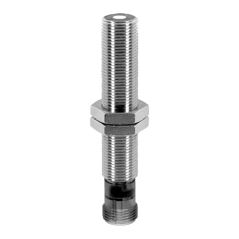
TE 85X1N Series User manual

TE CONNECTIVITY SENSORS/// MODEL 89X1N & 85X1N VIBRATION SENSOR
Ex rated doc ment, no changes allowed nless a thorized by Ex agency Page 1
20023687-24 Rev. A, 2022-11-07
IoT Wireless Vibration Sensor Installation Manual
LoRa & BLE
Environmental Information
Ambient Temperature -40 °C to + 60 °C
IP66/IP67
Models 85X1N eries
SUPPLY: 3.6 V / 4μA – 35mA
FCC ID: 2A85PA85X1N
IC: 29620-A85X1N
Models 89X1N eries
SUPPLY: 3.6 V / 4μA – 35mA
FCC ID: 2A85PA89X1N
IC: 29620-A89X1N
915MHz for US and 868MHz for EU
Explosive Atmospheres Designations for
Models 85X1N-EX and 89X1N-EX eries
U and Canada:
CSA22CA80098072X
IS CL I, DIV 1, GRP A, B, C, D, T4;
CL I, ZN 0, AEx ia IIC T4 Ga;
ATEX and IECEx:
EPS 21 ATEX 1 163 X
IECEx EPS 21.0053X
Ex II 1 G, Ex ia IIC T4 Ga;
•U Coverage
oANSI/UL 60079-0-2020
oANSI/UL 60079-11-2018
oANSI/UL 913-2019
oUL 61010-1, 3rd Edition (2012) + AMD1:2018
oFCC Certified
•Canadian Coverage
oCSA C22.2 No. 60079-0:19
oCAN/CSA C22.2 No. 60079-11:14
oCAN/CSA C22.2 No. 61010-1-12
+ Update No 1:2015 + Update No 2:2016 + AMD1:2018
oISED Certified
•European/IECEx Coverage
oIEC 60079-0:2017 Edition: 7.0
oIEC 60079-11:2011 Edition: 6.0
oIEC 61010-1:2010, IEC 61010-1:2010/AMD1:2016
oRED Compliant
•Radio Frequency Communication
oBl etooth® Q alified
oLoRaWAN Certified
CM

TE CONNECTIVITY SENSORS/// MODEL 89X1N & 85X1N VIBRATION SENSOR
Ex rated document, no changes allowed unless authorized by Ex agency Page 2
20023687-24 Rev. A, 2022-11-07
REVISION OF THE DOCUMENT
Release Date
Change Description Rev.
Prepared by Appr. ENG
11/07/2022 Initial release A

TE CONNECTIVITY SENSORS/// MODEL 89X1N & 85X1N VIBRATION SENSOR
Ex rated doc ment, no changes allowed nless a thorized by Ex agency
Page 3
20023687-24 Rev. A, 2022-11-07
LoRa + BLE Sensor Model Nu ber BLE Sensor Model Nu ber
WARNING & IMPORTANT SAFETY INSTRUCTIONS
This is the safety alert symbol. It is sed to alert yo to potential personal inj ry
hazards. Obey all safety messages that follow this symbol to avoid possible inj ry
or death.
DANGER indicates a hazardo s sit ation which, if not avoided,
will res lt in death or serio s inj ry.
WARNING indicates a hazardo s sit ation which, if not avoided,
co ld res lt in death or serio s inj ry.
CAUTION sed with the safety alert symbol, indicates a hazardo s
sit ation which, if not avoided, co ld res lt in minor or moderate
inj ry.
ELECTRICAL INSTALLATION (Raccorde ent électrique)
S itable for se in Class I, Division 1, Gro ps A, B, C and D Hazardo s Locations, or Non-Hazardo s
locations only.
(AVERTI EMENT) Uniq ement adapté à n sage dans les Zones dangere ses de la classe 1, division 1 des
gro pes A, B, C, et D ainsi q e dans les zones non dangere ses.
EXPLOSION HAZARD: S bstit tion of components may impair s itability for Class I Division 1
(AVERTI EMENT)
Risq e d’explosion - Remplacement d’ n composant pe t empêcher la conformité de Classe I, Division 1.
POTENTIAL ELECTROSTATIC CHARGING HAZARD – SEE SPECIFIC CONDITIONS OF USE IN
INSTRUCTIONS.
(AVERTI EMENT) DÉCHARGE POTENTIEL ÉLECTROSTATIGUE HAZARD- VOIR LES INSTRUCTIONS

TE CONNECTIVITY SENSORS/// MODEL 89X1N & 85X1N VIBRATION SENSOR
Ex rated document, no changes allowed unless authorized by Ex agency Page 4
20023687-24 Rev. A, 2022-11-07
To prevent ignition of flammable or combustible atmospheres, read, understand and adhere to the
manufacturer's live maintenance procedures.
(AVERTISSEMENT) Pour éviter l'inflammation des atmosphères inflammables ou combustibles, lisez, comprenez et
respectez les procédures de maintenance en direct du fabricant.
Discontinue operation of sensor if plastic housing is broken, deformed or absent, ensure S/N match
between sensor and plastic housing
(AVERTISSEMENT) Arrêtez le fonctionnement du capteur si le boîtier en plastique est cassé, déformé ou absent,
assurez-vous que le numéro de série correspond entre le capteur et le boîtier en plastique.
FOR MODEL 85X1N AND 89X1N SERIES
USE ONLY SAFT (LI-SOCl
2
) LS17330. Do not attempt to open,
service or disassemble the battery, Do not short circuit. It may explode if disposed of in fire.
(AVERTISSEMENT) POUR LES MODÈLES DE LA SÉRIE 85X1N ET 89X1N
UTILISEZ UNIQUEMENT DES PILES
SAFT (LI-SOCl
2
) LS17330. N'essayez pas d'ouvrir, de réparer ou de démonter la batterie. Ne court-circuitez pas. Il peut
exploser s'il est jeté au feu.
Conditions for Safe Use
i. The non-metallic parts incorporated in the enclosure may generate an ignition-capable level of
electrostatic charge. Upon installation, care shall be taken to avoid location where the external conditions
are conductive to the build-up of electrostatic charge on such surfaces. Additionally, the equipment shall
only be cleaned with a damp cloth.
ii. The vibration sensor does not have an Earth ground terminal. The vibration sensor shall be Earth
grounded as part of the final installation.
iii. Use only 3.6 V SAFT battery LS17330 Primary lithium-thionyl chloride (Li-SOCL2)2/3 A-size bobbin cell.
iv. The battery should be installed or replaced only in non-hazardous areas.

TE CONNECTIVITY SENSORS/// MODEL 89X1N & 85X1N VIBRATION SENSOR
Ex rated doc ment, no changes allowed nless a thorized by Ex agency
Page 5
20023687-24 Rev. A, 2022-11-07
BATTERY INSTALLATION AND REPLACEMENT
Remove the cover
Hold the sensor firmly by the hex area at the bottom. Rotate the top cover co nter-clockwise from the locked
index mark on the cover to the nlocked mark. Caref lly lift the cover off in a straight direction to avoid
damage to internal components.
Avoid to ching any portion of the PC boards or electronic components.
Insert the battery
Follow these steps:
•
P sh the battery removal strip into the battery compartment so the new battery will sit on top of it.
•
Hold the battery spacer so the narrow end covers the negative (-) battery contact electrode (nearer
to the hex end of the device).
•
Insert the battery (negative end first) so it traps the spacer between the negative battery contact and
the negative electrode on the battery.
•
Slowly p sh the positive electrode end of the battery into the battery compartment ntil it’s f lly
seated.
•
Holding the battery in place, slowly extract the spacer from the negative electrode.
•
A one second flash from the LED will indicate that the battery has been inserted properly.
Unlock direction (CCW)
Spacer
Battery Compartment
Positive (+)
Negative (-)

TE CONNECTIVITY SENSORS/// MODEL 89X1N & 85X1N VIBRATION SENSOR
Ex rated doc ment, no changes allowed nless a thorized by Ex agency
Page 6
20023687-24 Rev. A, 2022-11-07
Remove the Battery
Remove the battery by p lling the battery removal strip. Be caref l to avoid to ching or holding the device
aro nd the PC boards and electronic components.
Reinstall the cover
•
Orient the cover so the unlock index mark aligns with tab at the base of the sensor.
•
Slide the cover down so it fits tightly against the O-ring seal above the hex.
•
Rotate the cover clockwise until the locked index mark aligns with the position of the base tab.
Caution:
The Cover is tightly matched with Base/O-ring, so some resistance might be felt on rotation.
Index tab
Unlock Index Mark
Lock direction (CW)

TE CONNECTIVITY SENSORS/// MODEL 89X1N & 85X1N VIBRATION SENSOR
Ex rated doc ment, no changes allowed nless a thorized by Ex agency
Page
7
20023687-24 Rev. A, 2022-10-14
SENSOR MOUNTING
The vibration sensor should be stud mounted on a clean, flat surface. The correct mounting torque for the sensor
is 2.2 to 2.9 lb-ft (3 to 4 N-m). It is recommended to put a small amount of silicon grease on the bottom of the
vibration sensor before mounting. This provides better coupling of vibration signals into the sensor.
WARNING – Do NOT tighten the sensor by twisting on the housing. Damage to the sensor WILL occur. Tighten to
the correct torque using a wrench on the hex base.
MOUNTING METHOD & ACCESSORIES
Shown below is a special mounting options available for the 8931N/8531N triaxial sensor. It consists of three
machine parts to build one adaptor. This allows the 8931N/8531N sensors to be rotated in order to align the X
and Y axes in the desired direction.
Open end wrench size: 1-7/16in or 36mm
8X31 Adjustable Angle Mounting Block
20027468-00
Sensor Hex Base

TE CONNECTIVITY SENSORS/// MODEL 89X1N & 85X1N VIBRATION SENSOR
Ex rated doc ment, no changes allowed nless a thorized by Ex agency
Page
8
20023687-24 Rev. A, 2022-10-14
A solid mounting method is required to get optimum performance from the sensor. Any loose parts or unsecured
mounting features will introduce noise and corrupt the signals of interest. Shown below are six different mounting
options available for the 89X1N/85X1N sensor.
For the adhesive mo nting st d, sec re with a rigid adhesive s ch as epoxy or cyanoacrylate. Do not se
press re sensitive adhesives or foam tapes. For the magnetic mo nting st d, remove the keeper prior to
attachment. The magnetic mo nting will have a 30 lb p ll strength when attached to a ferro s s rface.
Impact energy level code: IK05

TE CONNECTIVITY SENSORS/// MODEL 89X1N & 85X1N VIBRATION SENSOR
Ex rated doc ment, no changes allowed nless a thorized by Ex agency
Page
9
20023687-24 Rev. A, 2022-10-14
20023687-20 Installation Drawing

TE CONNECTIVITY SENSORS/// MODEL 89X1N & 85X1N VIBRATION SENSOR
Ex rated doc ment, no changes allowed nless a thorized by Ex agency
Page
10
20023687-24 Rev. A, 2022-10-14
Additional Notes:
• For more prod ct information please refer to o r website: www.te.com
• It is recommended to remove the battery if the sensor is not in se.
te.com/sensors
The Bluetooth® word mark and logos are registered trademarks owned by the Bluetooth SIG, Inc. and any use of such
marks by TE Connectivity is under license. Other trademarks and
trade names are those of their respective owners.
Measurement Specialties Inc., a TE Connectivity company.
Measurement Specialties (MEAS), American Sensor Technologies (AST), TE Connectivity, TE Connectivity (logo) and
EVERY CONNECTION COUNTS are trademarks. All other logos,
products and/or company names referred to herein might be trademarks of their respective owners.
The information given herein, including drawings, illustrations and schematics which are intended for illustration purposes
only, is believed to be reliable. However, TE Connectivity makes
no warranties as to its accuracy or completeness and disclaims any liability in connection with its use. TE Connectivity‘s
obligations shall only be as set forth in TE Connectivity‘s Standard
Terms and Conditions of Sale for this product and in no case will TE Connectivity be liable for any incidental, indirect or
consequential damages arising out of the sale, resale, use or misuse of the product. Users of TE Connectivity products
should make their own evaluation to determine the suitability of each such product for the specific application.
© 2022 TE Connectivity Ltd. family of companies All Rights Reserved.
This manual suits for next models
1
Table of contents
Popular Accessories manuals by other brands
Auzone
Auzone Pro-Sensor manual
aldes
aldes CONNECT BOX Assembly instructions

Sennheiser
Sennheiser Fluesterstimmenverstaerker Gebrauchsanleitung
BEA
BEA COLIBRI ONE DRO quick start guide
PCB Piezotronics
PCB Piezotronics PCB-HT(M)354C02 Installation and operating manual

Beurer
Beurer LA 40 Instructions for use
