OTT ecoN User manual

Operating instructions
UV Nitrate Sensor
OTT ecoN
English

Technische Änderungen vorbehalten!

Contents
1 Scope of supply 5
2 Order numbers and version code 5
3 Basic safety instructions 7
4 ntroduction 8
5 nstalling the OTT ecoN 10
5.1 Installing in an observation well 11
5.2 Installing with fastening clamps 12
5.3 Installing on a float 13
5.4 Electrical connection 14
6 Setting the operating parameters 15
6.1 onnecting the OTT ecoN to a P 15
6.2 alling up the OTT ecoN web interface 16
7 Modbus protocol (RTU) 18
7.1 Prerequisites 18
7.2 "Read Holding Registers" (0x03) / "Write Multiple Register" (0x10) functions 18
7.3 "Write Single Registers" function (0x06) 19
7.4 "Report Server ID" function (0x11) 19
8 Maintenance 20
8.1 leaning the OTT ecoN 20
8.2 hecking the OTT ecoN zero point 21
8.3 alibrating the OTT ecoN 22
8.4 hecking OTT ecoN reference values 23
9 Repairs 24
10 Notes about the disposal of old units 24
11 Technical data 25
12 Measuring range, limits, accuracy depending on path length 26
Appendix A – Dimensions 27
Appendix B – Accessories: Mechanical wiper 28
B1 – Preparing the mechanical wiper 29
B2 – Installing the mechanical wiper on the OTT ecoN 31
B3 – Electrically connecting the mechanical wiper 31
B4 – hanging the wiper blade 33
B5 – Mechanical wiper technical data 34
Appendix C – Note on Declaration of Conformity 35
3

4

5
1 Scope of supply
– 1 Optical UV nitrate sensor (immersion housing),
Housing material: stainless steel;
Permanently attached connecting cable with M12-connector*, 10 metres;
Serial interface: RS-485 with Modbus transmission protocol
– 1 onnecting cable with M12-socket* and open ends; 1.5 metres
– 1 alibration certificate
2 Order numbers and version code
OTT ecoN UV Nirate Sensor 63.300.001.9.0
with path length (measuring range):
– 0.3 mm –.3
– 1 mm –1
– 2 mm –2
– 5 mm –5
– 10 mm –10
Accessories Mechanical wiper 63.300.010.9.0
– For cleaning the optical path
– Without wiper shaft and wiper blades
– For mounting on the OTT ecoN housing tube
– Permanently attached connecting cable with M8-connector*; 10 metres
– onnecting cable with M8-socket* and open ends; 1.5 metres
Extension cable for OTT ecoN
M12-socket/M12-connector*
– 10 metres 63.300.018.9.0
– 25 metres 63.300.019.9.0
Extension cable for mechanical wiper
M8-socket/M8-connector*
– 10 metres 63.300.016.9.0
– 25 metres 63.300.017.9.0
Connecting cable with open ends
for OTT ecoN 63.300.035.9.0
with M12-socket*; 1.5 metres
Connecting cable with open ends
for mechanical wiper 63.300.036.9.0
with M8-socket*; 1.5 metres
Fastening clips for OTT ecoN 63.300.031.9.0
66 mm x 86 mm; black; including mounting accessories
Float for OTT ecoN 63.300.030.9.0
for horizontal installation in surface waters with
fluctuating water level (alternative to fixed,
suspended vertical installation)
* The M12/M8 connectors are not pressure water tight ➝not suitable for use under water!
Protection: IP67
OTT ecoN

VALtub
Plastic shell for checking the zero point
– 10 mm 63.300.032.9.0
– 50 mm 63.300.033.9.0
G2 nterface Box
for configuring the OTT ecoN via a local network
(LAN, Local Area Network); Ethernet interface (RJ45 socket);
optional WLAN; OTT ecoN connection via M12 socket
– with WLAN connection 63.300.020.9.0
– without WLAN connection 63.300.021.9.0
Operating instructions
– German 63.300.001.B.D
– English 63.300.001.B.E
– French 63.300.001.B.F
– Spanish 63.300.001.B.S
Set of wiper blades (5 pcs.)
including compatible wiper shaft, mounting accessories,
lubricating grease and tool
– for 1 mm path length 63.300.011.9.0
– for 2 mm path length 63.300.012.9.0
– for 5 mm path length 63.300.013.9.0
– for 10 mm path length 63.300.014.9.0
Optical cleaning set 63.300.034.9.0
– Dropper bottle with acetone
– leaning wipes for optical lenses, 50 pcs.
– Plastic pliers
Spare parts/
consumables
6

3 Basic safety instructions
Read these operating instructions before commissioning the OTT ecoN. Ensure
you are thoroughly familiar with how to install and operate the OTT ecoN.
Retain these operating instructions for subsequent reference.
The OTT ecoN is used for continuous measurement of the nitrate content of ground
and surface water. Measurement in water with a salt content of > 1 PSU is not
possible. Only use the OTT ecoN as described in these operating instructions. For
further information ➝ see hapter 4, Introduction.
Observe all detailed safety instructions specified for the individual work steps.
All safety instructions provided here are indicated by a warning symbol placed
next to them.
Note that the OTT ecoN may only be installed by a trained specialist
(e.g. electrician).
For further information ➝ see hapter 5, Installing the OTT ecoN.
Ensure compliance with the electrical, mechanical and climatic specifications set
out in the technical data.
For further information ➝ see hapter 11, Technical Data.
Do not make any changes or modifications to the OTT ecoN. hanges or modifi-
cations invalidate all warranty entitlements. In addition, the radio approval neces-
sary for operation is invalidated.
Only have a defective OTT ecoN inspected and repaired by our repair centre
Never repair it yourself.
For further information ➝ see hapter 9, Repairs.
After decommissioning, dispose of the OTT ecoN properly. Never dispose of
the OTT ecoN with normal household waste.
For further information ➝ see hapter 10, Instructions for disposal of used
equipment.
7

4 ntroduction
The OTT ecoN is a measuring instrument for continuous determination of the
nitrate content of ground and surface water.
The following nitrate concentrations in water can be determined:
NO3-N
NO3
NOX-N 1) (calibrated with standard NO3solution)
NOX1) (calibrated with standard NO3solution)
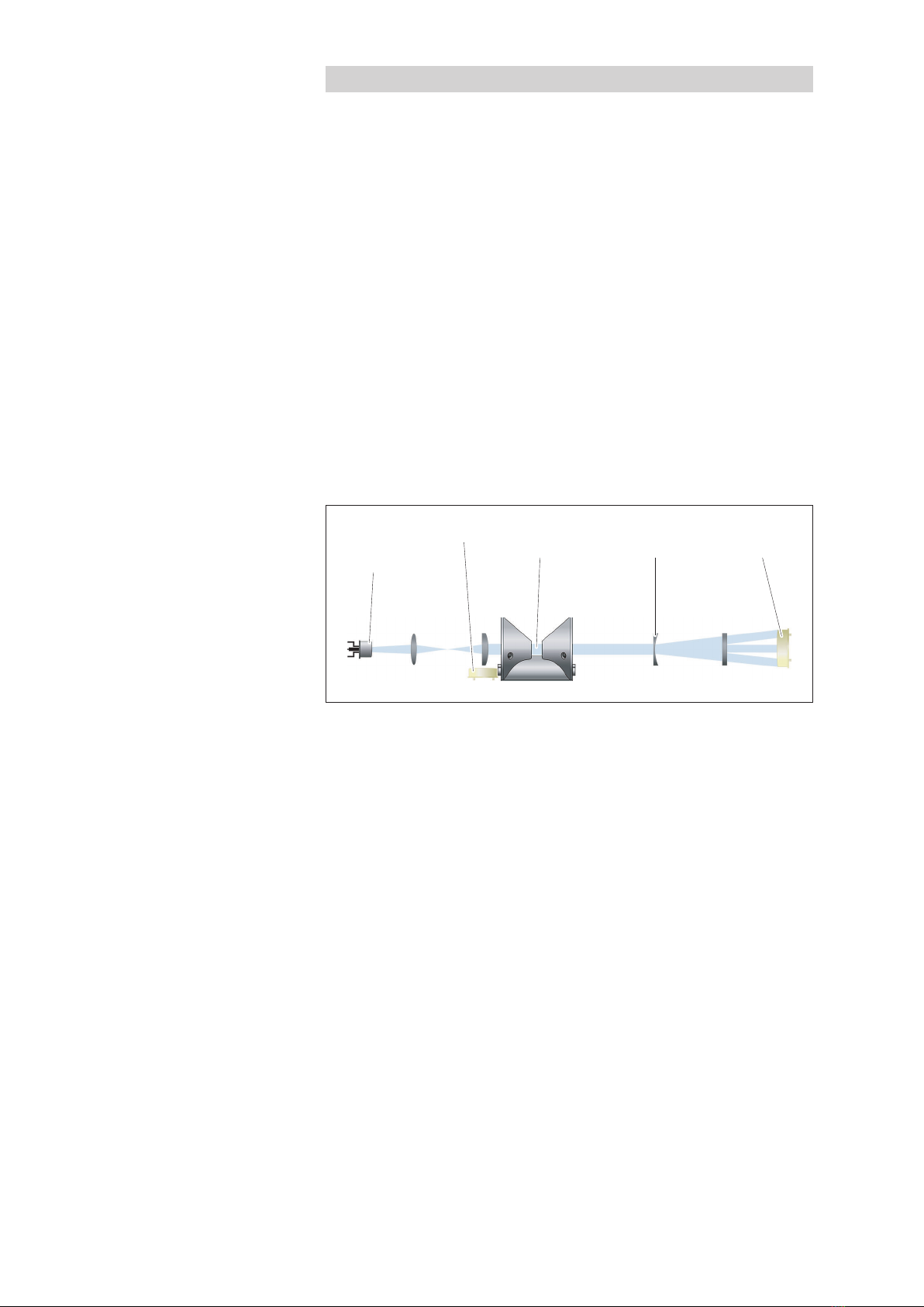
Figure 1 provides a schematic illustration of the measuring principle: A Xenon
flash lamp acts as a broad band light source. The light beam first passes through
an initial lens system, then passes through the measuring medium (water) in the
optical path, followed by a second lens system and is then received by three
detectors, which are photo diodes equipped with wavelength-specific filters. The
light beam at a wavelength of 212 nm is attenuated according to the nitrate con-
tent in the measuring medium. A reference diode before the optical path deter-
mines the unattenuated light output. This compensates for a fluctuating or deterio-
rating light source output. The additional attenuations measured at wavelengths of
254 nm and 360 nm also enable the OTT ecoN to compensate for organic inter-
ference or turbidity of the water.
To cover a nitrate measuring range of 0 to almost 900 mg/L with high precision
and resolution, the OTT ecoN is available with six different optical path lengths
(= measuring ranges; 0.3 - 10 mm).
The electrical connection to a data logger or a controller is via the permanently
installed connecting cable with M12 industrial connector. An RS-485 interface
with Modbus (RTU) transmission protocol is available for this purpose.
The nitrate sensor is equipped with an integrated web interface for setting the
operating parameters on the OTT ecoN. To use this, the OTT ecoN must be tem-
porarily connected to a P using an interface box. Any internet browser can be
used as the user interface.
The measuring windows are equipped with anti-fouling technology with nano-coat-
ed glass keeping the windows largely free of dirt deposits. At problematic measur-
ing points with high organic interference, the nitrate sensor can also be fitted with a
mechanical wiper. The wiping movements can be set to any time interval (externally
controlled).
1) ombined value for nitrate and nitrite, where both nitrate and nitrite are present in the water to be
measured. Differentiation between nitrate and nitrite is not possible with the OTT ecoN. The combined
values can be internally scaled using a factor if required.
Fig. 1: Optical measuring principle of the
OTT ecoN UV Nitrate Sensor.
Light source
(Xenon-
flash light)
Reference diode Optical
path
Optical
lenses
Detectors
(3 x)
8

9
The OTT ecoN can be installed in different ways: Suspension in an observation well,
attached to a suitable substrate with fastening clips or attached to a float.
Maintenance work, cleaning, zero point checking and checking the reference values
/ quality index can be carried out by support staff themselves. The nitrate sensor can
be calibrated either in the factory by the OTT repair centre or by trained specialist
personnel with the appropriate equipment.
Optical path
Housing tube
(top)
Housing tube
(bottom)
Measuring window
Mounting rod
Shackle
Connecting cable
Fig. 2: Overview of
OTT ecoN UV Nitrate Sensor.

5 nstalling the OTT ecoN
The OTT ecoN can be installed in three different ways depending on the specific
application:
suspended in an observation well see 5.1
attached to a suitable substrate with fastening clips see 5.2
attached to a float see 5.3
With all installation types, note the following:
the optical path must always be completely under water;
there must be an unobstructed inflow of water in the optical path;
the inflow direction should be at right-angles to the optical path (see Figure 3);
the connecting cable may not be used for attaching or suspension; it may not
be subjected to any mechanical load in addition to its own weight!
contact between the sensor and the ground is to be avoided; risk of damage.
installation should be carried out in such a way that the OTT ecoN can be tem-
porarily uninstalled for maintenance without excessive work;
the measuring windows must be completely free of air bubbles after immersion;
the salt content of the water to be measured may not exceed 1 PSU 1)
➝no measurement is possible in seawater, brackish water, mining waste water
with a high salt content, ... .
1) 1,77 mS/cm at 20 °
Fig. 3: Inflow direction.
10

5.1 nstalling in an observation well
Suspend the OTT ecoN on a non-corroding chain or a stainless steel cable. To
do this, attach the chain/cable to the mounting rod with a shackle.
Suspend the connecting cable on the chain/cable with an ISO anchor clamp or
with cable ties.
Recommended minimum diameter of observation well: 4 inches.
Fig 4: Suspending the OTT ecoN
in an observation well.
11

5.2 nstalling with fastening clamps
Attach the OTT ecoN to a suitable substrate with fastening clips and the
enclosed installation accessories (see "Accessories"). Attach the fastening clips
as closely as possible to the ends of the sensors. The substrate should be non-
corroding.
Attach the connecting cable with cable clamps or install in a cable duct.
Fig. 5: Installing the OTT ecoN
with fastening clamps.
12

5.3 nstalling on a float
This is the preferred installation type for surface water with significant fluctuations
in the water level
Attach the OTT ecoN to the float (see "Accessories") as shown in Figure 6.
Attach the fastening clamps as closely as possible to the ends of the sensors.
Secure the float against drifting with non-corroding chains or stainless steel
cables.
Attach the connecting cable to the chain/cable with cable ties.
Fig. 6: Installing the OTT ecoN on a float.
13

5.4 Electrical connection
Supply voltage + 12 … + 24 VD (±10 %)
Power consumption max. 7 W
Notes:
Before electrical connection to a data logger/controller, the OTT ecoN
operating parameters must be set; see hapter 6.
Do not shorten the OTT ecoN connecting cable or remove the M12 connector.
onnect using the connecting cable with open ends and M12 socket (see
"Accessories").
For cable lengths > 10 meters (with extension cable), the supply voltage
must be + 24 VD (voltage drop).
Risk of damage to the OTT ecoN
The supply voltage must be connected with the correct polarity. heck this
before applying the supply voltage.
onnect the connecting cable with open ends (M12 socket) to the OTT ecoN
connecting cable (M12 connector). Please note: The M12 industrial connectors
are not pressure water tight ➝Not suitable for use under water (degree of pro-
tection: IP 67).
onnect the red wire to the supply voltage (+12 … 24 VD ).
onnect the blue wire to earth (GND).
onnect the brown wire to the RS-485 (B) interface on a Modbus master.
onnect the white wire to the RS-485 (A) interface on a Modbus master.
If required: connect braided shield.
With electrically isolated OTT ecoN and Modbus master voltage supplies: Also
loop the earth (GND) connection through to the RS-485 interface.
The OTT ecoN is ready to operate as soon as the supply voltage is switched on.
Note: When connecting an OTT ecoN that is not continuously supplied with
voltage to an OTT netDL, a boot up time of 90 seconds is required!
Fig. 7: Wire assignment in connecting
cable with open ends.
Connecting cable
red +12 … +27 V
DC
blue GND
brown RS-485 D+ (B)
white RS-485 D– (A)
not used
Braided shield
14

6 Setting the operating parameters
The sensor is equipped with an integrated web interface for setting the operating
parameters on the OTT ecoN. To use this, the OTT ecoN must be temporarily con-
nected to a P using an interface box (see "Accessories"). Any internet browser
can be used as the user interface.
6.1 Connecting the OTT ecoN to a PC
Required accessories:
Power adapter 1)
RJ45 patch cable (Ethernet cable) 1)
G2 interface box
1) included with the G2 interface box
Note: When setting the operating parameters, the voltage supply to the
OTT ecoN comes from the G2 interface box.
onnect the M12 connector on the OTT ecoN connecting cable to the G2 inter-
face box.
onnect the power adapter to the G2 interface box and plug into a mains outlet.
Wait for 3 seconds.
onnect the G2 interface box to a free Ethernet port (RJ45 socket) on a P
using the RJ45 patch cable. (Alternatively, connection using an Ethernet switch
or router with DH P server is possible.)
Fig. 8: onnecting the OTT ecoN to a P .
15

6.2 Calling up the OTT ecoN web interface
Note: The Ethernet interface on the P must be configured to automatically obtain
the required network settings (DH P protocol).
Start any internet browser on the P .
In the browser, enter one of the following:
– http://ecoN.ott/
– http://ecoN_serial number/
– http://192.168.77.1/
and press enter ➝The home page of the OTT ecoN user interface opens (in
English).
Web interface menu structure
"Overview"
– Information about the OTT ecoN
– Information about the Xenon flash lamp
" alibration"
– This function is reserved exclusively for OTT service personnel or specially
trained users; "Login" and "Password" required
"Data Logger"
– Simple, internal data logger;
the sample/storage interval is 30 seconds;
– " lear" clears and formats the internal memory
– "Download" copies the measured values recorded in the selected period
("Start date" to "End date") to the P
"Measurement"
–"Parameter": shows the measured results from the last measurement in a table
– "Measure now!": starts instantaneous value measurement
– "Settings": allows you to enter an offset value and scaling factor and to
calculate a sliding mean value over "n" measured values
– "Edit"
" omment": enter any informative comments
"Automatic": activates/deactivates automatic measurement (must be activated
in combination with an OTT netDL or Sutron datalogger!)
"Interval [s]": sample/storage interval is 30 seconds;
"Pheripherals"
– RS-485 interface parameters; factory default setting: "Modbus RTU", "9600",
"none", "none", "1";
– "Address": Modbus address; factory default setting: "1"
Fig. 9: OTT ecoN user interface.
16

"System"
– " ommon Settings", "Description": e.g. station name/description
– " urrent Date and Time": internal date and time on the OTT ecoN
– "Recovery Point": this function is reserved exclusively for OTT service person-
nel or specially trained users; "login"/"password" required
– "System Log": Log file containing measurements performed, changes to the
operating parameters and error messages. "Download!" copies the log file to
the P .
Explanations of reference measured values
"Measurement" | "Parameter" function
SQ Sensor-Quality-Index, specifies the quality of a measurement:
1,0 … 0,8 ➝OK
0,8 … 0,5 ➝Marginal
< 0,5 ➝Error, see hapter 8.4
RefA Light intensity on the 212 nm channel; this value should always be
higher than 150, otherwise insufficient light reaches the specific detector.
RefB Light intensity on the 254 nm channel; this value should always be
higher than 150, otherwise insufficient light reaches the specific detector.
RefC Light intensity on the 360 nm channel; this value should always be
higher than 150, otherwise insufficient light reaches the specific detector.
RefD specifies the light intensity of the Xenon flash lamp; this value should
always be higher than 13 000.
For further information on evaluating the reference measured values,
see hapter 8.4.
17

7 Modbus protocol (RTU)
7.1 Prerequisites
onnection via RS-485 interface
Transmission parameters data bits: 8; parity: none; stop bits: 1 (8N1)
Transmission speed 9600 bps
Operating parameter "Measurement |"Automatic" ombined with OTT netDL: activated
Note: When connecting the OTT ecoN to an IP Datalogger OTT netDL, the OTT netDL configuration is limited on using
Modbus function "Read Holding Registers" (0x03).
7.2 "Read Holding Registers" (0x03) / "Write Multiple Register" (0x10) functions
1) Byte sequence: AB D (Big Endian)
Register name
Register-
number Type Value range
Factory
setting
Access-
mode Unit
Bus address 0000 unsigned word 1 … 247 1 R/W –
Serial number 0010 unsigned word 10 Byte; AS II-Format – R –
Firmware version 0015 unsigned word 10 Byte; AS II-Format – R –
Measured value
NO3-N
scaled value
1000
1500
float 1) 1 mm: 0.5 … 60
10 mm: 0.05 … 6
R [mg/L]
Measured value NO3
scaled value
1002
1502
float 1) 1 mm: 2.2 … 266
10 mm: 0.22 … 26.6
R [mg/L]
Spectral quality
index SQI
scaled value
1004
1504
float 1) 0 … 28000 R [1]
Light intensity
212 nm; RefA
scaled value
1006
1506
float 1) 0 … 28000 R [1]
Light intensity
254 nm; RefB
scaled value
1008
1508
float 1) 0 … 28000 R [1]
Light intensity
360 nm; Ref
scaled value
1010
1510
float 1) 0 … 28000 R [1]
Light intensity
reference diode, RefD
scaled value
1012
1512
float 1) 0 … 28000 R [1]
18

7.3 "Write Single Registers" function (0x06)
Writing the value "0x0101" into the register "0x0001" starts a single measure-
ment. Afterwards the measured values can be read out via function "Read
Holding Registers".
7.4 "Report Server D" function (0x11)
This function outputs the sensor name, the serial number and the firmware version
each "null terminated".
19

8 Maintenance
8.1 Cleaning the OTT ecoN
Recommended interval: every 12 months
With problematic local measuring point conditions
(organic interference or water turbidity):
Every 4 to 6 months as required. Tip: After initial instal-
lation, check the sensor at short intervals and adjust the
cleaning interval according to specific requirements.
Required equipment: soft brush, sponge
mild soap solution
if required: itric /acetic acid solution (10 %)
if required: Oxalic /ascorbic acid solution (5 %)
lint free cloth / paper cloth / optical wipe
Acetone
Ultra pure water
Risk of damage to the OTT ecoN
Do not use any chemicals other than those specified here.
Do not use abrasive cleaning agents or objects.
lean the measuring window with the utmost care.
Protect the M12 socket on the connecting cable from moisture!
CAUT ON Risk of injury to the skin/eyes/respiratory system due to acetone
and acids
Improper handling of acetone and acid can lead to minor to moderately
severe injuries, particularly damage to
– Skin: Dryness (acetone: degreasing effect) skin changes, skin damage,
chemical burns;
– Eyes: ornea damage, irritation, chemical burns;
– Respiratory system (inhalation): Irritation, fatigue, headaches, dizziness, nau-
sea/vomiting, acetone in higher doses has an anaesthetic effect
Wear laboratory gloves and protective goggles to perform cleaning.
Ensure adequate ventilation and do not inhale acetone vapour!
Uninstall the OTT ecoN.
lear adherent dirt: Soak the OTT ecoN in a mild soap solution for several
hours.
If required: Remove any residual dirt with a soft sponge or brush.
For lime scale deposits: Place the OTT ecoN in a 10 % citric acid or acetic acid
solution for approx. 15 ... 30 minutes.
For brown deposits (iron or manganese oxide): Place the OTT ecoN in a 5 %
oxalic acid or 10 % ascorbic acid solution for approx. 15 ... 30 minutes.
Thoroughly rinse the OTT ecoN with tap water.
lean the measuring windows: Soak a lint free cloth/paper cloth/special opti-
cal wipe with a few drops of acetone (see "Accessories") and carefully wipe off
both measuring windows; see Figure 10.
20
Table of contents
Other OTT Accessories manuals