TE TECP-90-703 User manual
300001749244 Rev A Page 1
© 2012 Tyco Electronics Corporation. All Rights Reserved.
INTRODUCTION .............................................................................1
1 PRODUCT DESCRIPTION ..................................................................2
2 MAIN COMPONENTS .....................................................................3
3 GROUNDING AND BONDING THE CHASSIS ......................................................4
4 CHASSIS INSTALLATION PROCEDURE .........................................................4
5 DOOR INSTALLATION AND OPERATION ........................................................6
6 WHERE TO FIND OTHER INFORMATION ........................................................8
6.1 Adapter Pack and Module Installation Instructions ...........................................8
6.2 Routing of Cables, Fibers, and Patch Cords................................................8
6.3 Phone Numbers, Mail Address, Email Address, and Product Portal ...............................8
INTRODUCTION
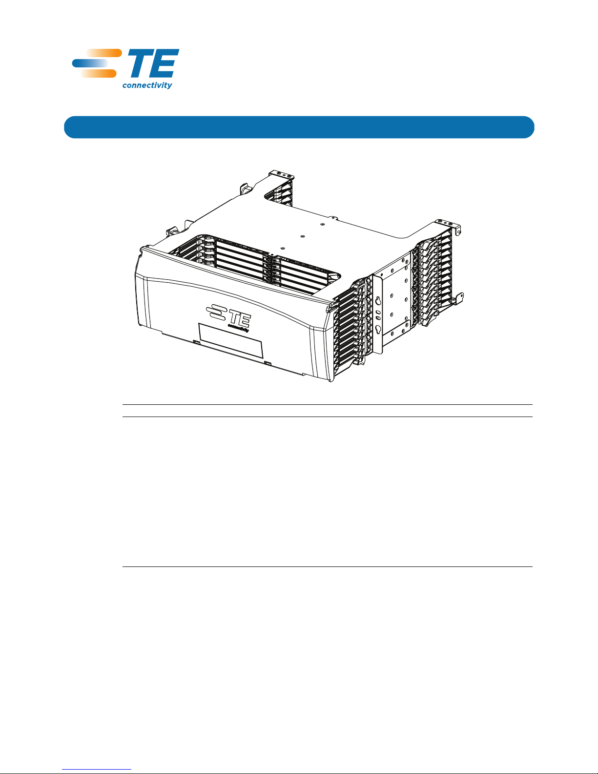
This installation manual describes the NG4access ODF Platform Standard Chassis and provides
all information needed to install this product. This product is intended to be used in a Network
Telecommunication Facilities and is suitable for installation in an Integrated Bonding Network
or a Common Bonding Network.
Content Page
24939-A
TECP-90-703 Issue 1 8/2012
NG4access ODF Platform
Standard Chassis
Installation Manual

TECP-90-703 • Issue 1 • 8/2012
Page 2
© 2012 Tyco Electronics Corportation. All Rights Reserved.
Revision History
Trademark Information
TE (icon), TE Connectivity (logo), and NG4access are trademarks of Tyco Electronics Corporation.
Admonishments
Admonishments — in the form of Dangers, Warnings, and Cautions — must be followed at all
times. These warnings are flagged by use of the triangular alert icon, shown below.
General Warning and Caution Statements
1 PRODUCT DESCRIPTION
The NG4access standard chassis is a 19-inch (48.26 cm) rack-mount, high-density fiber optic
panel providing up to 576 terminations using LC adapters (or 288 SC terminations). A
NG4access frame fully loaded with six standard chassis provides 3456 LC terminations per
frame in a GR-449 compliant footprint.
The chassis has features providing quick and easy access for connection and routing of fibers.
• Universal LC or SC adapter packs can be used with singlemode or multi-mode, APC or
UPC connectors. LC packs have 12 adapters per pack (24 per access tray). SC packs have
six adapters per pack (12 per access tray).
• Access trays can be moved toward front or rear to provide easy access to adapters from the
front or rear side of the frame.
ISSUE DATE REASON FOR CHANGE
1 08/2012 Original.
Danger: Danger is used to indicate the presence of a hazard that will cause severe personal
injury, death, or substantial property damage if the hazard is not avoided.
Warning: Warning is used to indicate the presence of a hazard that can cause severe personal
injury, death, or substantial property damage if the hazard is not avoided.
Caution: Caution is used to indicate the presence of a hazard that will or can cause minor
personal injury or property damage if the hazard is not avoided.
Danger: Avoid eye exposure to unmated connectors. Unmated connectors may emit invisible
laser radiation. Do not look directly into the end of a connector or an adapter port. Do not
inspect with a magnifying device. To ensure safety, maintain caps on unmated connectors at all
times.
Caution: Handle cables with care. Fiber optic cable stubs should be handled with care
throughout the installation procedure to avoid kinking and damage to cables.
TECP-90-703 • Issue 1 • 8/2012
Page 3
© 2012 Tyco Electronics Corporation. All Rights Reserved.
• Access trays can also be loaded with cabled modules that snap into position. Each cabled
module is pre-terminated with 24 LC or 12 SC adapter/connectors and fibers. Snap-in
MPO and VAM modules are also available.
• Routing guides manage the fibers within the chassis, allowing an access tray to be opened
or closed with no pulling or pinching of fibers.
2 MAIN COMPONENTS
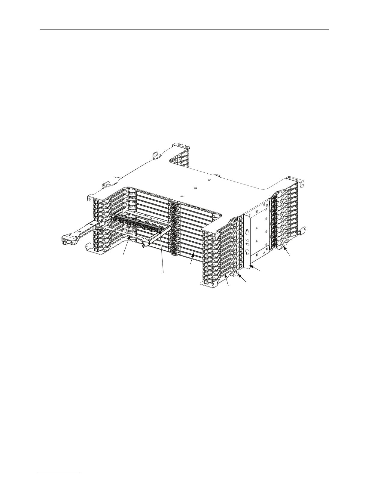
Figure 1 shows the main components of the standard chassis. They are as follows:
Figure 1. Main Components of NG4access Standard Chassis
•Access Tray—can be moved toward front or rear to provide front or rear access to adapter
packs with the associated fibers and connectors. In place of adapter packs, each access tray
may hold a snap-in cabled module, MPO module, or VAM module.
•Tray doors—swing out when an access tray is opened. Tray doors protect the individual
access trays and provide laser eye protection.
•Universal Adapter Pack (LC or SC)—can be used with singlemode or multi-mode, APC
or UPC connectors. LC packs have 24 adapters. SC packs have 12 adapters,
•Routing Guide—holds fibers in an optimal route when access trays are moved toward the
front or rear of the chassis.
•Mounting Tab—provides a physical interface for mounting the chassis on a frame. The
tabs hold four mounting screws, two on each side.
24948-A
TRAY
DOORS
ACCESS
TRAY
NOTE:
CHASSIS DOORS
NOT SHOWN
ROUTING
GUIDES
MOUNTING
TAB
GUIDE
STRIP
GUIDE
STRIP
UNIVERSAL
ADAPTER PACK
(WITH LC
CONNECTORS)

TECP-90-703 • Issue 1 • 8/2012
Page 4
© 2012 Tyco Electronics Corportation. All Rights Reserved.
•Guide Strip—provides cable management for fibers routed into the chassis on the front or
rear of the frame.
3 GROUNDING AND BONDING THE CHASSIS
The standard chassis uses thread-forming mounting screws to provide an electrical path
between the chassis and the metalwork in which it is mounted. It is required that nonconductive
coatings must be removed on the mating metal surfaces. Before installation the mating surfaces
must be cleaned and coated with an antioxidant.
4 CHASSIS INSTALLATION PROCEDURE
1. Identify the frame location where chassis will be installed. Prepare area around mounting
holes to provide a good ground (remove paint, clean, and coat with rust preventative).
2. Install screws and star washers into the two left side holes on the rack to hang the chassis
on the rack, then install screws and washers in the right two holes. See Figure 2.
Figure 2. Installing Chassis in Frame
Note: The frame has six locations for mounting of the chassis.
24940-A
TECP-90-703 • Issue 1 • 8/2012
Page 5
© 2012 Tyco Electronics Corporation. All Rights Reserved.
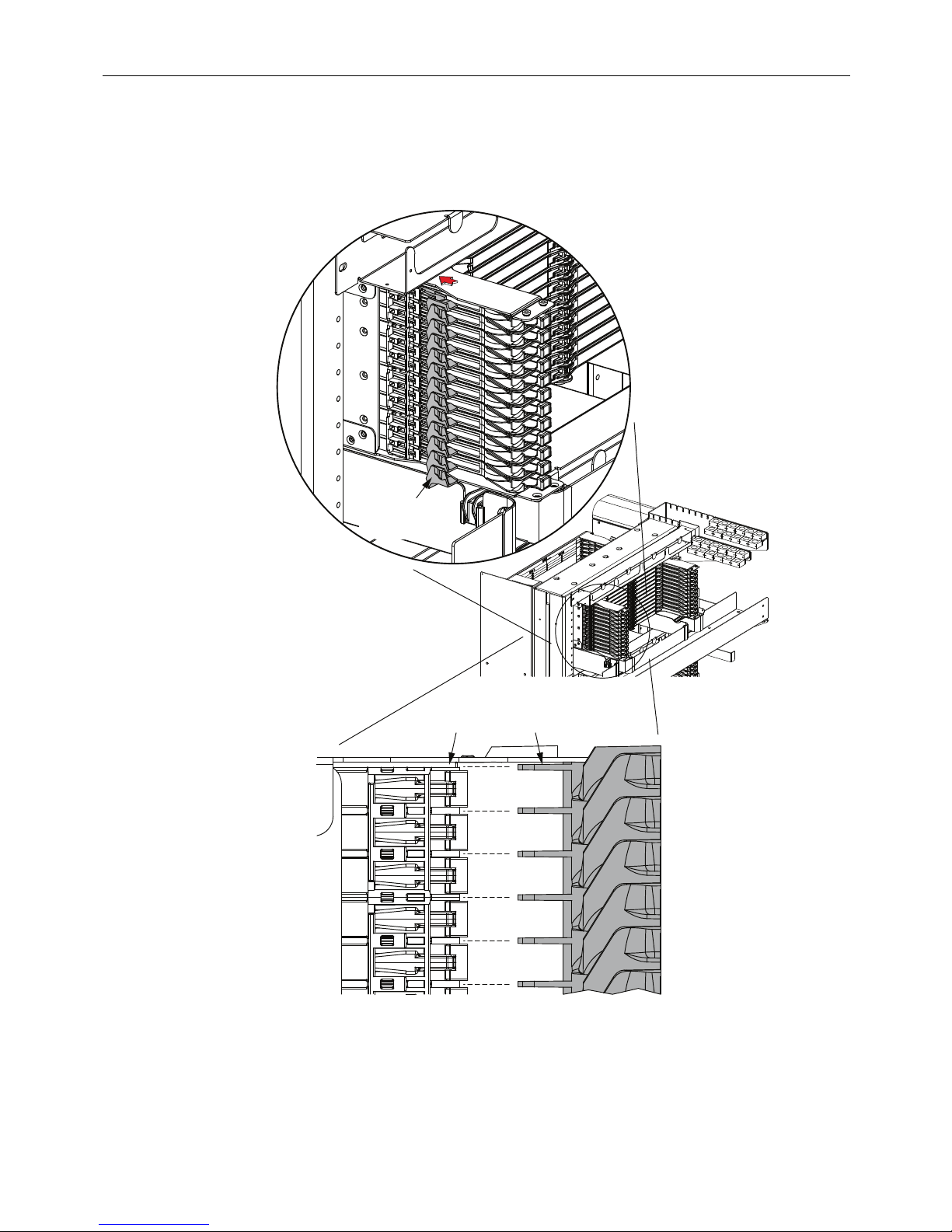
3. Install guide strips (provided) on front and rear of chassis. To install a strip, align the tabs
on the strip with the slots on the chassis as shown in rear view in Figure 3, then press the
radius limiters into place as shown. Repeat for all four locations.
Figure 3. Installing Guide Strip On Standard Chassis
PRESS RADIUS
LIMITERS INTO
PLACE
24942-A
SIDE VIEW
SLOT TAB
ALIGN TABS
WITH SLOTS
TECP-90-703 • Issue 1 • 8/2012
Page 6
© 2012 Tyco Electronics Corportation. All Rights Reserved.
5 DOOR INSTALLATION AND OPERATION
The standard chassis is equipped with a separately packed door that when installed protects the
access trays when the chassis is not being accessed.
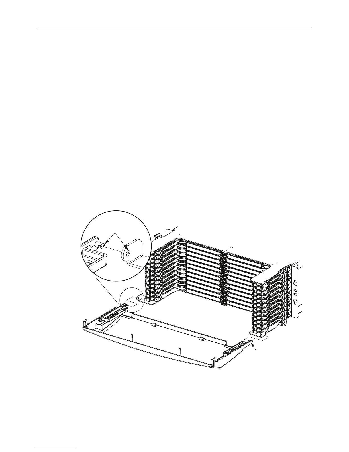
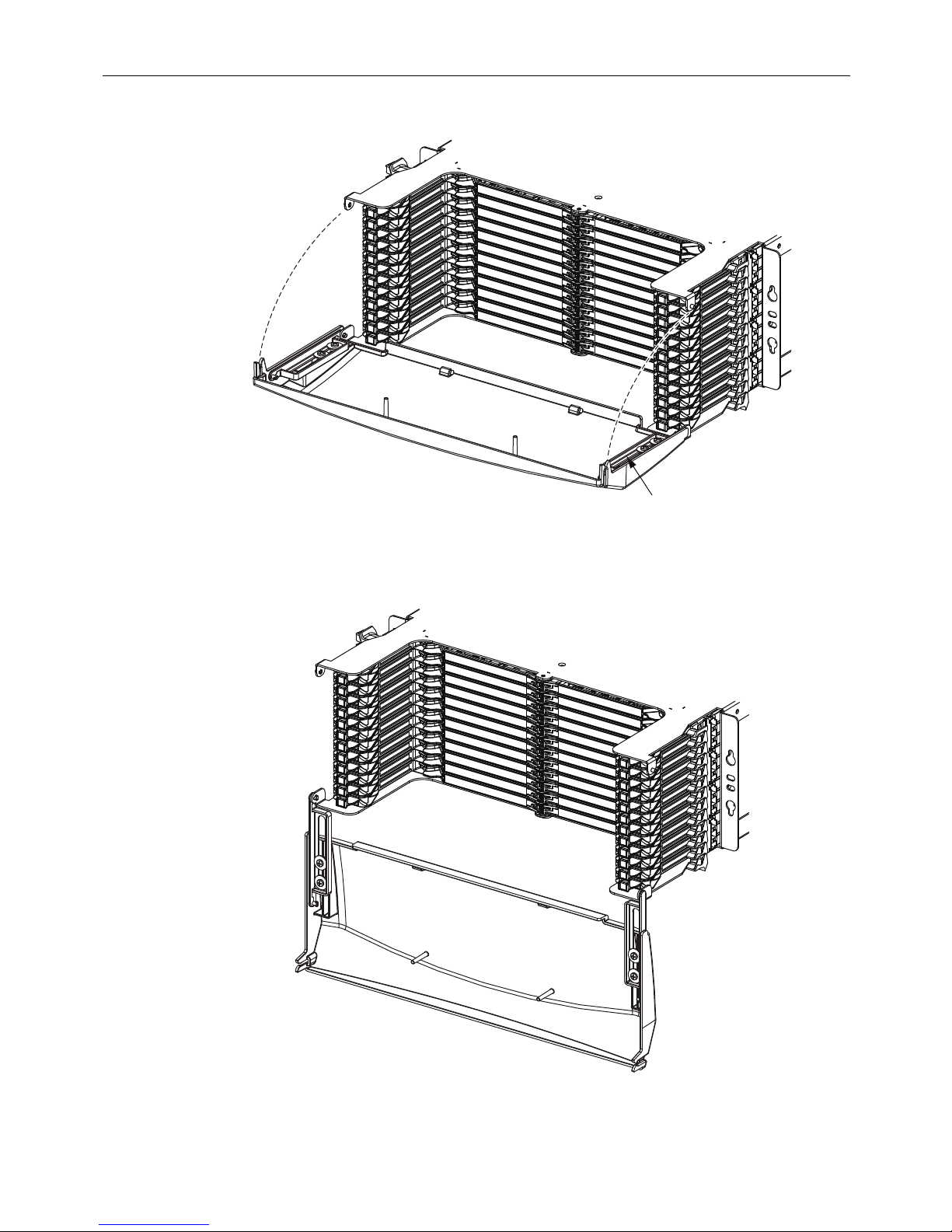
To install the door:
1. Position the door at a 90 degree angle with respect to the chassis to align the tabs with the
slotted hole, as shown in Figure 4. Push out slightly on the mounting arms to clear the
brackets, allowing the tabs to slide into the slotted hole.
2. Retract the slides and flip up the door to snap the door into a closed position as shown in
Figure 5.
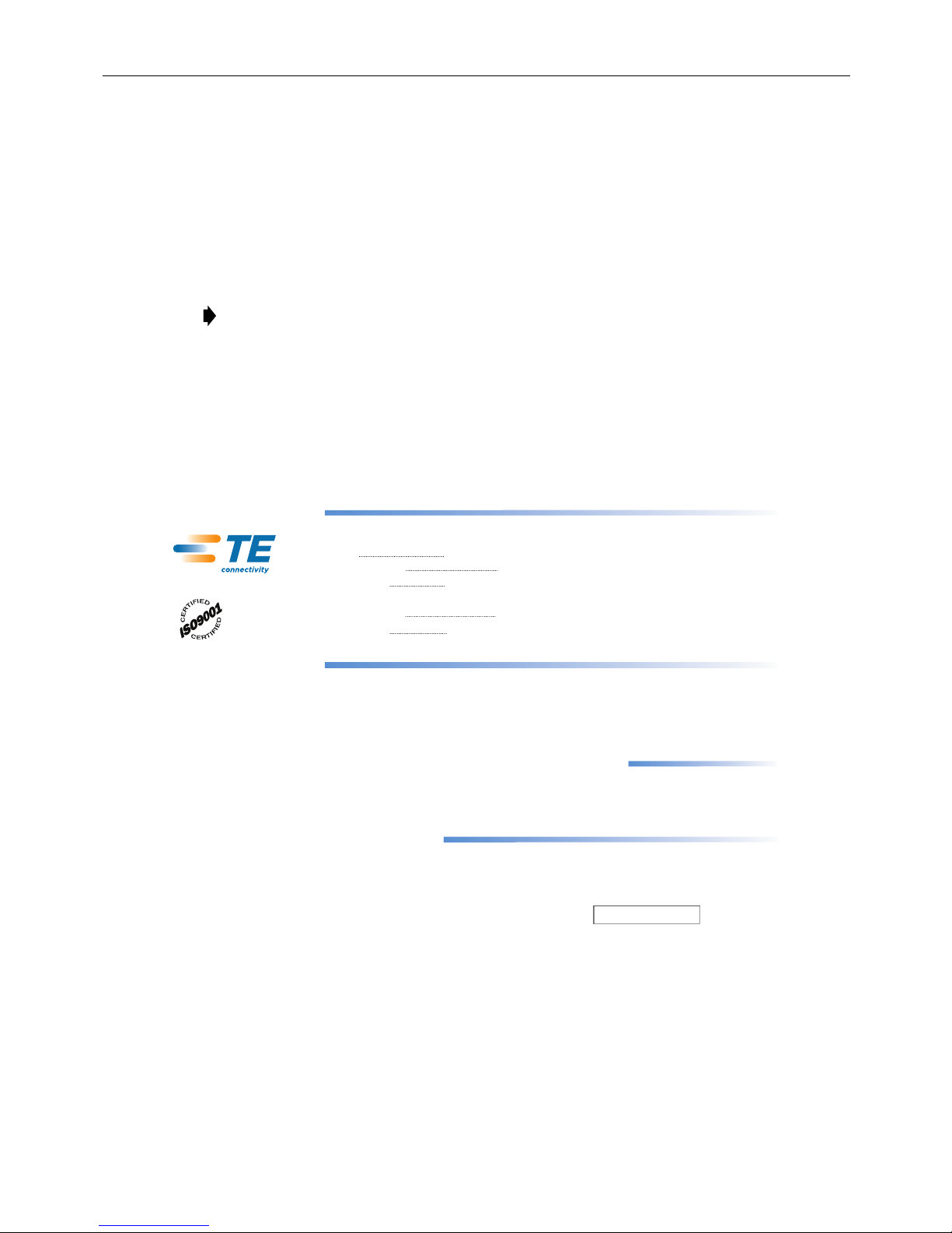
To open the door:
1. Grasp the door at the top and unsnap it from the chassis.
2. Allow the door to hang down in the full open position shown in Figure 6.
To close the door:
Retract the slides and flip up the door to snap the door into a closed position as shown in
Figure 5.
Figure 4. Lining Up Door With Slots
ALIGN TABS
WITH SLOTTED
HOLE
EXTEND SLIDES
AND BEND TO
CLEAR BRACKET
25073-A
TECP-90-703 • Issue 1 • 8/2012
Page 7
© 2012 Tyco Electronics Corporation. All Rights Reserved.
Figure 5. Closing Door
Figure 6. Door in Full Open Position
RETRACT SLIDES AND
FLIP UP TO CLOSE
25075-A
25074-A
TECP-90-703 • Issue 1 • 8/2012
Page 8
© 2012 Tyco Electronics Corportation. All Rights Reserved.
6 WHERE TO FIND OTHER INFORMATION
6.1 Adapter Pack and Module Installation Instructions
Refer to the laminated cards hanging on the rear of the frame.
6.2 Routing of Cables, Fibers, and Patch Cords
For cable routing on the rear of the frame, refer to the laminated cards hanging on the rear of the
frame. For patch cord routing, refer to the laminated cards hanging on the front of the frame.
6.3 Phone Numbers, Mail Address, Email Address, and Product Portal
Refer to banner below.
Note: This product is designed for use with RBR (Reduced Bend Radius) fiber.
13944-U
Contents herein are current as of the date of publication. TE reserves the right to change the contents
without prior notice. In no event shall TE be liable for any damages resulting from loss of data,
loss of use, or loss of profits and TE further disclaims any and all liability for indirect, incidental,
special, consequential or other similar damages. This disclaimer of liability applies to all products,
publications and services during and after the warranty period.
PRODUCT PORTAL:
PDF copies of this manual and other DELTAccess manuals are available
for downloading using a visual regonition app on a smartphone
and the QR code on the front of the frame
PRODUCT INFORMATION AND TECHNICAL ASSISTANCE:
Publication Number:
WRITE:
Tyco Electronics Corporation
PO Box 1101,
Minneapolis, MN 55440-1101, USA
PHONE:
U.S.A. or CANADA
Sales: 1-800-366-3891
Extension 73000
(Direct 1-952-917-3000)
Technical Assistance: 1-800-366-3891
Extension 73475
(Direct 1-952-917-3475)
TECP-90-703
Table of contents


