ATX MAXNET II Platinum Series User manual

MP3 Active/Passive Chassis
Installation & Operation Manual
CCAP™
Com
pliant
1.2 GHz

MAXNET®II is a registered trademark of ATX in the United States and/or other countries. Products or features contained herein may be covered by one or more U.S. or foreign
patents. Other non-ATX product and company names in this manual are the property of their respective companies.
Although every effort has been taken to ensure the accuracy of this document it may be necessary, without notice, to make amendments or correct omissions.
Specications subject to change without notice.

TABLE OF CONTENTS
Page
1. PRODUCT DESCRIPTION........................................................................................................................ 1-1
1.1. Functional Diagrams.......................................................................................................................... 1-2
1.2. Technical Specications .................................................................................................................... 1-2
2. INSTALLATION ......................................................................................................................................... 2-1
2.1. Module Installation Into the MP3 Chassis ......................................................................................... 2-1
2.2. Powering the Active MP3 Chassis..................................................................................................... 2-1
2.3. Remote Chassis Power Applications................................................................................................. 2-2
2.4. Module Power Requirements ............................................................................................................ 2-3
3. HARDWARE NETWORK SET-UP............................................................................................................. 3-1
3.1. LED Indicators................................................................................................................................... 3-1
3.2. Ethernet Port ..................................................................................................................................... 3-1
4. STATUS MONITORING ............................................................................................................................. 4-1
4.1. Chassis Interface Options ................................................................................................................. 4-1
4.2. Software Network Set-up................................................................................................................... 4-1
4.3. Web Interface .................................................................................................................................... 4-1
4.4. Module Replacement......................................................................................................................... 4-2
4.5. Factory Reset .................................................................................................................................... 4-2
4.6. SNMP Parameters............................................................................................................................. 4-3
4.7. Default Alarm Thresholds .................................................................................................................. 4-6
4.8. SNMP MIBs Required ....................................................................................................................... 4-7
5. SETTING UP A MAXNET®II CHASSIS TO USE A MEINBERG NTP SERVER LOCAL HOST PC......... 5-1
5.1. Installation ......................................................................................................................................... 5-1
5.2. Starting the NTP Server .................................................................................................................... 5-1
5.3. Setting up the MAXNET®II Chassis .................................................................................................. 5-1
6. FTP SERVER FIRMWARE LOAD INSTRUCTIONS ................................................................................. 6-1
7. MAINTENANCE & TROUBLESHOOTING................................................................................................ 7-1
7.1. Maintenance...................................................................................................................................... 7-1
7.2. Troubleshooting................................................................................................................................. 7-1
8. SERVICE & SUPPORT.............................................................................................................................. 8-1
8.1. Contact ATX Networks....................................................................................................................... 8-1
8.2. Warranty Information ......................................................................................................................... 8-1
8.3. Safety ................................................................................................................................................ 8-1
MAXNET®II – MP3 Active / Passive Chassis – Installation & Operation Manual i

Index of Figures and Tables
Figures
#1 Active Chassis Functional Diagram.............................................................1-2
#2 Remote Powering ........................................................................................2-3
#3 Redundant Powering ...................................................................................2-3
#4 Redundant Remote Powering .....................................................................2-3
Tables
#1 Ordering Information....................................................................................1-1
#2 Active Chassis Technical Specications ......................................................1-2
#3 Terminal Block Pin Assignments..................................................................2-2
#4 Ethernet Interface Pin Assignments ............................................................3-2
#5 Ethernet Interface LED Indicators ...............................................................3-2
#6 Administration Level SNMP Parameters .....................................................4-3
#7 Common Module SNMP Parameters ..........................................................4-3
#8 RF and Optical Switch SNMP Parameters ..................................................4-4
#9 MPTX Laser SNMP Parameters..................................................................4-5
#10 Misc. SNMP Parameters .............................................................................4-5
#11 General IETF MIBs Required - All Modules.................................................4-7
#12 General SCTE HMS MIBs Required - All Modules......................................4-7
#13 Module-Specic SCTE HMS MIB’s Required..............................................4-7
ii MAXNET®II – MP3 Active / Passive Chassis – Installation & Operation Manual

PRODUCT DESCRIPTION
1. Product Description
The MP3 chassis is a 3RU design that comes in both a passive and active conguration. Both congurations include options
for dual cable management bars and a large cable management tray as well as user congurable horizontal and vertical
cable management systems. The MP3 active chassis also include a ber management tray that can be congured into two
positions.
The passive and active chassis’ can accommodate up to 24 single-width passive modules (DC Logic A/B RF Switch; 2,
4, 8, dual 4-way and triple 2-way splitters\combiners; DC & triple DCs) or up to 12 dual-width modules (16-way splitter\
combiners).
The active chassis can accommodate all the modules that a passive chassis can, but also up to 12 dual-width active modules
(amplier, power supply, optical receiver\transmitter, RF Switch).
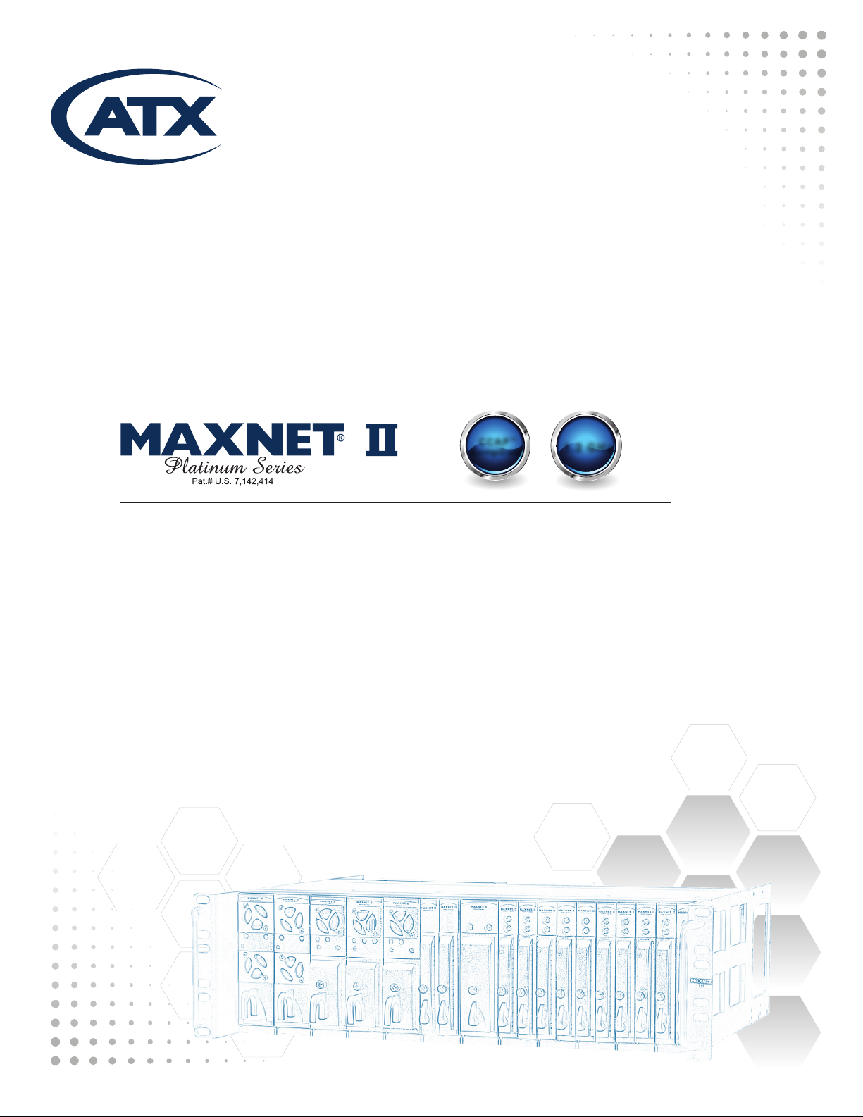
The active chassis comes with a +24 VDC power interface backplane/rail and a removable communications module that
draws power from the rail. This communications module can be removed without affecting the operation of the modules in the
chassis by removing the two Phillips screws on either side that fasten it to the chassis. All active modules are hot-swappable.
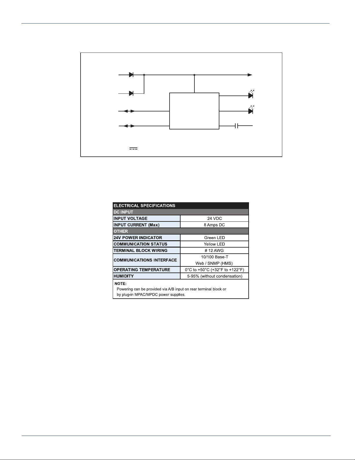
Power is supplied to the backplane by installing an MPAC or MPDC power supply into one of the chassis slots or by remotely
powering the chassis from an external 24 VDC supply. The MP3 active chassis is equipped with an HMS compliant SNMP
management system. An RJ-45 port is used for both set-up and status monitoring. No custom software is required.
Please refer to the web page for up-to-date specications – www.atxnetworks.com
__________________________________________________
1Provided that the chassis is not being solely powered via the terminal block on the comm module, there would simply be no alarms and no remote
adjustment of parameters. The modules would continue to run with the last set values.
2It is not recommended to hot swap a power supply module into a full chassis if there is no other power supply present. The current surge to supply a
full rack of active modules would be stressful on the electrical contacts during mating and may reduce the lifespan of the chassis and power supply. It
is recommended that you install the power supply rst, then apply AC or DC input to the power supply connector.
MAXNET®II – MP3 Active / Passive Chassis – Installation & Operation Manual 1-1
CHAPTER 1: PRODUCT DESCRIPTION
Table #1: Ordering Information
(See http://www.atxnetworks.com/pdf/ANW0614_MNII_ChassisCableOptns.pdf
for photos of various options)
Part Number Description
MP1 1RU Passive Chassis with Cable Management Bar
MP3B 3RU Passive Chassis with Dual Cable Management Cable Bars
MP3H 3RU Passive Chassis with Configurable Horizontal Channel Cable Management
MP3V 3RU Passive Chassis with Configurable Vertical Channel Cable Management
MP3T 3RU Passive Chassis with Large Cable Management Tray
MP3R 3RU Passive Reverse Chassis
MP3BA 3RU Active Chassis with Dual Cable Management Cable Bars
MP3RA 3RU Active Reverse Chassis
MP3HA 3RU Active Chassis with Configurable Horizontal Channel Cable Management
MP3VA 3RU Active Chassis with Configurable Vertical Channel Cable Management
MP3TA 3RU Active Chassis with Large Cable Management Tray
MPRB Round Cable Management Steel Bar
MPBAR Flat Cable Management Steel Bar
MPFT Fiber Management Tray (includes 12 push fit plastic fiber guides) for 3RU Chassis
MPLT Large Cable Management Tray (includes clips)
MP3FA 3RU Active Chassis for F Connector Optics Platform (includes rear rails for patch
panels & front fiber tray)
MP3FA-COM Replacement Communication Module for MP3FA
MP3FA-T Replacement Fiber Management Tray for MP3FA
MPHKIT Configurable Horizontal Channel Cable Management Kit

1.1. Functional Diagrams
1.2. TechnicalSpecications
1-2 MAXNET®II – MP3 Active / Passive Chassis – Installation & Operation Manual
CHAPTER 1: PRODUCT DESCRIPTION
Figure #1: Active Chassis Functional Diagram
Table#2:ActiveChassisTechnicalSpecications
Active Chassis: DC Power & Communications
+24 V
CHASSIS
BUS
PWR
CHASSIS COMM.
(TO ACTIVE
MODULES)
INT COMM
CHASSIS
ALARM
24 VDC B
24 VDC A
RELAY
N.O.
CHASSIS MONITOR,
CONTROL &
COMMUNICATIONS
SNMP (HMS)/
ETHERNET
COMM
INPUT CURRENT: 8.0 AMPS MAX
INPUT VOLTAGE: 24 VOLTS DC

INSTALLATION
2. Installation
The MP3 is a 3RU chassis and comes pre-assembled and ready to mount to any existing 19” rack cabinet hub system using
10/32” rack screws.
NOTE: This equipment is intended for installation in a RESTRICTED ACCESS LOCATION only.
NOTE: Not for use in a computer room as dened in the Standard for Protection of Electronic Computer/Data Processing
Equipment, ANSI/NFPA 75.
Rack Mounting Precautions
a) Elevated Operating Ambient - If installed in a closed or multi-unit rack assembly, the operating ambient temperature
of the rack environment may be greater than room ambient. Therefore, consideration should be given to installing
the equipment in an environment compatible with the maximum ambient temperature (35ºC) specied by the
manufacturer.
b) Reduced Air Flow - Installation of the equipment in a rack should be such that the amount of airow required for
safe operation of the equipment is not compromised.
c) Mechanical Loading - Mounting of the equipment in the rack should be such that a hazardous condition is not
achieved due to uneven mechanical loading.
d) Circuit Overloading - Consideration should be given to the connection of the equipment to the supply circuit
and the effect that overloading of the circuits might have on overcurrent protection and supply wiring. Appropriate
consideration of equipment nameplate ratings should be used when addressing this concern.
e) Reliable Earthing - Reliable earthing of rack-mounted equipment should be maintained. Particular attention should
be given to supply connections other than direct connections to the branch circuit (e.g. use of power strips).”
2.1. Module Installation Into the MP3 Chassis
All MAXNET II active and passive chassis have 24 grooves that act as guide slots for the active and passive modules.
Passive modules and the DC Logic Switch can be inserted into any of the 24 slots. Active modules must be inserted into the
odd number slots indicated by the white markers on the bottom rail of the chassis. These odd numbered slots are the
only slots that will allow an active module to be connected to the active chassis backplane to receive power and allow monitor
and control of the module. To insert a module, align the module guide rails to the chassis guide slots and then gently slide
the module into a locked position (the module should be ush against the top and bottom rail of the chassis). No mounting
hardware is required. To remove a module, grab the front handle on the module and gently lift and pull back the module until
it is clear of the chassis guide rails.
NOTE: When installing the MPAC or MPDC Power Supply, the GND bonding terminal #1 on the back of the MPAC or
MPDC Power Supply shall be connected to the chassis ground lug.
2.2. Powering the Active MP3 Chassis
The MP3 active chassis can be powered by power supply modules (MPAC-110, MPAC-220 or MPDC) installed in one of the
slots of the chassis, or by connecting power directly to one or both of the terminal block inputs on the rear of the chassis. Both
connections are not necessary unless redundancy is required. If the source of 24 VDC is not an MPXX power supply, the line
should be fused at a minimum with a 10 Amp slo-blo fuse. A disconnect device is required between the 24 VDC supply and
the Chassis remote power terminals.
MAXNET®II – MP3 Active / Passive Chassis – Installation & Operation Manual 2-1
CHAPTER 1: PRODUCT DESCRIPTION CHAPTER 2: INSTALLATION

2.3. Remote Chassis Power Applications
CHAPTER 2: INSTALLATION
RLY
NO
RLY
COM
+24V
BCOM +24V
A
NAME DESCRIPTION
+ 24V A +24 VDC input A
COM Ground
+24V B +24 VDC input B
RLY COM Common Relay Contact
RLY NO Normally Open Relay Contact (fault
condition if open circuit to RLY COM)
Table #3: Terminal Block Pin Assignments
* recommended minimum of #12 gauge wire rated for up to 10A
2-2 MAXNET®II – MP3 Active / Passive Chassis – Installation & Operation Manual

* In any of the examples above, be sure to refer to the next section for module power requirements. In any redundant
scenario, if a power supply fails, the load on any remaining power supply must not exceed 8 amps.
2.4. Module Power Requirements
CHAPTER 2: INSTALLATION CHAPTER 2: INSTALLATION
MAXNET®II – MP3 Active / Passive Chassis – Installation & Operation Manual 2-3
Figure #2: Remote Powering Figure #3: Redundant Powering
Figure #4: Redundant Remote Powering
Module
Max Current (A) 8 0.29 0.52 0.46 0.29 0.52 0.03 0.14 0.47 0.52
MPAC / MPDC
MPRX-8 /
MPRX-16
MPRX2-8
MPRXRR-16 /
MPRXRR-8
MPRX-DC /
MPRX2-DC
MPRX2-DC
MPRFA/B
QMP200
QMP1000
(< 22 dB Gain)
QMP1000
(> 22 dB Gain)

CHAPTER 2: INSTALLATION
2-4 MAXNET®II – MP3 Active / Passive Chassis – Installation & Operation Manual
This page left intentionally blank.

HARDWARE NETWORK SET-UP
3. Hardware Network Set-up
The MP3 active chassis can be easily connected to an existing network through the use of a patch cable connected between
the network port on the rear of the chassis and any switch or router. For a connection directly to a PC or laptop, use a
crossover cable. This product has been veried to work on Windows XP/2000 and Linux operating systems.
3.1. LED Indicators
There are four LED’s visible at the rear of the chassis. Two small square LEDs on the RJ45 port itself (see the next section
for details on these), a large yellow ‘COM’ and green ‘24V’ LED.
The ‘24V’ LED indicates the presence of power to the chassis and comm module, it should always be solid and bright.
The ‘COM’ LED will be solid during the boot cycle of the device but should start blinking after approximately 2 minutes. It must
always be blinking during regular operation to indicate the monitoring software is running.
3.2. Ethernet Port
The RJ45 Ethernet port visible at the rear of the chassis is actually the DC-ME-01T-C embedded device server, manufactured
by Digi International and loaded with custom ATX rmware. The following gures and text were taken directly from the
“Digi Connect ME & Digi Connect Wi-ME Hardware Reference”. For more information, please go to www.digi.com.
The Ethernet connector is an 8-wire RJ-45 jack that meets the ISO 8877 requirements for 10/100BASE-T. See the following
gure and table for pin orientation and pin assignments.
The yellow LED indicates whether a valid network connection is present. It should be solid. Otherwise, check the network
cable or the piece of hardware that has been connected to the network cable (switch, router or PC’s network card).
The green LED indicates network activity. It will be solid during any boot process (approx 2 min) and then blink if there is any
network trafc. If it remains solid, this may be indicative of corrupt hardware – contact ATX Networks.
MAXNET®II – MP3 Active / Passive Chassis – Installation & Operation Manual 3-1
CHAPTER 3: HARDWARE NETWORK SET-UPCHAPTER 2: INSTALLATION
Reset
Button
Network Activity
LED Status
Link Status
LED
Status Monitoring
Activity LED
Chassis Power
LED Status

3-2 MAXNET®II – MP3 Active / Passive Chassis – Installation & Operation Manual
CHAPTER 3: HARDWARE NETWORK SET-UP
Table #4: Ethernet Interface Pin Assignments
Table #5: Ethernet Interface LED Indicators

STATUS MONITORING
4. Status Monitoring
4.1. Chassis Interface Options
The Active MAXNET II product line can be monitored and controlled in either of two ways:
a) A free, web-based interface. This comes pre-installed on every chassis and provides a user friendly method of
conguring the administrative set-up and all monitoring and control. It is based on SNMP, but requires little knowledge
of SNMP. Any Internet browser, such as Internet Explorer, is all the software that is required.
b) Any third-party SNMP Management software (eg. www.castlerock.com, www.ndt-inc.com/SNMP/MIBrowser.html )
may be purchased separately. These suites tend to be expensive and not as user friendly as the web interface. The
web interface is also still required for administrative set-up. The 3rd party interface is recommended only for systems
that have an existing SNMP architecture. All MIBs (Management Information Bases) are freely downloadable from
the SCTE (www.scte.org/standards). ATX was able to support all modules using the SCTE standard HMS MIBs, so
no custom MIBs are required.
4.2. Software Network Set-up
a) Recommended: Connect the chassis to a PC/laptop directly with a cross-over network cable.
Alternative: Connect the chassis to a switch or router using a patch network cable.
b) Enter the IP address of the chassis as the URL in a web browser. By default (factory reset), this will be 192.168.0.1.
If the device does not respond, see Troubleshooting section at the end of this document.
c) The login page should appear. Login as administrator (default password for all levels is the lower case name of the
level, i.e. Observer password is observer).
d) The conguration settings page should appear. It is important to either use DHCP or (preferably) assign a unique
IP address to each MP3 chassis that will be on the same subnet as your DHCP server assigns addresses. “Same
Subnet” refers to an IP address that has the same rst three octets, but a unique fourth octet e.g. 192.168.0.1 and
192.168.0.2 are on the same subnet.
e) Obtain a list of IP addresses from your IT department to use for your chassis’ and assign them one by one. If DHCP
is chosen, then this is not required, but you may have trouble nding out what IP address the DHCP server assigned
to each chassis, and it may change during a reboot of the chassis or DHCP server, so it is not recommended unless
the DHCP server is set to assign static IP addresses to the unique MAC addresses of each chassis installed.
f) There are several other options that can be set at this time, see Table 6 for a list.
g) Select ‘save changes’ and reboot. The device will take approximately 90 seconds before it is responsive again.
Remember that your PC/laptop must be set to the same subnet to ‘see’ it, so if you just assigned an IP address
other than 192.168.0.x, then you will need to change your PC’s IP again. It is recommended you change all chassis
IP addresses before reverting your PC back to DHCP.
4.3. Web Interface
The MAXNET II chassis uses an integrated web page to supplement the SNMP management. All conguration of the chassis
(static IP address, trap/email recipients, rmware upgrades, etc) must be done through the web page. Simply use any web
browser (Internet Explorer, Firefox, etc) and enter the IP address of the chassis as the URL. Login as administrator to modify
conguration and have full read/write access to monitor and control modules. Login as Operator to have full read/write access
or login as observer to have read-only access. There is only one password per login level.
MAXNET®II – MP3 Active / Passive Chassis – Installation & Operation Manual 4-1
CHAPTER 3: HARDWARE NETWORK SET-UP CHAPTER 4: STATUS MONITORING

CHAPTER 4: STATUS MONITORING
4-2 MAXNET®II – MP3 Active / Passive Chassis – Installation & Operation Manual
4.4. Module Replacement
In order to facilitate the replacement of any MAXNET II module, the software set-up information of the module such as HI
and LO alarm thresholds and alias are stored in the chassis itself and not the module. If any module is removed the chassis
and the same module or another of the same type is inserted into that slot of the chassis, then this conguration data will be
maintained.
This is not true for switch parameters though. In order to meet switch time specications at the module, this information
is stored within the module itself and therefore will travel with it wherever it is installed next. These parameters include
hysteresis, switch threshold, wait to restore time, etc.
4.5. Factory Reset
A factory reset will restore the chassis to the state which it left the ATX production facility.
4.5.1. Parameters That Will be Changed
IP address = 192.168.0.1
NetMask = 255.255.255.0
Gateway = 192.168.0.254
Passwords set to same text (but all lower case) as the login level. e.g. Operator password is operator.
All analogue and discrete alarm thresholds of modules will be reset to default values (except RF and optical switch data as
mentioned in the Module Replacement section above).
Alarm log will be cleared.
4.5.2. Purpose
Common reasons for requiring a factory reset are:
a) The chassis is unresponsive, or the IP address is not known
b) The Administrator password has been forgotten
c) The yellow COMM LED does not blink after the 2 minute boot cycle, even after a power cycle or press of the RESET
button
4.5.3. Method
If you are sure you want to factory reset, hold down the RESET button near the RJ45 port for at least 10 seconds. The yellow
COMM LED will be solid-on during this time, and once it turns off you can release the button and the reboot process will
begin.

4.6. SNMP Parameters
MAXNET®II – MP3 Active / Passive Chassis – Installation & Operation Manual 4-3
CHAPTER 4: STATUS MONITORINGCHAPTER 4: STATUS MONITORING
Table #6: Administration Level SNMP Parameters
Display Name Description
Hostname/ Domain Name Optional elds.
IP Address, Subnet Mask,
Default Gateway
Dene the static IP address of the chassis. This address is maintained during power cycles and rmware upgrades. A factory
reset will revert the IP back to 192.168.0.1
DNS Servers
Enter the domain name server to be able to enter textual URLs instead of only IP
addresses.
This affects how you can enter data in some elds below such as NTP server and SMTP server.
NTP Server Network Time Server (e.g. time.windows.com). If there is no network time server available leave this blank. All times are then
counting from midnight, Jan 1st, 1970 as the start-up time (this is an internet standard).
Time Zone Only used if NTP server used. Adds local time zone offset to UTC time. e.g. for
Eastern Standard Time Zone, enter ‘UTC+5:0’.
Read-write Community Name SNMP required variable.
Read-only Community Name SNMP required variable.
Default Trap Community Name SNMP required variable.
Trap Recipient List List up to 10 IP addresses that are to receive SNMP traps
(requires an SNMP trap receiver to interpret these alarm messages).
System Name, Location, Contact Optional SNMP elds. User can store information about this particular chassis for reference later.
SMTP Server Outgoing mail server.
If you do not specify a DNS server above, then the server must be entered as an IP address.
Email Recipient List List up to 5 email addresses that are to receive an email form of the traps.
SMTP Username, Password If authentication required (ask your IT department), you must enter an email user name and password.
Display Name Description HMS MIB Variable Read Write /
Read Only
Model
ATX model number (note, in empty slots you can enter
passive, dual-passive, or empty to populate the overview
page with passive picture placeholders).
entPhysicalModelName RO
Description Description of the module. entPhysicalDescr RO
Name Indicates the slot of the chassis the module is in. entPhysicalName RO
Alias
Optional user dened eld - added to fth variable binding
of traps and emails
e.g. set this to “Node 69” for a given Receiver and any
alarms generated by this receiver will have “Node 69” in the
description. Otherwise, it would only contain the IP
address of the chassis, the Model and Name (slot number).
entPhysicalAlias RW
Manufacturer ATX entPhysicalMfgName RO
Asset I.D Optional user settable eld (suggestions: enter in a custom
serial number or purchase order # for tracking). entPhysicalAssetID RW
Serial No Module’s serial number. entPhysicalSerialNum RO
Hardware Rev Hardware rev of module. entPhysicalHardwareRev RO
Firmware Rev Firmware rev of module. entPhysicalFirmwareRev RO
Temperature [C] Module’s current heatsink temperature. heCommonTemperature RO
Alarm Detection Control
detectionEnabled: normal operation, with active alarms
detectionDisabled: used to temporarily disable alarms/traps
from this module
detectionEnabledandRegenerate: enter detectionEnabled
state while regenerating all alarm table entries
heCommonAlarmDetectionControl RW
Fan Unit Status Alarm status of the fan. heFanUnitAlarm RO
Voltage In [Volt] Measured voltage supplied to the module from the chassis
(nominally 24V). hePsUnitVoltageIN RO
Current In [mA] Current taken from the 24V rail by the module. hePsUnitCurrentIN RO
Power In [Watts] P.S. Voltage * P.S. Current hePsUnitPowerIN RO
Table #7: Common Module SNMP Parameters

4-4 MAXNET®II – MP3 Active / Passive Chassis – Installation & Operation Manual
CHAPTER 4: STATUS MONITORING
Display Name Description HMS MIB Variable Read Write /
Read Only
Switch Mode Automatic : switching based on threshold
Manual : switch forced to Default position
heRFSwitchMode /
heOpSwitchMode RW
Switch Control Default position of switch (PathA or PathB only). heRFSwitchControl /
heOpSwitchControl RW
Switch Revert Enable
On: switch will revert back to default position if power
returns to it (also, must be in automatic mode and
hysteresis accounted for).
heRFSwitchRevertEnable /
heOpSwitchRevertEnable RW
Switch State Current position of the switch (PathA or PathB only). heRFSwitchState / heOpSwitchState RO
Switch Fail-Over Status Fault if RF Sw Control not equal to RF/Opt Sw State. heRFSwitchFailoverStatus /
heOpSwitchFailoverStatus RO
Switch Both Input Status Fault if either switch input is below RF/Opt Sw Input
Power Threshold.
heRFSwitchBothInputStatus /
heOpSwitchBothInputStatus RO
Switch Hysteresis [dB]
Only values >= 0 are acceptable. e.g. If 2 dB , switch
will occur if power falls below RF Sw Input Power
Threshold, but does not return until power exceeds RF
Sw Input Power Threshold + 2 dB (*must also be in
automatic mode, revert-enable on and wait to restore
time expired).
heRFSwitchHysteresis /
heOpSwitchHysteresis RW
Switch Wait to Restore
Time [sec]
Time-based hysteresis. Same principle as above, but
time delayed switching if default path power returns.
heRFSwitchWaitToRestoreTime /
heOpSwitchWaitToRestoreTime RW
Switch Input Level Measured input level of switch. heRFSwitchInputRFLevel /
heOpSwitchInputRFLevel RO
Switch Input Power
Threshold [dBm] User dened switch threshold. heRFSwitchSetInputPowerThreshold /
heOpSwitchSetInputPowerThreshold RW
Switch Output Description Description of the output. heRFSwitchOutputDescription /
heOpSwitchOutputDescription RO
Switch Wavelength
Optional, user-settable integer to store the wavelength
of operation. This value has no effect on the operation
of the device.
heOpSwitchSelectWavelength RW
Switch Input Status
If RF/Opt Input power is below the input power
threshold, then this discrete variable will be in fault,
generating an alarm condition.
heRFSwitchInputStatus /
heOpSwitchInputStatus RO
Switch Input Description Identies inputs as either path A or path B. heRFSwitchInputDescription /
heOpSwitchInputDescription RO
Table #8: RF and Optical Switch SNMP Parameters

MAXNET®II – MP3 Active / Passive Chassis – Installation & Operation Manual 4-5
CHAPTER 4: STATUS MONITORING CHAPTER 4: STATUS MONITORING
Display Name Description HMS MIB Variable Read Write /
Read Only
Input AGC Mode
Automatic Gain Control mode, if set to on then the broadcast
digital attenuator is automatically adjusted to provide RF power
levels at laser input for optimum OMI.
heOpTxInputAGCMode RW
Input Modulation Mode
Either CW or modulated. This variable affects the calibration of
the RF power detector. There is approx a 2 dB difference seen
by the power detector if a CW or modulated carrier of the same
power is applied.
heOpTxInputModulationMode RW
Input Attenuation, BC
Input Attenuation, NC
Input digital attenuators. See MPTX functional diagrams to see
location of the BC (Broadcast) and NC (Narrowcast)
attenuators. 0-15 dB in 0.5 dB steps.
heOpTxInputRFPadLevel RW
Laser Temperature Laser Temperature. heOpTxLaserTemp RO
Laser Bias Current Laser Bias Current. heOpTxLaserBiasCurrent RO
Laser Output Power
If a 10dBm laser is ordered, this variable will be close to 10 dB,
with some variation as individual lasers are tuned for optimum
OMI.
heOpTxLaserOutputPower RO
Laser TEC Current Thermo-Electric cooler current. heOpTxLaserTECCurrent RO
Laser Type Typically “Cooled DFB”. heOpTxLaserType RO
Laser Wavelength Factory set wavelength of laser. heOpTxLaserWavelength RO
Laser Output Status A read-only eld to indicate what Laser On/Off control is set to. heOpTxLaserOutputStatus RO
Laser On/Off Control A writable eld. Laser is muted if set to off. heOpTxLaserOnOffControl RW
Table #9: MPTX Laser SNMP Parameters
Display Name Description HMS MIB Variable Read Write /
Read Only
OptRx Input Power Measured optical power input (max +3dBm). heOpRxInputPower RO
OptRx Input Wavelength
Optional, user-settable integer to store the wavelength of
operation. This value has no effect on the operation of the
device.
heOpRxInputWavelengthControl RW
OptRx Input Status If optical input power is beyond thresholds, this will be in fault
condition. heOpRxInputStatus RO
OptRx Output Control Allows the user to mute the RF output. heOpRxOutputControl RW
OptRx Output RF
Attenuation
Control of RF output attenuation level (0-31.5 dB in 0.5 dB
steps). heOpRxOutputRFPadLevel RW
RF Amp Output
Description Description of the approx gain value of the amp. heRFAmpOutputDescription RO
RF Amp Output Level
[dBmv] Composite RF level at output of amp. heRFAmpOutputLevel RO
Voltage Out Measured voltage supplied to the chassis.
(power supply modules only) hePsOutputVoltage RO
Current Out Current supplied to the 24V rail by the module.
(power supply modules only) hePsOutputCurrent RO
Power Out Voltage Out * Current Out.
(power supply modules only) hePsOutputPower RO
Table #10: Misc SNMP Parameters

4.7. Default Alarm Thresholds
To change a modules Alarm Threshold from their default settings, log into the appropriate chassis and using the GUI click on
the image of the module you desire to change. This will bring you to the parameters page for that particular module. From
here, a simple click on the Analog tab at the top of the webpage (or clicking the Analog hyperlink under properties) will bring
you to the webpage where you can edit the Alarm Thresholds for that module type. If changes are made, be sure to click
“save changes” before leaving the webpage.
*- Denotes optional “F” version
**- Denotes laser value
4-6 MAXNET®II – MP3 Active / Passive Chassis – Installation & Operation Manual
CHAPTER 4: STATUS MONITORING
Common Default Alarm Thresholds
HMS MIB Variable GUI Reference LOLO LO HI HIHI
hePsOutputVoltage Voltage Out (V) 220 220 260 260
heCommonTemperature Temperature (C) -400 -400 850 850
hePsOutputCurrent Current Out (mA) 0 0 11000 11000
hePsOutputPower Power Out (mW) 0 0 26000 26000
Transmitter (MPTX4*-**, MPTX8*-**) Default Alarm Thresholds
HMS MIB Variable GUI Reference LOLO LO HI HIHI
heOpTxLaserTemp OptTx Laser Temperature (C) 0 0 400 400
heOpTxLaserBiasCurrent OptTx Laser Bias Current (mA) 0 0 1000 1000
heOpTxLaserOutputPower OptTx Laser Output Power (dBm) 0 0 160 160
AmplierDefaultAlarmThresholds
HMS MIB Variable GUI Reference LOLO LO HI HIHI
heRFAmpOutputLevel RF Amp Output Level (dBmV) 300 300 750 750
Receiver (MPRX8*, MPRXRR, MPRX2-4*) Default Alarm Thresholds
HMS MIB Variable GUI Reference LOLO LO HI HIHI
heOpRxInputPower OptRx Input Power (dBm) -170 -170 30 30

4.8. SNMP MIBs Required
*freely download any SCTE MIB’s from www.scte.org/standards
MAXNET®II – MP3 Active / Passive Chassis – Installation & Operation Manual 4-7
CHAPTER 4: STATUS MONITORING CHAPTER 4: STATUS MONITORING
RFC
MIB-II 1213
Entity MIB (Version 2) 2737
SNMP-Notication 3413
SNMP-Target 3413
SNMP-Framework 3411
Table #11: General IETF MIBs Required - All Modules
HMS# SCTE#
SCTE-ROOT 028 36
SCTE-HMS-ROOTS 072 37
SCTE-HMS-HEADENDIDENT-MIB 114 38-11
SCTE-HMS-HE-COMMON-MIB 111 84-1
SCTE-HMS-PROPERTY-MIB 026 38-1
SCTE-HMS-HE-FAN-MIB 117 84-3
SCTE-HMS-HE-POWER-SUPPLY-MIB 116 84-2
Table #12: General SCTE HMS MIBs Required - All Modules
HMS# SCTE# MAXNET II Modules:
SCTE-HMS-HE-OPTICS-MIB 108 83-1 All modules with ber optics
SCTE-HMS-HE-OPTICAL-RECEIVER-MIB 113 85-2
MPRX-DC, MPRX-8, MPRX-16,
MPRX2-8, MPRXRR-8, MPRXRR-16,
MPSRX, MPSARXL2
SCTE-HMS-HE-OPTICAL-TRANSMITTER-MIB 112 85-1 MPTX
SCTE-HMS-HE-RF-MIB 133 83-4 QMP, MPRFA/B, MPSA*
SCTE-HMS-HE-RF-AMP-MIB 131 94-1 QMP, MPSA*
SCTE-HMS-HE-RF-SWITCH-MIB 132 94-2 MPRFA/B
Table#13:Module-SpecicSCTEHMSMIB’sRequired

4-8 MAXNET®II – MP3 Active / Passive Chassis – Installation & Operation Manual
CHAPTER 4: STATUS MONITORING
This page left intentionally blank.
Other manuals for MAXNET II Platinum Series
1
Table of contents
Other ATX Chassis manuals
Popular Chassis manuals by other brands

National Instruments
National Instruments 9154 user manual

TCL
TCL MS901K-AP Series Training material

Chenbro
Chenbro Chassis RM21400 Installation reference guide

Supero
Supero SC510-200B user manual

Fortinet
Fortinet FortiGate-5060 Chassis guide

IEI Technology
IEI Technology EPIC-NANO Series Quick installation guide