MU
3010
CONTENTS
INTRODUCTION
AND
IMPORTANT
SAFETY
PRECAUTION.....................................
i
ELEOTHICALADUUSTMENT..........---.-........-.....
EA-1
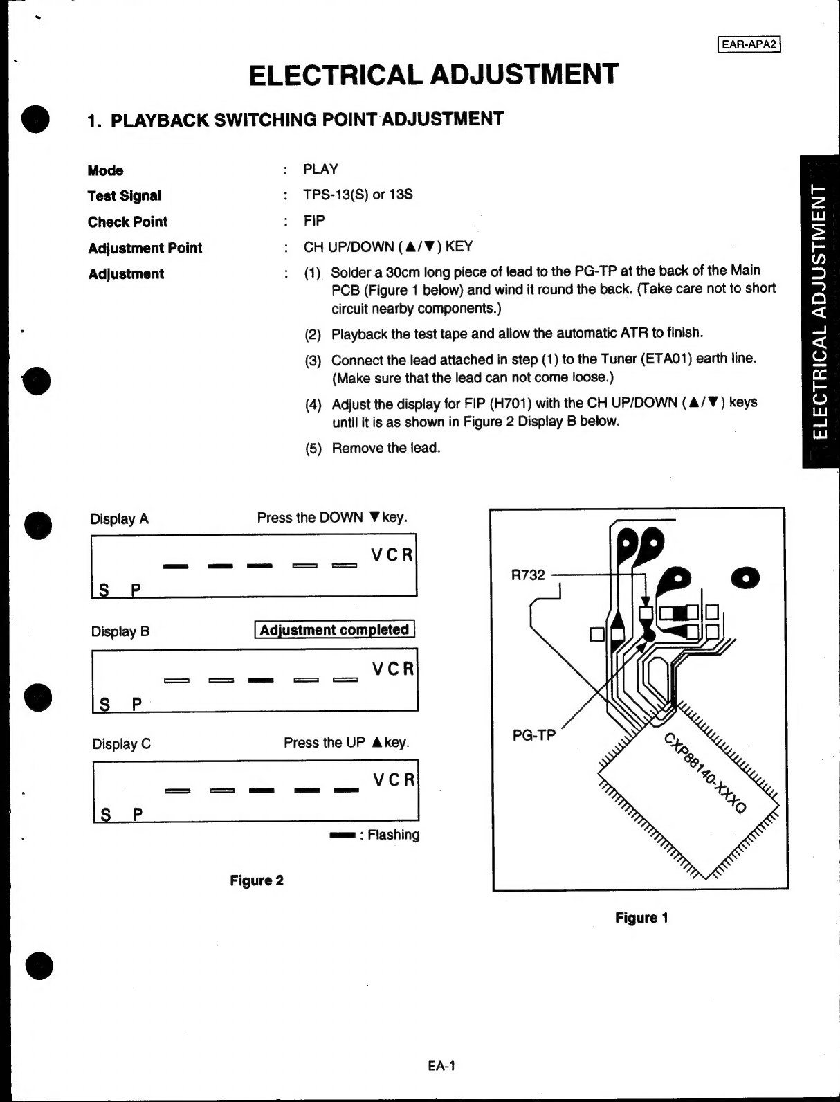
1.
PLAYBACK
SWITCHING
POINT
ADJUSTMENT
een
EA-1
MECHANICAL
ADJUSTMENT
...............................................................
MA-1
DECK
ADJUSTMENT
POINTS
ен
citer
tore
пони
dates
MA-1
1.
MECHANISM
CONTROL
..............
diiit
Qa
ke
nt
аниа
идэн
MA-2
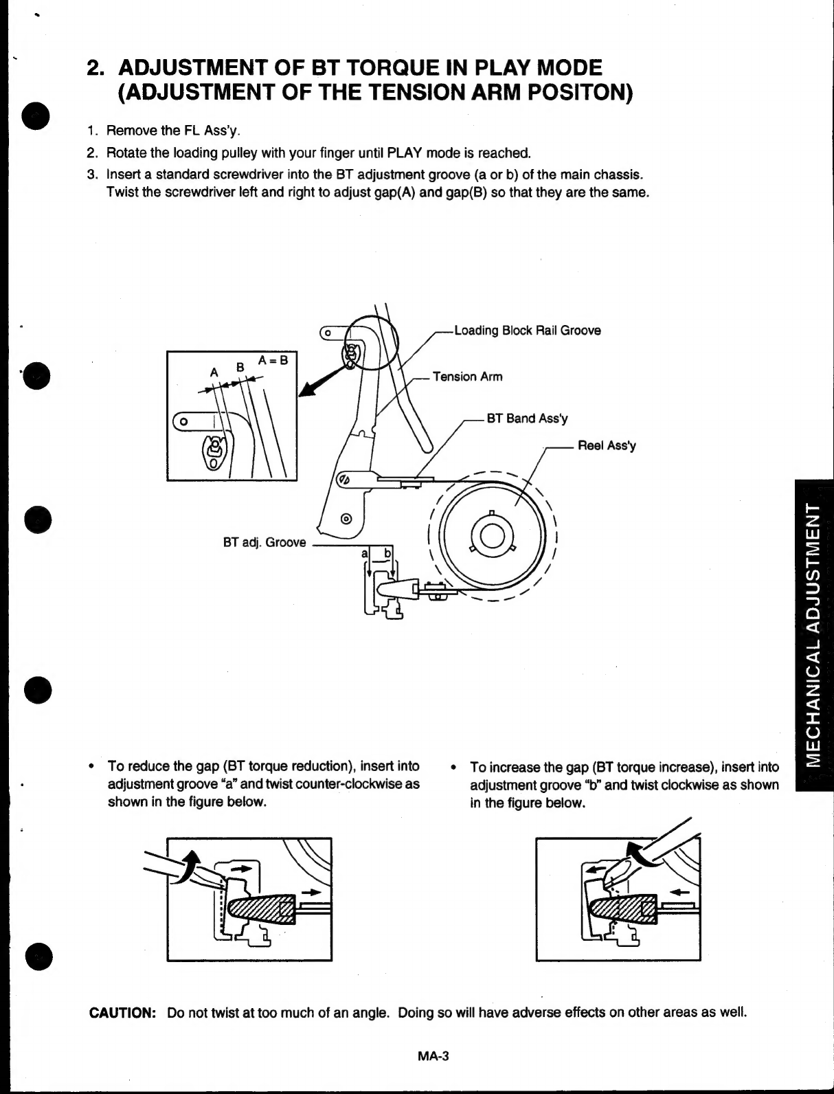
2.
ADJUSTMENT
OF
BT
TORQUE
IN
PLAY
MODE
een
MA-3
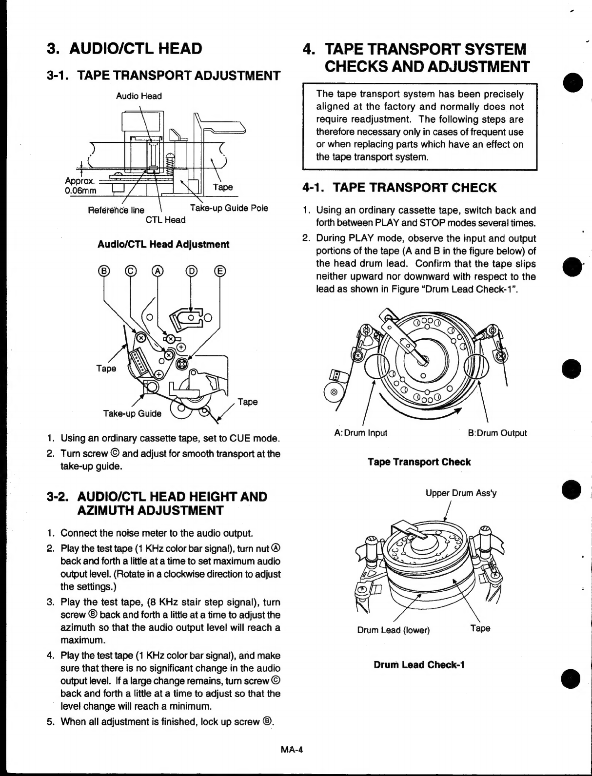
9;
AUDIOICTL
BEAD:
sisan
enn
A
ааа
a
sb
lina
oU
RR
рыны
Н
MA-4
4.
TAPE
TRANSPORT
SYSTEM
CHECKS
AND
ADJUSTMENT
линеен
MA-4
5.
INTERCHANGEABILITY
ADJUSTMENT
eee
MA-6
6.
FRONT
LOADING
ASSEMBLY
ATTACHMENT
ttt
MA-10
7.
RG
POST
HEIGHT
ADJUSTMENT................
a
eed
iibi
ides
MA-11
PERIODIC
МАНТЕНАМСЕ........
niono
den
pobe
Ia
ansa
ak
Vaska
MA-12
EXPLODED
VIEW
OF
THE
CASSETTE
DECK
MECHANISM
...............
enn
MA-14
MECHANICAL
PARTS
LIST
=
ssp
reat
ананы
арады
санан
онай
leko
une
MP-1
DIAGBAM
ана
as
омар
lena
o
dolar
e
ань
1
1:
BLOCK
DIAGRAM
D
——~~T„=———-—-E
ETE
M
1
2.
TERMINOLOGY
REFERENGES.
spiso
to
nalsnno
ының
ud
ya
a
omara
afa
2
3.
SCHEMATIC
DIAGRAM)
нанына
Sa
E
make
4
4.
1C,
TRANSISTOR
LEAD
IDENTIFICATION
encens
6
5.
"ELECTRICAL
PARTS
LOCATION
ix
an
and
Skol
и
ene
8
6.
REMOVAL
OF
THE
DECK
MECHANISM
eee
11
7;
BRIEF
SERVICE
INSTRUCTION
u
азанны
ое
не
12
8.
CABINET
EXPLODED
VIEW
аннан
KE
er
UU
iU
tima
ын
erii
tnt
13
8:
ELECTRICAL
PARTS
LIST:
muki
анални
cdd
eja
kaa
at
ta
ai
e
a
a
a
a
PL-1