TeachLogic Maxim III User manual

Classroom Audio System
Amplifier | Mixer | Receiver
Installation Manual
Maxim™
III

1
Welcome
Congratulations on the purchase of your new Maxim™ III
Sound Field system. You can be assured that the Maxim™
III fulfills all specifications and was produced to high quality
control standards.
TeachLogic incorporates the latest state of the art
technology, employs the most advanced manufacturing
methodology and uses only premium quality components to
assure many years of reliable performance. We appreciate
your confidence by your selection of our product. It is
TeachLogic’s intent to uphold that confidence by providing
factory assistance and dealer support. This manual will help
you learn to use and gain the maximum benefit of the
Maxim™ III system.
We hope you will take the time to review
this manual to familiarize yourself with
the product operation and features.
TeachLogic LLC
Longmont, Colorado USA
www.TeachLogic.com

2
Maxim
™
III
Introduction
Safety Instructions
Read Instructions
All safety and operation instructions should be
read before operating this TeachLogic product.
Retain Instructions
Safety and operating instructions should be
kept for future reference.
Water & Moisture
This product should not be operated near water.
Heat Environment
Do not subject this product to excessive heat
conditions.
Power Source
This product must be connected to an AC power
source per the voltage input specified and
marked on the power supply.
Do not insert any power cable not provided by
the manufacturer into the product. Long prongs
can penetrate inside electrical components or
current charging conductors.
Power Cord Caution
Power cable should be routed clear of
foot traffic and supported clear of kinking
or abrasion.
Object Protection
Locate the operating unit so it will not be
subjected to falling objects or water entry.
Internal Service
User should not attempt to service this product.
All internal service must be accomplished by a
qualified technician.
Electric Shock
Do not adapt or modify the AC power plug. Do
not remove thus lifting the earth ground
connection (3rd prong) or use power supply
without a connector to a 3-prong grounded
outlet.
Certifications
TeachLogic systems are manufactured using
lead-free processes and are free of materials
harmful to the environment. They conform to the
most stringent new European guidelines for
consumer products (RoHS).
CAUTION
Recycle—Do not dispose rechargeable batteries in
trash. It is unlawful to do so in numerous states. Go
Green. Save our resources and don’t contaminate.
Contact: Earth911.com
1-800-CLEANUP

3
Maxim
™
III
Introduction
System info
Date of Purchase
Model Number
Serial Number
Notes
Contact
If you should encounter an
unresolved issue, please contact the
TeachLogic customer service
department for further assistance.
760-631-7800 | support@teachtogic.com | teachlogic.com
Limited warranty
For full warranty details refer to teachlogic.com/warranty.

4
Maxim
™
III
Table of Contents
Contents
System Overview ........................................................................................................................5
System Diagram .........................................................................................................................6
Installation.................................................................................................................................7
Installation Planning....................................................................................................................7
Installation of Ceiling Sensor.......................................................................................................8
Installation of Speakers...............................................................................................................9
Integration ...............................................................................................................................10
Page Mute/Pass Through Integration...................................................................................10-11
Fire Alarm Input ........................................................................................................................12
RS-232 Feature ........................................................................................................................13
Security Alert Feature ..........................................................................................................14-15
Configuration ..........................................................................................................................16
Final Setup................................................................................................................................16
Trouble Shooting.......................................................................................................................17
System Specifications ..........................................................................................................18-19

5
Maxim
™
III
System Overview
Front of IMA-520 receiver/amplifier
1. Power Button/ “TL” Indicator LED
2. Channel A Microphone Volume Control
3. Channel B Connectivity Indicator LED
4. Channel B Microphone Volume Control
5. Channel B Connectivity Indicator LED
6. DVD Volume Control
7. Computer Input Volume Control
8. Aux Input Volume Control
9. MP3 Volume Control
10. MP3 Input Port (3.5 mm)
11. Lesson Capture Volume Control
12. Lesson Capture Output Port (3.5 mm)
Back of IMA-520 receiver/amplifier
1. Speaker Output
2. Fire Alarm Mute Input
3. Page Input
4. Page Sensitivity Control
5. Page Input Impedance Selector
6. ALS Output (3.5 mm) & Gain Control
7. Five Band Digital Equalizer
8. RS-232 Input & OFF/ON Switch
9. Security Alert Interface
10. Aux-Mic Input (3.5 mm) & Aux-Mic Input
Selector
11. Computer Input (3.5 mm) / Computer Anti-
Hum ON/OFF Switch
12. DVD Dual Mono Inputs (RCA)
13. Two IR Ceiling Sensor Inputs (RCA)
14. 5 Volt USB Output for BRC-60
15. Power Input: 19 V DC 3.4 A
1
2
3
4
5
6
7
8
9
11
10
12
1
3
2
4
5
6
7
8
9
10
11
12
13
14
15

Maxim
™
III
Installation
7

Maxim
™
III
Installation
8
Installation planning
1. Amplifier/Receiver:
Choose location that
supports accessibility
requirements and wiring
constraints for power,
speakers, ceiling sensor,
and audio devices
connecting to the
amplifier.
2. Ceiling Sensor: Locate in
the center of the ceiling;
maintain line of sight;
keep away from direct
light and electrical
interference.
3. Speakers: Mark location
for wall mount vs. ceiling
mount and confirm wiring
run to the amplifier.
Ensure speakers evenly
cover the listening area.
4. Integrations/Connections:
Confirm location of other
systems you plan to
connect to the amplifier
such as audio devices,
intercom connections, fire
alarm, noting how the
wiring needs to run.
5. Microphones/Charger:
Confirm microphone
charging location for daily
use/charging.
1
2
3
3
3
3
3
3
3
3
5

9
Maxim
™
III
Installation
Installation of Ceiling Sensor (ICS-55)
The ideal mounting location is in the center of the room's ceiling. The ideal installation is flush mounted on
a white, reflective ceiling like the acoustic drop-down style. This will ensure 360º coverage and will
minimize the transmission distance for more reliable performance.
Installation 1 – Attach to T-bar tail
Installation 2 – Concrete or Drywall Surface
Installation 3 – Wood Surface
FINAL STEP: Route sensor cable to amplifier and plug into one of the amplifier’s two sensor inputs. An
illuminated green LED will indicate that the sensor is receiving power from the amplifier.

10
Maxim
™
III
Installation
Connection of speakers
The IMA-520 has two channels of amplified audio, rated for a minimum 4-ohm speaker load (two 8-ohm
speakers each). There are two blue phoenix style speaker connectors on the back panel, each providing
two pairs of speaker terminals. The top connector provides connection to both channels as does the
bottom connector. Each is wired in parallel to the other as shown below. These are the acceptable wiring
methods. For speaker installation instructions, please refer to the installation manual included in the
speaker packaging.
ADVISORY: The speaker terminals A1 and A2 are internally wired in parallel. DO NOT connect more than two
8-ohm speakers to either or both terminals such that the total load is less than 4 ohms. The same hold true for
B1 and B2.

11
Maxim
™
III
Page Mute/Page Pass Through
Page Mute/Page Pass Through
System behavior for Page Mute
When a signal of adequate level (voltage) is sensed on the page mute input terminal, all other audio
inputs to the Maxim™ III are muted to allow the building-wide page to be heard. The muting is applied to
wireless microphones as well as computer, DVD, and all other line inputs.
Effective for shipments after 4/1/19 of new units; serial numbers beginning with A19 and later (letter or
number is A, B, C… and number is 19, 20, …). For older units see notes at the end of this section.
New units: A paging system may be connected to the Maxim™ III. The panel labeling is based on a 25-
volt paging input signal. The Page Input impedance selector has three labeled switch positions (based on
power draw at 25 V):
• 0.1 W DRAW (5000 Ω impedance)
• 1.0 W DRAW (620 Ω impedance)
• MUTE OFF
MUTE OFF disconnects the page input from the Maxim™ III. The other two settings select transformer
taps inside the Maxim™ III for the speakers connected to the top left and lower right connections. These
two connections are labeled A1 and A2 in Diagram A below.
New Models:
Switch Setting:
0.1 W DRAW
1 W DRAW
MUTE OFF
Impedance
5000 Ω
620 Ω
Open circuit
Power Draw at 25 V 0.1 W 1.0 W 0 W
Power Draw at 70 V
1.0 W
7.9 W
0 W
Older Models:
Switch Setting:
100 V
70 V
25 V
Impedance
5000 Ω
620 Ω
115Ω
Power Draw at 25V 0.1 W 1.0 W 5.3 W
Power Draw at 70V
1.0 W
7.9 W
42 W

12
Maxim
™
III
Page Mute/Page Pass Through
Connecting the system:
Before connecting, the installer is responsible for determining that the TeachLogic amplifier
impedance is compatible with the paging system.
1. Unplug the 2-pin green Phoenix connector
2. Connect the speaker cable from the paging system to the 2 pin Phoenix connector of the Page input
3. Reconnect the 2-pin green Phoenix connector
4. Determine the signal level of the paging system (25 v, 70 v, or 100 v)
5. Set the slide switch to the appropriate speaker level setting
6. With the TeachLogic amplifier turned ON, send a page to test the mute function.
7. Adjust the sensitivity control to ensure the Maxim™ III senses the page signal noting that some pages
with quiet voices will require greater sensitivity settings. The system will maintain its mute until about
11 seconds after the page signal falls below the threshold for sensing. Thereupon, the wireless mics
are unmuted, and other audio levels are ramped up gradually to their prior volume (before mute).
8. In the event of a loss of AC power, the TeachLogic amplifier will continue to pass the page on to two of
the speaker connections as outlined on the following Diagram A. Only the upper left and lower right
speaker outputs will pass page without power.
Diagram A
These two terminals (Channel A) are
provided the page audio.

13
Maxim
™
III
Fire Alarm Mute Input
Fire Alarm Mute Input
The 2-pin orange Phoenix connector labelled Fire Alarm
provides an emergency mute of the TeachLogic amplifier.
When interfaced to the fire alarm panel relay contact output,
all audio inputs (microphones, DVD, etc.) will MUTE. In the
event of a fire, this will help to lower the overall decibel levels
and help students and staff hear the audible fire alarm tones/
instruction within the classroom.
This feature requires a contact closure from the Fire Alarm
Panel and the TeachLogic terminal is for a normally open
connection.
When there is continuity between the terminals (closed
condition) muting will occur and will continue for 10-15
seconds after contacts are open.

14
Maxim
™
III
RS-232
RS-232 feature
The RS-232 feature allows the user to remotely operate the
line level media inputs via a separate wall panel controller.
The RS-232 connector is connected via three wires to the
back panel connector shown to the right.
This allows the receiver/amplifier to be placed in an area or
compartment that is not easily accessed by the user.
Codes that are required for this setup are available on the
teachlogic/com/resources page under “Application Notes” or
directly at https://TeachLogic.com/TeachLogic-app-notes-rs-
232-control/.
Audio levels very often need to be adjusted when switching
from computer audio to DVD players and other audio sources.
Such operations as level UP, DOWN and MUTE are easily
accomplished via a typical eight button controller. Shown here
is a Cables To Go controller.
Connecting the control panel:
Connect the control panel wires to the provided 3-pin Phoenix
connector.
Turn RS232 SWITCH to ON position. This will disable the
function of the input volume/gain control knobs on the front of
the amplifier.

15
Maxim
™
III
Security Alert Interface
Security Alert Feature
Effective for shipments after this date of new or reprogrammed units.
Serial numbers beginning with A19 and later (letter or number is A, B,
C… and number is 19, 20, …).The Maxim™ III security alert feature,
when triggered by an IRT-60 sapphire mic on Channel A, creates a
relay contact closure or opening. The back panel connection is a
normally closed and normally open terminal paired with the common
terminal as shown to the right.
Note: the wireless microphone channel B does not trigger security alert.
Pulse mode:
The Maxim™ III may be set to provide either 4- or 1-pulse signal at the relay. This new feature allows
the user to change from 1 to 4 pulses, or 4 to 1 pulse. Different monitoring systems may require one or
the other.
The steps below describe how to select either the 1-pulse or 4-pulse mode and how to
determine/confirm the Maxim™ III’s selected mode.
Ordinarily, the Maxim™ III will arrive new with the 4-pulse mode selected by default. Installers should
nevertheless confirm the mode upon installation if the security alert feature will be employed. Once set,
the mode is active and should remain set until such time as it is manually changed as detailed below.
The output on the amplifier is a three pin COM, N/O, N/C contact closure labeled “SECURITY ALERT”.
To check the mode:
Note the LED color on the power button at the TL logo.
• If power state is ON (Blue LED at power button), press once to set power state OFF (Red LED).
• If Red, then you may start the process.
1. Press and hold the power button (in Red state) for the entire process.
2. After 4 seconds, the LED will change colors.
3. Note the number of RED flashes AFTER the GREEN flash.
If one RED after GREEN, then mode is 1-pulse mode. (This will repeat 3 times.)
G R G R G R
If four RED after GREEN, then mode is 4-pulse mode. (This will occur 1 time.)
G R R R R
The important part of the sequence is the number of red flashes that follow one green flash.
4. Release the power button.

16
Maxim
™
III
Security Alert Interface
To change the mode:
Whether mode is 1-pulse or 4-pulse, the steps below will change it to the other mode.
1. If power state is ON (Blue LED at power button), press once to set power state OFF (Red LED). If Red,
then you may start the mode switching process.
2. Locate the RS-232 on/off switch on the back panel.
3. Press and hold the front panel power button (in Red state) for the duration of the mode switching
process. (Figure 3 below)
4. Move the RS-232 switch from ON to OFF and back again FIVE times. Then release the front panel
power button. (Figure 4 below)
The process requires 5 full cycles of the RS-232 switch while the power button in Red OFF state is held in.
Using the previous process, check the mode to confirm that the Maxim™ III is in the desired 1-pulse or 4-
pulse mode. If not, repeat the steps above to change the mode.
Press/hold power button
Cycle RS-232 Switch 5 times

17
Maxim
™
III
Final Setup
Final Setup
Now that the system is installed and connected, turn the system “ON” and test its performance.
The testing will be done using an IR Microphone (Sapphire™ or Handheld) to confirm good connectivity.
AMPLIFIER
• Connect power supply to amplifier, then plug into outlet.
• Turn the Maxim™ III ON by pushing the power button. The “TL” illuminates solid blue when the amplifier
is powered ON.
• Confirm there is power to the IR ceiling sensor: A green LED on edge of sensor should be illuminated
that indicates it is receiving power.
• Set all gain/volume dials to mid scale (12 o’clock position)
IRT-60 (SAPPHIRE) MICROPHONE SETUP
• Confirm "Ch A" volume dial is at mid scale (12 o’clock position)
• Slide gain/volume control switch on Sapphire to "Normal" setting.
• Press and hold power mic button until the LED light illuminates.
• Observe Sapphire power LED. Solid blue indicates power is on and mic is transmitting.
• Observe amplifier Ch A indicator LED. It should be green, indicating a connection between the
microphone and ceiling sensor.
• If using two IRT-60 microphones in the same room, one must be changed to channel B to avoid
interference. Watch the how-to video on teachlogic.com/resources.
Note: Next steps are best performed with a second person as the listener
• Stand under or in front of a speaker.
• Hold the microphone with the top at your collarbone and observe the speaker volume in the room by
speaking in a natural voice.
• Raise the volume on Ch A until feedback begins, then reduce volume to an acceptable level and until
indications of feedback have stopped.
• Walk around the room while talking into microphone to confirm good connectivity and sound levels and
lack of feedback under/in front of each speaker.
IRH-35 HANDHELD MICROPHONE SETUP
• Confirm "Ch B" volume control is set to mid-scale (12 o’clock position)
• Power on microphone using ON/OFF switch.
• Observe LED above mic switch. Solid green indicates power is on and ready to use.
• Observe amplifier Ch B indicator LED. It should be green, indicating a connection between the
microphone and IR ceiling sensor.
• Hold the microphone about 3 inches from the mouth, above chin level and perform voice test.
• Raise the volume on “Ch B” until feedback begins, then reduce volume to eliminate all feedback.
• Walk around the room while talking into the microphone to confirm good connectivity and sound
under/in front of each speaker without feedback.
Once complete, charge microphones so they are ready for use.

18
Maxim
™
III
Troubleshooting
Troubleshooting
Problem
Solution
System will not power “ON” Verify AC power; the power button will illuminate to Blue when turned ON
Check if system has been unplugged; reconnect to power outlet or
use another device to ascertain power available at outlet
Check circuit breaker
Call maintenance for assistance
System is turned “ON” but there
is no sound
or
System is in standby and does
not “wake up”
Turn “ON” microphone/ transmitter; the power button will illuminate to Blue
when turned ON
If the power button is illuminated red, the battery is low
Ensure the mic is not muted (blinking light indicates it is muted)
Ensure gain/volume control knob on amplifier/receiver is turned up to
mid scale (12 o’clock position)
On amplifier/receiver, ensure a green LED is illuminated just below Ch
A or Ch B knob (depending on the microphone used).
If no LED is illuminated:
•Check the green LED on the ceiling sensor
If sensor LED is not lit:
•Sensor has been disconnected, or
•Power output to sensor has failed (Sensor or amplifier may need to
be replaced)
Voice is distorted and/or signal
drop-out occurs
Verify that the sensor is not being covered
Verify there is no obstruction between microphone and sensor
Ensure there is no direct sunlight on sensor
Ensure no other IR mics in room are turned on
If sensor is mounted on a dark surface or without a flush ceiling surface,
reception can be hampered.
Contact
If your problem persists and this guide has not resolved the issue, contact our customer service department
for additional assistance. (760) 631-7800 | support@TeachLogic.com

Maxim
™
III
Specifications
18
Maxim™ III (IMA-520) specs
Receiver Input
Infrared FM, 2 wireless mic channels
Modulation
Wide-band FM
Reception Frequencies
Ch. A: 2.08 MHz | Ch. B: 2.54 MHz
Deviation
10 kHz Nominal, 25 kHz Maximum
De-emphasis
50 µs
Tone Signal
32.768 kHz
Infrared Wavelength
850 nm
External Sensor Input
2, RCA, powered ports
Connectivity Coverage
1,600 sq ft per sensor, up to 2 sensors supported
Total Harmonic Distortion
<1% @ 1 kHz
Frequency Response
20 H - 20 kHz, ± 3 dB
Aux line level Inputs
4: 1 dual RCA, 3.5mm
Anti-hum balun
present on 1 Aux input for computer
Wired Mic input
1 aux input switchable to mic input
Line Output
Lesson Capture: 3.5 mm with gain control - front panel
ALS: 3.5 mm with gain control - rear panel
Page Input
2-pin Phoenix; 25 V or 70 V normal
Page Input Sensitivity
3.6 V min
Security Alert
Contact closure (COM, N/O, N/C)
Fire Alarm
Contact closure by fire panel mutes audio
Amplifier Output Power
50 W RMS, 2 x 25 W channels
Output Impedance
4 Ω minimum
Equalization
5-band, ±12 dB
S/N Ratio
›65 dB
Speaker Connection
4-pin Phoenix connectors
Charger Output
5 V DC, USB
Power Supply
19 V DC / 6.3 A; CE, CSA and UL listed
Dimensions
8.5” W x 1.75” H x 7.5” D
Weight
2 lb 4 oz
Power Supply (AC-36) specs
Type
Regulated Switching Power Supply
Input Voltage
100-240 volts AV, 47-63 Hz
Output Voltage
19 volts DC, 3.43 A
Power Output
65 watts max.

Maxim
™
III
Specifications
19
Sapphire (IRT-60) microphone/transmitter specs
Transmission Carrier
Infrared
Transmission Frequencies
2.08 MHz & 2.54 MHz
Channel Selection
Field Switchable
Transmitting Diodes
Six
Wavelength
850 nm
Modulation
FM Wide-Band
Frequency Response
100 Hz - 10 KHz
Pilotone Frequency
32.768 KHz
Peak Deviation
± 25 KHz
Dynamic Range
95.5 dB @ 2.8% THD
Operating Range
60 Ft. line of sight
Latency (mic to speakers)
0.87 ms
Battery Used
Lithium-ion polymer (3.7V / 620mAh)
Battery Life
8 Hrs/Charge
External Power Charger
5V DC Micro USB Connector
Transmission Angle
180° Conical
User Controls
Power (On/Off)
Press & Hold
Mute Switch (On/Off)
Momentary Press (blinks when muted)
Addt’l Mic Gain Control
Normal, -3dB, -6dB
Audio Source Vol./Gain
Increase, Decrease
Channel Select
(A or B) in battery compartment
External Mic/Aux Input
3.5 mm Line Level
Dimensions (H x W x D)
3.5” x 1.25” x 0.75”
Weight
1.4 oz including battery
Handheld (IRT-35) microphone/transmitter specs
Transmission Carrier
Infrared
Transmission Frequencies
2.08 MHz & 2.54 MHz
Channel Selection
Field Switchable
Transmitting Diodes
Ten
Wavelength
850 nm
Modulation
FM Wide-Band
Pilotone Frequency
32.768 KHz
Peak Deviation
± 25 KHz
Operating Range
50 ft. line of sight
Power Switch (Slide)
On/Off
Battery Charge Level (LED)
Green: Full | Orange: Medium | Red: Low
Battery Life
Approx. 7 Hr./Charge
Dimensions
2.125” dia. (Head), 1.4375” dia. (Body), 9.625” H
Weight
10.3 oz. w/ Battery
Other manuals for Maxim III
2
This manual suits for next models
1
Table of contents
Other TeachLogic Stereo System manuals
TeachLogic
TeachLogic Matrix User manual
TeachLogic
TeachLogic Spectrum IMA-840 User manual
TeachLogic
TeachLogic Maxim IRM-6650 User manual

TeachLogic
TeachLogic Maxim II User manual
TeachLogic
TeachLogic Maxim IMA-540 User manual

TeachLogic
TeachLogic QUANTUM II User manual

TeachLogic
TeachLogic Maxim II User manual

TeachLogic
TeachLogic QUANTUM II User manual
TeachLogic
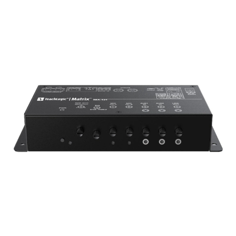
TeachLogic Matrix IMA-121 User manual

TeachLogic
TeachLogic Maxim III User manual

