TeamOne TeaM1-5GM User manual

Page 1 | 64
TM1-5GM2020SG
TeaM1-5GM Modem/Router
TM1-5GM2020SG
USER GUIDE
Revision 6.0
Updated 30 Mar 2022

Page 2 | 64
TM1-5GM2020SG
Purchase list of TeaM1-5GM modem/router & accessories
1. Harsh Environment Package 1 (TeaM1-5GM-H1)
SN
Description
Quantity
Part No.
Photo
Remarks
1.1 TeaM1-5GM
Modem/Router Unit 1 TM1-
5GM2020SG
1.2 Power cable 1 5GM-H1-B
Length 1m with
open ended
1.3 IO cable
(Serial ports, DIOs) 1 5GM-H2-B
Length 1m with
open ended
1.4
Integrated 3G, 4G,
5G and GNSS
antenna (IP69K)
1
5GM-ANT-
M670-BB-
6CG
Cable length
4.5m

Page 3 | 64
TM1-5GM2020SG
2. Harsh Environment Package 2 (TeaM1-5GM-H2)
SN
Description
Quantity
Part No.
Photo
Remarks
2.1 TeaM1-5GM
Modem/Router Unit 1 TM1-
5GM2020SG
2.2 Power cable 1 5GM-H1-B
Length 1m with
open ended
2.3 IO cable
(Serial ports, DIOs) 1 5GM-H2-B
Length 1m with
open ended
2.4
Low-Profile integrated
3G, 4G, 5G and
GNSS antenna
(IP69K)
1
5GM-ANT-
M970-BB-
6CG
Cable length
4.5m

Page 4 | 64
TM1-5GM2020SG
3. Basic Package (TeaM1-5GM-B)
SN
Description
Quantity
Part No.
Photo
Remarks
3.1 TeaM1-5GM
Modem/Router Unit 1 TM1-
5GM2020SG
3.2 Power cable 1 5GM-H1-B
Length 1m with
open ended
3.3 IO cable
(Serial ports, DIOs) 1 5GM-H2-B
Length 1m with
open ended
3.4
Integrated 3G, 4G,
5G antenna (IP67) 1 5GM-ANT-
YB0007AA
Cable length
0.5m
3.5
4G and 5G antenna
(IP67) 2
5GM-ANT-
GSA.8835
or
5G-ANT2-
YE0003AA-B
or
Cable length 1m
or direct
connection with
SMA terminal
3.6 IP67 GNSS active
antenna 1
5GM-ANT -
GNSS -
YLY001CA
Cable length 1m
and SMA
terminal

Page 5 | 64
TM1-5GM2020SG
4. Optional & Customized Accessories
SN
Description
Part No.
Remark
4.1 Power cable 5GM-H1-C-XX
XX: customization code issued.
Customized length and/or termination available
4.2 IO cable 5GM-H2-C-XX
XX: Customization code issued.
Customized length and/or termination available
4.3 IP67 Cat.5e/6 Ethernet
cable 5GM-H3-C-XX
Options:
Cable length with IP67
shielded cable and mounting.
4.4 IP67, USB2.0HS cable 5GM-H4-XX
Options:
Cable length with IP67
shielded cable and mounting.
Please contact supplier for customization of functions and accessories

Page 6 | 64
TM1-5GM2020SG
Read this Safety Guide first.
User's Manual - Safety Guide
Thank you for purchasing this 5G Modem Router.
WARNING • Before using, read these user's manuals of this 5G modem router to ensure
correct usage through understanding. After reading, store them in a safe place for future reference.
Incorrect handling of this product could possibly result in personal injury or physical damage. The
manufacturer assumes no responsibility for any damage caused by mishandling that is beyond
normal usage defined in these manuals of this modem router.
NOTE
• The information in this manual is subject to change without notice.
• The manufacturer assumes no responsibility for any errors that may appear in this manual.
• The reproduction, transmission or use of this document or contents is not permitted without express
written authority.
About The Symbols
Various symbols are used in this manual, the user’s manual and on the product itself to ensure correct
usage, to prevent danger to the user and others, and to prevent property damage. The meanings of
these symbols are described below. It is important that you read these descriptions thoroughly and
fully understand the contents.
WARNING
This symbol indicates information that, if ignored, could possibly result in
personal injury or even death due to incorrect handling.
CAUTION
This symbol indicates information that, if ignored, could result possibly in
personal injury or physical damage due to incorrect handling.
Typical Symbols
This symbol indicates an additional warning (including cautions). An illustration is
provided to clarify the contents.
This symbol indicates a prohibited action. The contents will be clearly indicated in an
illustration or nearby (the symbol to the left indicates that disassembly is prohibited).

Page 7 | 64
TM1-5GM2020SG
Safety Precautions
WARNING
Never use the 5G modem router if a problem should occur.
Abnormal operations such as smoke, strange odor, excessive sound, damaged casing
or elements or cables, penetration of liquids or foreign matter or the like can cause a
fire or electrical shock. In such cases, immediately turn off the power and then
disconnect the power plug from the power outlet. After making sure that the smoke or
odor has stopped, contact your dealer. Never attempt to make repairs yourself
because this could be dangerous.
• The power outlet should be close to the 5G modem router and easily accessible.
Never disassemble and modify.
The product contains high voltage components. Modification and/or disassembly of
the product could result in fire, electrical shock, or injury to skin.
• Never open the cabinet.
• Ask your dealer to repair and clean insider.
Do not place the 5G modem router on an unstable surface.
If the 5G modem router should be dropped, it could result in an injury, and continued
use could result in fire or electrical shock.
• Do not place the 5G modem router on an unstable, slanted or vibrant surface such
as a wobbly or inclined stand.
• Use the caster brakes placing the 5G modem router on a stand with casters.
• Do not place the 5G modem router in the side up position, the lens up position or the
lens down position.
• In the case of a ceiling installation or the like, contact your dealer before installation.
Use only the correct power cable and the correct power outlet.
Incorrect power supply could result in fire or electrical shock.
• Use only the correct input power depending on the indication on the 5G modem router
and the safety standard.
Be cautious of the power cable connection.
Incorrect connection of the power cable could result in fire or electrical shock.
• Do not touch the power cable with a wet hand.
• Check that the connecting portion of the power cable is clean (with no dust), before
using. Use a soft and dry cloth to clean the power plug.
• Insert the power plug into a power outlet firmly. Avoid using a loose, unsound outlet
or contact failure.

Page 8 | 64
TM1-5GM2020SG
SIMPLIFIED EU DECLARATION OF CONFORMITY
The simplified EU declaration of conformity referred to in Article 10(9) shall be provided as follows:
Hereby, TEAM ONE TECHNOLOGIES PTE LTD declares that the radio equipment type TM1-
5GM2020SG is in compliance with Directive 2014/53/EU. The full text of the EU declaration of
conformity is available at the following internet address: https://www.teamone.com.sg/product/the-5g-
modem/.

Page 9 | 64
TM1-5GM2020SG
Version History
Version
No. Date Description
01
10.02.2021
Initial copy
02
15.03.2021
Document layout changes
03
23/04/2021
Document information updates
04
14/07/2021
Includes antennas information
05
20/01/2022
Includes safety information and CE DoC
05 30/03/2022
Web GUI layout changes, includes firmware upgrade procedure
(section 6.7) and RF module AT command information (section 6.3)

Page 10 | 64
TM1-5GM2020SG
Table of Contents
1Overview.................................................................................................................................13
1.1 Cellular Network Connection ............................................................................................13
1.2 Protocols and Data Security .............................................................................................13
1.3 Characteristic and Features..............................................................................................13
2Installation Guide and Connection ...........................................................................................14
2.1 Dimensions / Size / Mounting Holes ..................................................................................14
2.2 Panels / External Connectors............................................................................................15
2.3 Panel LEDs.......................................................................................................................16
2.4 Antenna Frequency Bands Information.............................................................................16
2.5 External Cables and Connector Pin Assignment ...............................................................17
2.5.1 Panel Connector J1 and External Cable H1...............................................................17
2.5.2 Panel Connector J2 and External Cable H2...............................................................18
2.5.3 Panel Connector J3 and External Cable H3...............................................................19
2.5.4 Panel Connector J4 and External Cable H4...............................................................19
2.6 SIM Card Plug / Removal..................................................................................................20
3System Power Up & Setup ......................................................................................................21
3.1 Connection Diagram .........................................................................................................21
3.2 Power Up..........................................................................................................................21
4General Web Portal Settings....................................................................................................22
4.1 Log Into Your Router Running OpenWrt............................................................................22
4.2 Status Page ......................................................................................................................23
4.3 Network and Graphs .........................................................................................................24
4.3.1 Load ..........................................................................................................................24
4.3.2 Traffic.........................................................................................................................24
4.3.3 Connection ................................................................................................................25
4.4 Device List ........................................................................................................................25
5Status......................................................................................................................................26
5.1 Firewall .............................................................................................................................26
5.2 Routes..............................................................................................................................26
5.3 Logs .................................................................................................................................27
6Administration .........................................................................................................................28
6.1 Set Up Root Password......................................................................................................28
6.2 SSH – Access ...................................................................................................................28
6.2.1 Access the Modem Operating System Using SSH.....................................................29
6.2.2 Access RF Module AT Command With SSH..............................................................30

Page 11 | 64
TM1-5GM2020SG
6.3 SSH-Keys.........................................................................................................................32
6.4 System .............................................................................................................................32
6.4.1 General Settings........................................................................................................32
6.4.2 Logging......................................................................................................................32
6.4.3 Time Synchronization ................................................................................................33
6.4.4 Language and Style...................................................................................................34
6.5 Software ...........................................................................................................................34
6.6 LED Configuration ............................................................................................................35
6.7 Backup / Flash Firmware ..................................................................................................35
6.8 Reboot..............................................................................................................................37
7Configuration...........................................................................................................................37
7.1 banIP................................................................................................................................37
7.1.1 banIP Configuration Options......................................................................................38
7.1.2 Logging of Banned Packets .......................................................................................39
7.2Cellular .............................................................................................................................40
7.2.1 Interval ......................................................................................................................40
7.2.2 LED Configuration for Signal Strength .......................................................................42
7.2.3 Mode .........................................................................................................................42
7.3 RemoteGPIO....................................................................................................................43
7.4 uHTTPd ............................................................................................................................44
7.4.1 Features ....................................................................................................................44
7.4.2 Configuration .............................................................................................................45
7.5 SerOverNet ......................................................................................................................45
7.5.1 Overview ...................................................................................................................45
7.5.2 List of Ports ...............................................................................................................46
7.5.3 Net.............................................................................................................................46
7.5.4 Links..........................................................................................................................48
7.6 SNMPD ............................................................................................................................49
8Network...................................................................................................................................50
8.1 Interfaces..........................................................................................................................50
8.1.1 LAN Interface.............................................................................................................50
8.1.2 WAN ..........................................................................................................................53
8.2 DHCP and DNS................................................................................................................54
8.3 Static Routes ....................................................................................................................54
8.4 Firewall .............................................................................................................................54
8.4.1 General Setting..........................................................................................................55

Page 12 | 64
TM1-5GM2020SG
8.4.2 Port Forward..............................................................................................................55
8.4.3 Traffic Rules ..............................................................................................................56
8.4.4 NAT Rules .................................................................................................................57
9Statistics .................................................................................................................................58
9.1 Processor .........................................................................................................................58
9.2 System Load.....................................................................................................................58
9.3 Memory ............................................................................................................................59
10 Logout.....................................................................................................................................59
11 Appendix.................................................................................................................................60
11.1 Optional Enterprise 5G/4G+GNSS Integrated RF Antenna (IP69K) ..............................60
11.2 Optional Low Profile 5G/4G+GNSS Integrated RF Antenna (IP69K) .............................61
11.2.1 Mounting option for M670 and M970 .........................................................................62
11.3 Optional Heavy Duty 5G/4G+GNSS Integrated RF Antenna (IP69K) ............................63
11.4 Optional Heavy Duty 5G/4G+GNSS Integrated RF Antenna (IP69K) ............................64
Table 1: Panel Connectors .............................................................................................................15
Table 2: Panel Connectors and External Cable ..............................................................................17
Table 3: Panel Connectors J1 and External Cable H1 ....................................................................17
Table 4: Panel Connectors J2 and External Cable H2 ....................................................................18
Table 5: Panel Connectors J3 and External Cable H3 ....................................................................19
Table 6: Panel Connectors J4 and External Cable H4 ....................................................................19

Page 13 | 64
TM1-5GM2020SG
1 Overview
TeaM1-5GM is an industrial standard 5G modem to support 3G, 4G, 5GNR and GNSS. The
robust mechanical enclosure design of modem/router makes it suitable to operate in harsh
environment. Powered by 9~48V DC power supply, the device is suitable for vehicle, train,
maritime, railway and outdoor applications.
1.1 Cellular Network Connection
TeaM1-5GM is able to provide connection
between local devices and the internet
through mobile 3G/4G/5GNR (Sub-6GHz)
network supported by mobile ISP. The device
is able to connect to a 5GNR Sub- 6GHz
network by default in either SA or NSA mode.
In the case of the field that does not have
5G coverage from specific ISP or cellular
network signal quality is not good enough to
support essential data connection, the device
will automatically fallback to 3G/4G
connection. 5G network shall have the priority
to be used when the device is within the area
of co-existing 3G/4G/5G network coverage.
1.2 Protocols and Data Security
Connection with 2x pre-configured destination
IP address could be established upon powered
on. Device authentication and data encryption
using appropriate Transport Layer Security
(TLS/SSL) cryptographic protocol shall be
implied between device/remote site operating
over the cellular network.
1.3 Characteristic and Features
Frequency Band
5GNR bands:
•n41/ n77/ n78/ n79
4G-LTE bands:
•LTE: B1/ 3/ 5/ 7/ 8/ 18/ 19/ 20/ 28/ 32/
34/ 38/ 39/ 40/ 41/ 42/ 43
Characteristic and Key Features
•CPU AM5715
•OpenWrt Operating system Firewall
•GNSS
•Data Logger 4 x MIMO
•Delay 2 - 5ms
•TCP/UDP/FTP/HTTP
•UL: 200 Mbps
•DL: 1.0 Gbps
Interface
•1x Ethernet
•1x USB 2.0 HS
•2x RS232
•1x RS485
•1x RS422
•4x Discrete Input 4x Discrete output
•1x USB2.0 Engineering port
Page 14 | 64
TM1-5GM2020SG
2 Installation Guide and Connection
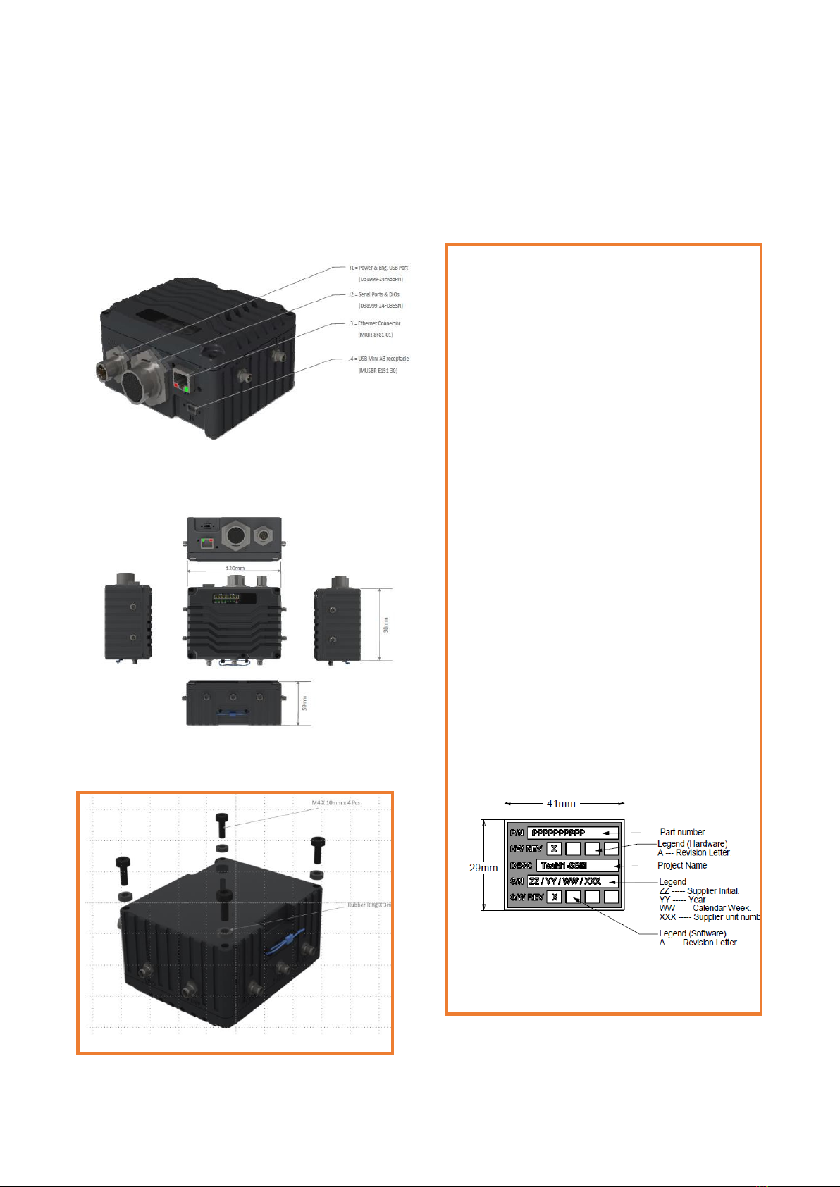
2.1 Dimensions / Size / Mounting Holes
Size: 120mm x 98mm x 59mm
Weight: 600g
Vibration: 10g-PK random
Shock: 20g impulse
Waterproof: IP67
Surface: AL6061, Black anodizing
Mounting: 4 x M4 x 10mm screw mounting
Product Serial Tag:

Page 15 | 64
TM1-5GM2020SG
2.2 Panels / External Connectors
Table 1: Panel Connectors
SN
Description
Remarks
ANT3
5G Antenna 1, SMA 50 Ω
4x4 MIMO, N77/78/79
5GNR
ANT4
5G Antenna 2, SMA 50 Ω
ANT5
5G Antenna 3, SMA 50 Ω
ANT6
5G Antenna 4, SMA 50 Ω
ANT1
4G/3G Antenna 1, SMA 50 Ω
ANT2
4G/3G Antenna 2, SMA 50 Ω
GNSS
GNSS antenna
Passive/active antenna
J1
Power input, engineering port,
D38999/24WA6PN
Optional accessory:
external cable H1
J2
2xRS232, 1xRS422, 1x RS485, 4x DI, 4x DO
ports, D38999/24WD35SN
Optional accessory:
external cable H2
J3
1x Gigabit Ethernet LAN. RJ45 (ruggedized),
MRJR-8F81-01
Optional accessory:
external cable H3
J4
Portal connector USB2.0 HS.
Mini-USB-AB, MUSBR-E151-30
Optional VLAN connection.
GP
4x M4 x 10mm screw, Ground point.
Connect to earth
SIM
SIM card cover, 2x M3 x 10mm screw, with rubber
gasket.
For IP67 sealing.
Nano-SIM.

Page 16 | 64
TM1-5GM2020SG
2.3 Panel LEDs
2.4 Antenna Frequency Bands Information
Above table shows the operating band in the TeaM1-5GM. Any 50 Ohm RF antenna working in the
bands shall be applicable for the device. The TeaM1-5GM uses SMA socket on its panel, and the
respective antennas shall be terminated with SMA plug accordingly. The maximum transmission
RF power from the device is illustrated as in table below.
The antennas selected shall be complaint with above power rating requirements. For CA bands,
see document Quectel_RG50xQ_Series_CA&EN-DC_Features. Optional antennas refer to
Appendix.
4G Signal Strength and Connectivity
5G Signal Strength and Connectivity
LEDs
ON
ON
ON
ON
LEDs
ON
ON
ON
ON
Status
Connected
Weak
Medium
Strong
Status
Connected
Weak
Medium
Strong
GNSS LED:
ON ---
GNSS connected
Flashing --- Searching
Power LED: On -- Operating
Flashing -- error
LAN LED:
On — LAN connected
SRL LED:
On -- Operating
WAN LED:
On — WAN connected
USB LED:
On — USB portal connected
SA LED:
On — 5GNR SA connected
NSA LED:
On — 5GNR NSA connected

Page 17 | 64
TM1-5GM2020SG
2.5 External Cables and Connector Pin Assignment
External panel connectors used on TeaM1-5GM are listed as in below table:
Table 2: Panel Connectors and External Cable
Panel Connector
Description and part number
External cable and terminal connector PN.
J1
Power input, engineering port,
D38999/24WA6PN
Optional accessory: external cable H1
Connector: D38999/26WA6SN
J2
2xRS232, 1xRS422, 1x
RS485,
4x DI, 4x DO ports,
D38999/24WD35SN
Optional accessory: external cable H2
Connector: D38999/26WD35PN
J3
1x Gigabit Ethernet LAN.
RJ45
(ruggedized), MRJR-8F81-01
Optional accessory: external cable H3
RJ45 plug (optional accessories if necessary)
J4
Portal connector USB2.0 HS.
Mini-USB-AB,
MUSBR-E151-30
Optional VLAN connection. (Offline or online)
Connector Mini-USB-AB plug.
2.5.1 Panel Connector J1 and External Cable H1
Table 3: Panel Connectors J1 and External Cable H1
Panel Connector
Signal Description
Cable connector
Cable labelling
J1: D38999/24WA35PN
D38999/26WA35SN
Pin No.
Description
Pin No.
Pin 1
9~48V power in
>
16W peak.
9~48V power in Vin+
Pin 1
1 (RED)
Pin 2
Power Ground Vin-
Pin 2
2 (Black)
Pin 3
Engineering
USB2.0 p
ort
(
Optional device)
USB _DGND
Pin 3
3 (Optional)
Pin 4
USB_D-
Pin 4
4 (Optional)
Pin 5
USB_D+
Pin 5
5 (Optional)
Pin 6
USB_VBUS
Pin 6
6 (Optional)

Page 18 | 64
TM1-5GM2020SG
2.5.2 Panel Connector J2 and External Cable H2
Table 4: Panel Connectors J2 and External Cable H2
Panel Connector
Signal Description
Cable connector
Cable
labelling
J2: D38999/24WD35SN
D38999/26WD35PN
Pin No.
Pin No.
Pin 1
RS422
connection
from
TeaM1- 5GM
RS422A (RX+)
Pin 1
1
Pin 2
RS422B (RX-)
Pin 2
2
Pin 4
RS422Z (TX-)
Pin 4
4
Pin 5
RS422Y (TX+)
Pin 5
5
Pin 18
RS485 connection
RS485A (D+)
Pin 18
18
Pin 19
RS485B (D-)
Pin 19
19
Pin 20
RS232-1 connection
from TeaM1- 5GM
DGND
Pin 20
20
Pin 21
RS232-1-TXD
Pin 21
21
Pin 22
RS232-1-RXD
Pin 22
22
Pin 23
RS232-2 connection
from TeaM1- 5GM
DGND
Pin 23
23
Pin 24
RS232-2-TXD
Pin 24
24
Pin 25
RS232-2-RXD
Pin 25
25
Pin 26
DGND
Pin 26
26
Pin 27
DGND
Pin 27
27
Pin 28
Discrete input.
VIH > 6V
VIL < 4V
9~48V.
Input 0
Pin 28
28
Pin 29
Input 1
Pin 29
29
Pin 32
Input 2
Pin 32
32
Pin 33
Input 3
Pin 33
33
Pin 30
DGND
Pin 30
30
Pin 31
DGND
Pin 31
31
Pin 34
DGND
Pin 34
34
Pin 7
OD output from
TeaM1
5GM.
Max. Current:
0.5A @ 48V
Vout_L1
Pin 7
7
Pin 9
Vout_L2
Pin 9
9
Pin 11
Vout_L3
Pin 11
11
Pin 13
Vout_L4
Pin 13 13
Pin 6
+5VDC @0.1A output
Pin 6
6
Pin 8
+12VDC @0.2A output
Pin 8
8
Pin 10
+3.3VDC @0.1A output
Pin 10
10
Pin 12
[email protected] output
(Power supply input)
Pin 12 12
Pin 14*
Optional.
LVCMOS3.3V
output.
*Do not connect.
** Contact supplier i
f
required
WARN_EXT2, warning signal
Pin 14
14
Pin 15*
Data_safety_Ext, data safety
warning signal
Pin 15 15
Pin 16*
HB_EXT, heart-beating
signal, device health condition
Pin 16 16
Pin 17*
Warn_EXT1, warning signal
Pin 17
17
*** Please contact supplier if customized cable is required, with specific termination and length.

Page 19 | 64
TM1-5GM2020SG
2.5.3 Panel Connector J3 and External Cable H3
Table 5: Panel Connectors J3 and External Cable H3
Panel Connector
Signal Description
Cable connector
Cable labelling
J3: MRJR-8F81-01
RJ45 plug
Pin No. Pin No.
Pin 1
Gigabit
Ethernet
connection.
Cat.5e or Cat.6
cable.
BI_DA+
Pin 1
Whit/green
Pin 2
BI_DA-
Pin 2
Green
Pin 3
BI_DB+
Pin 3
White/Orange
Pin 4
BI_DC+
Pin 4
Blue
Pin 5
BI_DC-
Pin 5
White/Blue
Pin 6
BI_DB-
Pin 6
Orange
Pin 7
BI_DD+
Pin 7
White/Brown
Pin 8
BI_DD-
Pin 8
Brown
*RJ45
water-proo
f
accessory avai
lable up
on
reques
t.
2.5.4 Panel Connector J4 and External Cable H4
Table 6: Panel Connectors J4 and External Cable H4
Panel Connector
Signal Description
Cable connector
Cable labelling
J3: MUSBR-E151-30
Mini-USB-AB plug
Pin No.
Pin No.
Pin 1
USB c
able
USB_VBUS
Pin 1
Pin 2
USB_D-
Pin 2
Pin 3
USB_D+
Pin 3
Pin 4
USB_DGND
Pin 4
*Mini-USB waterproof
accessory available
upon request.

Page 20 | 64
TM1-5GM2020SG
2.6 SIM Card Plug / Removal
1.Untighten the two screws on SIM card
cover
2. Using needle to eject the SIM card out
from the Connector.
3. Insert the Nano-SIM card into the SIM
card connector
Notes: SIM card cover shall be put back
with sealing gasket
This manual suits for next models
1
Table of contents
Popular Modem manuals by other brands


T-Mobile
T-Mobile W'n'W Stick IV user manual

Paradyne
Paradyne Hotwire 6390 installation instructions

Paradise Datacom
Paradise Datacom P300 Series Installation & operating handbook

Bellwave
Bellwave BSM-856 user manual

Telstra
Telstra TURBO Getting started guide

CML Microcircuits
CML Microcircuits CMX866 manual