Tech1 VERSA PATROL User manual

VERSA PATROL SERVICE MANUAL
0
VERSA PATROL SERVICE MANUAL
Contents
1. Foreword.............................................................................................................................................23
2. Document Revision.............................................................................................................................34
3. Radio Information...............................................................................................................................45
4. Package Layout ...................................................................................................................................46
4.1 Box Dimension ............................................................................................................................46
4.2 Box Layout...................................................................................................................................47
5. Parts of the Radio................................................................................................................................48
6. Initial Assembly and Preparation........................................................................................................49
6.1 Charging ......................................................................................................................................49
6.2 Battery Pack ..............................................................................................................................510
6.3 Antenna.....................................................................................................................................611
6.4 Belt Clip.....................................................................................................................................711
6.5 Earpiece (Optional) ...................................................................................................................712
7. Basic Operation.................................................................................................................................913
7.1 Power on and Adjust volume knob...........................................................................................913
7.2 Channel selector knob ..............................................................................................................913
7.3 PTT button...............................................................................................................................1014
7.4 Monitor button .......................................................................................................................1014
8. Features ..........................................................................................................................................1115
8.1 Voice Prompt ..........................................................................................................................1115
8.2 CTCSS/DCS...............................................................................................................................1115
8.3 Channel Scan...........................................................................................................................1115
8.4 Time-Out-Timer (TOT).............................................................................................................1115
8.5 Low Power Alarm....................................................................................................................1115
8.6 Squelch Level Adjustment.......................................................................................................1115
8.7 High/Low Power Selection......................................................................................................1115

VERSA PATROL SERVICE MANUAL
1
8.8 Wireless cloning..........................................................................................................................11
8.9 Cable cloning...............................................................................................................................11
8.10 VOX Function ..............................................................................................................................11
8.11 Emergency Alarm........................................................................................................................11
8.12 Channel Keylock..........................................................................................................................11
8.13 Dual Watch Operation ................................................................................................................11
9. Radio Assembly and Disassembly.......................................................................................................12
9.1 Assembly and Disassembly .........................................................................................................12
9.2 Exploded View............................................................................................................................. 18
10. Quality Check ..................................................................................................................................19
10.1 Physical Appearance ...................................................................................................................19
10.2 RF Testing....................................................................................................................................19
10.3 Battery and Charger....................................................................................................................19
10.4 Radio Check.................................................................................................................................19
11. Schematic Diagram .........................................................................................................................20
12. Block Diagram .................................................................................................................................22
10.1 Front Board .....................................................................................................................................22
10.2 Back Board ......................................................................................................................................23
13. Troubleshooting and Repair..................................................................................................................23
13.1 External Parts..................................................................................................................................23
13.2 Internal Parts...................................................................................................................................24
14. Reprogramming ....................................................................................................................................25
14.1. Initial Setup ....................................................................................................................................25
14.1.1. General Requirements............................................................................................................25
14.1.2. How to install Quicktalk Pro programming software..............................................................25
14.1.3. Install Prolific USB to Serial Comm Port..................................................................................28
14.2. Radio Programming .......................................................................................................................30

VERSA PATROL SERVICE MANUAL
2
1. Foreword
SCOPE OF THIS MANUAL
This manual is intended for use by experienced technicians
familiar with similar types of commercial grade communications
equipment. It contains all the required service information for the
equipment and current released data.
NOTE BEFORE USING
-DO NOT transmit until all RF connectors are verified secure and
any open connectors are properly terminated.
-SHUT OFF and DO NOT operate this equipment near electric
detonator caps or in an explosive atmosphere.
-This equipment should be serviced by a qualified technician
only.
VERSA PATROL SERVICE MANUAL
3
2. Document Revision
DOCUMENTED BY
DESCRIPTION
DATE
Winston Yves L. Esguerra
Initial Release
December 2019

VERSA PATROL SERVICE MANUAL
4
3. Radio Information
4. Package Layout
4.1 Box Dimension
4.2 Box Layout
5. Parts of the Radio
6. Initial Assembly and Preparation
6.1 Charging
Before charging the battery, make sure that the transceiver has been turned OFF. To charge
the battery, plug in to AC outlet (110-240Vac) and insert the bottom of the battery into the
charger. Red LED light on the charger indicates that the battery is charging. Green LED light
indicates that the battery is fully charged. The battery reaches its maximum capacity after 2 to 3
charging cycles.

VERSA PATROL SERVICE MANUAL
5
-Connect adaptor to charger then plug in to AC outlet 100V-240VAC
-Insert battery to the charger. 2 ways of charging,with transceiver or battery only.
Note: The battery may be charged either attached or removed from the transceiver. Never charge
the battery at temperature below -10°C (14°F) or above 35°C (95°F).
6.2 Battery Pack
To Attach: Fit the battery at the back of the transceiver and slide the battery. Click sound
indicates that the battery is locked.

VERSA PATROL SERVICE MANUAL
6
To Remove: Make sure the radio is turned OFF. Press down the battery latch at the bottom of
the transceiver then pull the battery.
6.3 Antenna
Connect the antenna to the antenna connector then turn the antenna clockwise to install and
turn counterclockwise to remove antenna.

VERSA PATROL SERVICE MANUAL
7
6.4 Belt Clip
Fit the belt clip at the back of the transceiver. Screw the belt clip.
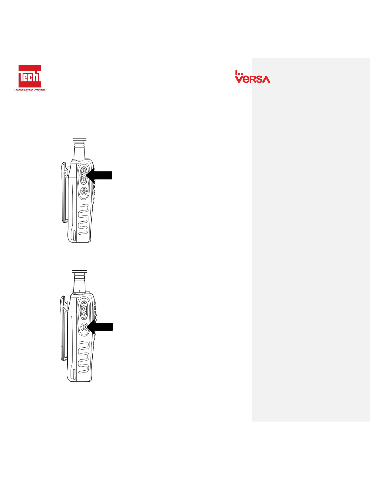
6.5 Earpiece (Optional)
Open the earmic cover located at the left side of the transceiver.

VERSA PATROL SERVICE MANUAL
8
Connect Earpiece.
VERSA PATROL SERVICE MANUAL
9
7. Basic Operation
7.1 Power on and Adjust volume knob
- Turn the Power/ Volume knob clockwise. Beep sound indicates that the power is on.
- To adjust the sound, Press MON and rotate the Power/ Volume to desired level.
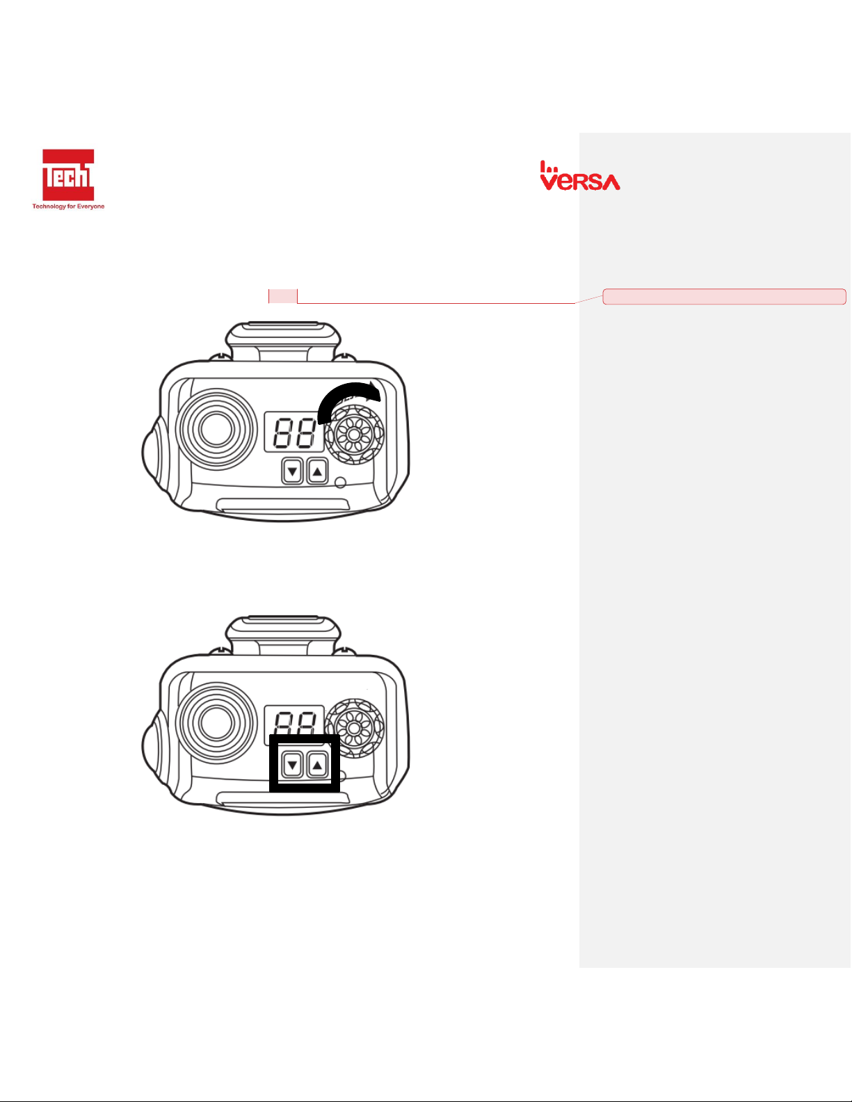
7.2 Channel selector knob
- Press Up and Down button to choose desired channel. Up to 99 Channels.
Commented [MSG1]: Please show where MON is.
VERSA PATROL SERVICE MANUAL
10
7.3 PTT button
- To make a call, Press PTT. Keep mouth 3-4cm away from mic when speaking.
- Release PTT button to receive signals.
- Light Indicator: Steady Red when Transmitting / Steady Green when Receiving.
7.4 Monitor button
- When pressed, the CTCSS/DCS Code is disabled.

VERSA PATROL SERVICE MANUAL
11
8. Features
8.1 Voice Prompt
-Voice prompting when selecting channel.
8.2 CTCSS/DCS
-Reduces the interference by adding a low frequency.
8.3 Channel Scan
-Scan Channel 1 to 99.
8.4 Time-Out-Timer (TOT)
-Limit the transmission period 0 to 300 seconds.
8.5 Low Power Alarm
-Audio prompt when the battery is low.
8.6 Squelch Level Adjustment
-Adjust the receiver sensitivity.
8.7 High/Low Power Selection
-Adjust the output power of the radio to 1W or 5W.
8.8 Wireless cloning
-Copy program of a patrol radio to another unit wireless.
8.9 Cable cloning
-Copy program of a patrol radio to another unit using cloning cable.
8.10 VOX Function
-Enable transmission without pressing the PTT button.
8.11 Emergency Alarm
-Broadcast loud alert tone in case of emergency.
8.12 Channel Keylock
-Lock display channel.
8.13 Dual Watch Operation
- Scan channel 16 and 1 selected channel.

VERSA PATROL SERVICE MANUAL
12
9. Radio Assembly and Disassembly
9.1 Assembly and Disassembly
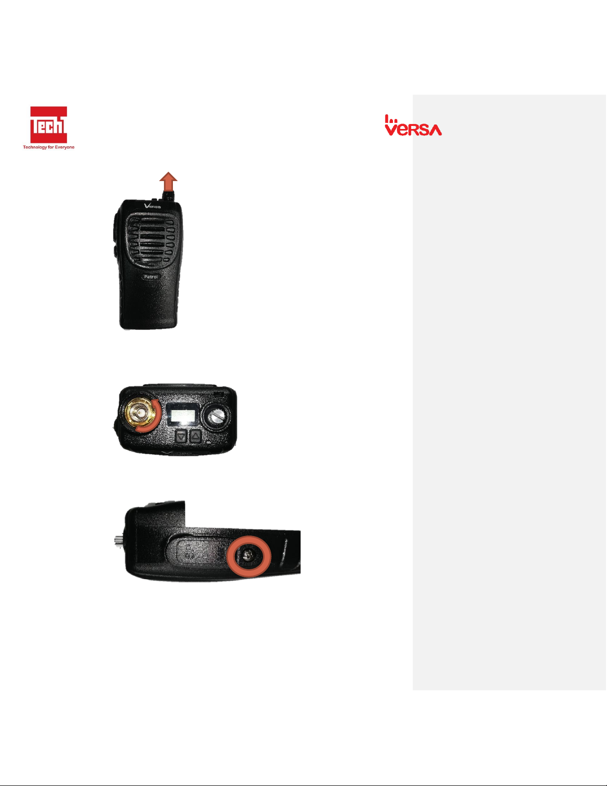
1. Remove antenna. Turn antenna counterclockwise.
2. Remove belt clip. Unscrew belt clip, turn counterclockwise to remove.
3. Remove the battery. Press down the battery latch at the bottom of the transceiver then
pull the battery.
VERSA PATROL SERVICE MANUAL
13
4. Remove Power/ Volume Knob. Pull the knob.
5. Remove antenna round nut screw. Using round nut screwdriver, turn counterclockwise
to remove.
6. Remove earmic cover. Unscrew by turning counterclockwise.
VERSA PATROL SERVICE MANUAL
14
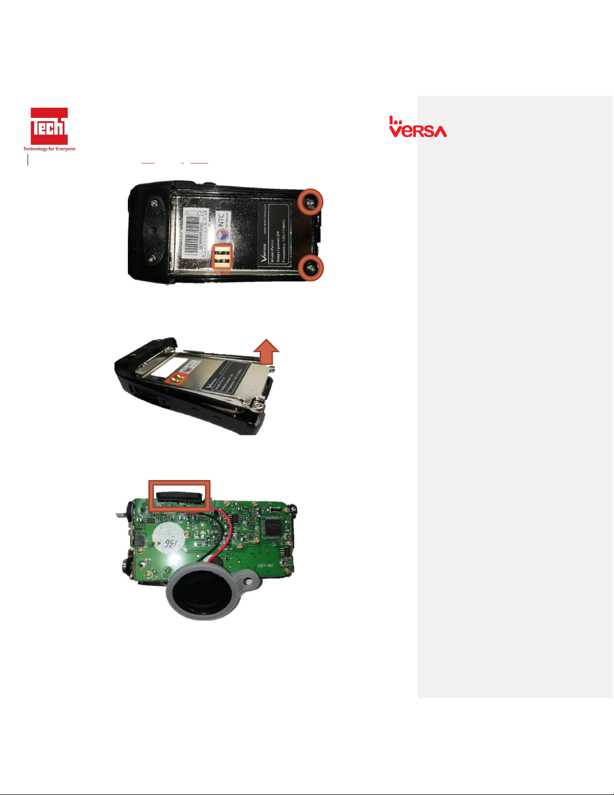
7. Remove the 2 screwson the metal body. Unscrew by turning counterclockwise.
8. Remove metal body from the housing. Pull up the metal body using chassis remover.
9. Remove earmic rubber.
VERSA PATROL SERVICE MANUAL
15
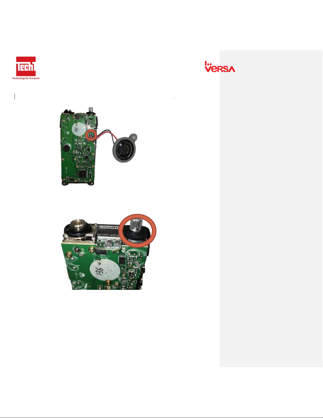
10. Remove speaker and mic wire to the board. Using soldering iron,de-solder the wire.
11. Remove Potentiometer nut screw rubber cover. Pull the black rubber.

VERSA PATROL SERVICE MANUAL
16
12. Remove Potentiometer nut screw. Using a wrench,turn counterclockwise to remove
nut.
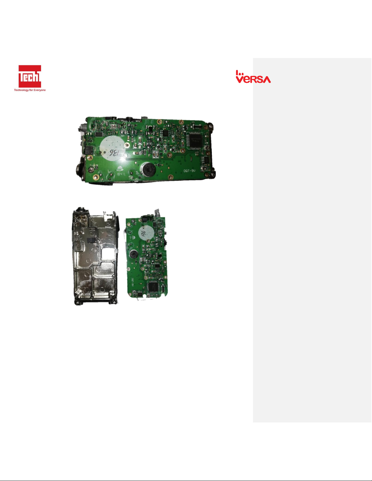
13. Remove screw from the board. Turn counterclockwise to unscrew. (11 screws)
VERSA PATROL SERVICE MANUAL
17
14. Remove the antenna connector by de-soldering it from the mainboard of the
transceiver.
15. Pull mainboard to the metal body.
VERSA PATROL SERVICE MANUAL
18
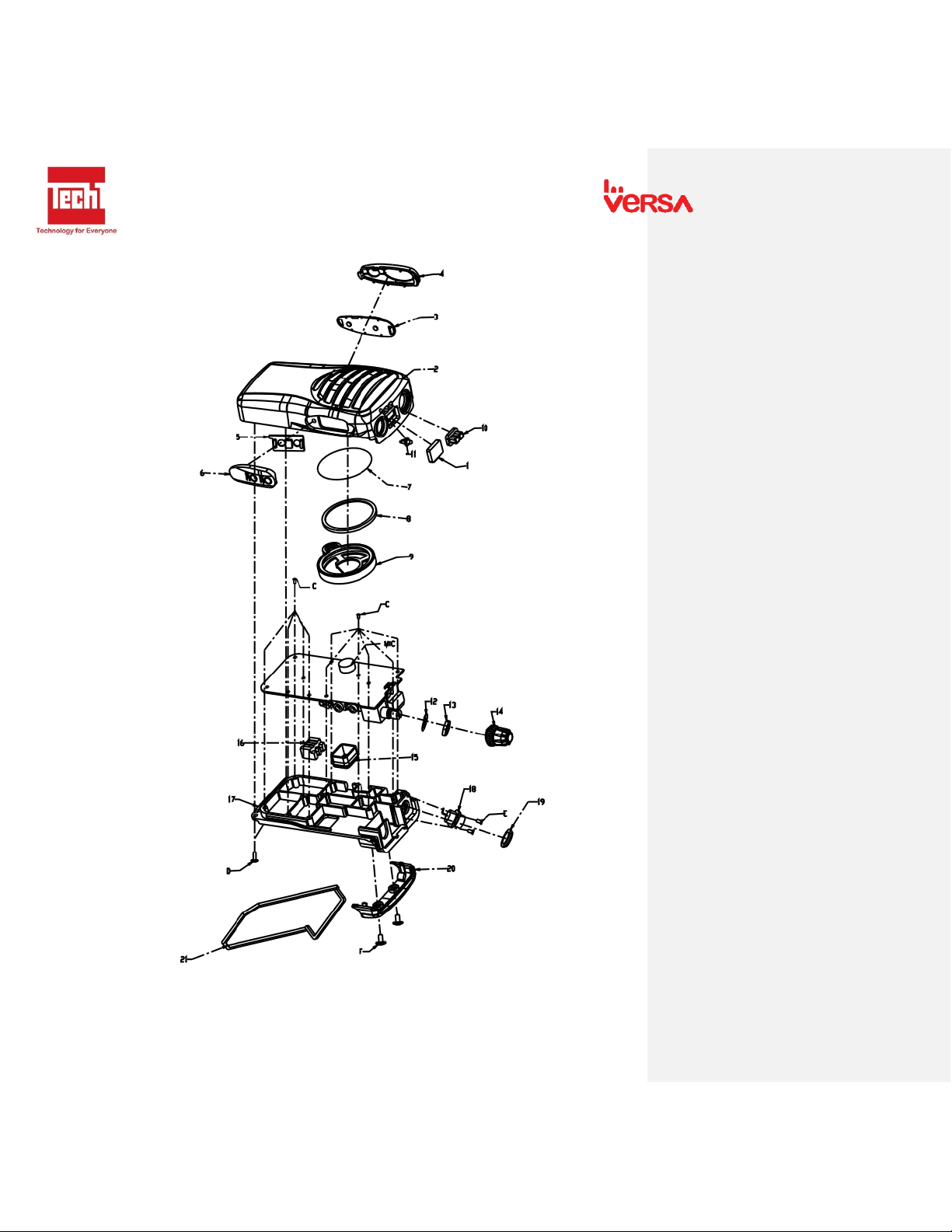
9.2 Exploded View
VERSA PATROL SERVICE MANUAL
19
10. Quality Check
10.1 Physical Appearance
-Check physical appearance of the radio.
-Housing
-Knobs
-Battery Charger
-Belt clip
-Buttons
-Antenna
10.2 RF Testing
-Measure maximum and minimum receive sensitivity, TX power and VSWR
Test: Maximum and Minimum RX sensitivity, TX power and VSWR
Test Objective: The purpose of this test is to verify if the RX sensitivity, TX power and VSWR is
within the specifications.
Preliminary Steps:
For Receive: Set the frequency of the Signal Generator to the center frequency of Radio.
For Transmit: Set the maximum output power of the radio to the wattmeter.
RECEIVE
FREQUENCY
SENSITIVITY
REMARKS
MAX
MIN
TRANSMIT
FREQUENCY
TX POWER
VXWR
REMARKS
10.3 Battery and Charger
Test: Battery and Charger Voltage Measurement
Test Objective: The purpose of this test is to verify if the battery and charger voltage is within the
specifications.
Preliminary Steps:
For Battery: Set the battery specification to the battery analyzer.
For Charger: Set the multi-tester to Vdc.
OHMTEST
VOLTAGE
REMARKS
BATTERY
ADAPTOR
CHARGER
REMARKS
CHARGER
10.4 Radio Check
-Test short range communication
Table of contents
Popular Two-way Radio manuals by other brands


Radio Shack
Radio Shack 60-3067 owner's manual

Digitalk
Digitalk 2 - WAY COMMUNICATOR Owner's Manual and Operating Instructions

Oricom
Oricom UHF2100 manual

Cobra
Cobra MICROTALK CXR800C owner's manual

Motorola solutions
Motorola solutions APX 6000XE 3.5 user guide

Motorola
Motorola Professional CDM1550 LS+ Detailed service manual