TechNexion TEK3-BSW User manual
TEK3-BSW BOX PC PRODUCT MANUAL
(TEK3-BSW)
VER. 1.00
April 15, 2019

TEK3-BSW HARDWARE MANUAL –VER 1.00 APR 15 2019
Page 2of 37
REVISION HISTORY
Revision
Date
Originator
Notes
1.00
April 15, 2019
TechNexion
First public release

TEK3-BSW HARDWARE MANUAL –VER 1.00 APR 15 2019
Page 3of 37
TABLE OF CONTENTS
1. Introduction ...............................................................................................................................................5
1.1. General Care and Maintenance .........................................................................................................5
2. TEK3-BSW Product Overview ..................................................................................................................6
2.1. Functional Block Diagram ..................................................................................................................6
2.2. Dimensions.........................................................................................................................................7
2.3. External Connectors...........................................................................................................................8
2.4. Internal Board Connectors .................................................................................................................9
2.4.1. Galvanic Isolated (TEK3-xxxxx-Rxx-Lxxx-xxx-xxxx-XG21-xxxx-xxxx)........................................9
2.4.2. Non-Galvanic Isolated (TEK3-xxxxx-Rxx-Lxxx-xxx-xxxx-XS21-xxxx-xxxx)...............................10
2.4.3. Board View Without the Power, I/O Expansion and SO-DIMM Modules ..................................11
3. External Connectors................................................................................................................................12
3.1. USB Host Connectors ......................................................................................................................12
3.2. HDMI (High Definition Multi-Media Interface) Connector.................................................................12
3.3. miniDP (Mini DisplayPort) Connector...............................................................................................12
3.4. USB OTG (Type-C) Connector ........................................................................................................13
3.5. Gigabit Ethernet Interface (LAN1/LAN2)..........................................................................................13
3.6. Audio Connectors.............................................................................................................................14
3.7. Power Input Connector.....................................................................................................................14
3.8. PWR Button......................................................................................................................................14
3.9. RST Button.......................................................................................................................................14
3.10. Micro-SIM Connector......................................................................................................................14
3.11. MicroSD Connector........................................................................................................................15
3.12. LED Light Indicators.......................................................................................................................15
3.13. Antenna Holes................................................................................................................................15
3.14. Galvanic Isolated Connectors (TEK3-xxxxx-Rxx-Lxxx-xxx-xxxx-XG21-xxxx-xxxx) (optional).......16
3.14.1. Galvanic Isolated Digital I/O Connectors (GPIO1/GPIO2) (optional)......................................17
3.14.2. Galvanic Isolated Serial Port (RS-XXX) (optional) ..................................................................18
3.15. Non-Galvanic Isolated Connectors (TEK3-xxxxx-Rxx-Lxxx-xxx-xxxx-XS21-xxxx-xxxx) (optional)19
3.15.1. Non-Galvanic Isolated Digital I/O Connectors (GPIO1/GPIO2) (optional) ..............................20
3.15.2. Non-Galvanic Isolated Serial Port (RS-XXX) (optional)...........................................................21
4. Internal Connectors and Expansion Options ..........................................................................................22
4.1. CMOS Jumper..................................................................................................................................22
4.2. RTC Battery Connector....................................................................................................................23
4.3. SO-DIMM DDR3L Slot......................................................................................................................23
4.4. M.2 KEY-E Slot.................................................................................................................................23
4.5. M.2 KEY-B Slot.................................................................................................................................23

TEK3-BSW HARDWARE MANUAL –VER 1.00 APR 15 2019
Page 4of 37
5. BIOS Setup .............................................................................................................................................24
5.1. Entering and Exiting BIOS................................................................................................................24
5.2. BIOS Setup Screens Overview ........................................................................................................24
5.2.1. Main ...........................................................................................................................................25
5.2.2. Chipset.......................................................................................................................................26
5.2.3. Advanced...................................................................................................................................27
5.2.4. Boot............................................................................................................................................30
5.2.5. Security......................................................................................................................................31
5.2.6. Save & Exit ................................................................................................................................32
6. Mounting..................................................................................................................................................33
6.1. Surface Mounting .............................................................................................................................33
6.2. DIN Mounting....................................................................................................................................33
7. Ordering Information...............................................................................................................................34
7.1. Custom Part Number Rule ...............................................................................................................34
7.2. Standard Package Contents ............................................................................................................35
8. Important Notice......................................................................................................................................36
9. Disclaimer ...............................................................................................................................................37

TEK3-BSW HARDWARE MANUAL –VER 1.00 APR 15 2019
Page 5of 37
1. Introduction
1.1. General Care and Maintenance
Your device is a product of superior design and craftsmanship and should be treated with care.
The following suggestions will help you.
•Keep the device dry. Precipitation, humidity, and all types of liquids or moisture can contain
minerals that will corrode electronic circuits. If your device does get wet, allow it to dry completely.
•Do not use or store the device in dusty or dirty areas. Its parts and electronic components can be
damaged.
•Do not store the device in hot areas. High temperatures can shorten the life of electronic devices,
damage batteries, and warp or melt certain plastics.
•Do not store the device in cold areas. When the device returns to its normal temperature,
moisture can form inside the device and damage electronic circuit boards.
•Do not open the device while power is on. Otherwise electrical shock may result.
•Do not drop, knock, or shake the device. Rough handling can break internal circuit boards and
fine mechanics.
•Do not use harsh chemicals, cleaning solvents, or strong detergents to clean the device.
•Do not paint the device. Paint can clog the parts and prevent proper operation.
•Unauthorized modifications or attachments could damage the device and may violate regulations
governing radio devices.
These suggestions apply equally to your device, battery, charger, or any enhancement. If any device is
not working properly, take it to the nearest authorized service facility for service.
Regulatory information
Disposal of Waste Equipment by Users in Private Household in the European Union
This symbol on the product or on its packaging indicates that this product must not be
disposed of with your other household waste. Instead, it is your responsibility to dispose
of your waste equipment by handing it over to a designated collection point for the
recycling of waste electrical and electronic equipment. The separate collection and
recycling of your waste equipment at the time of disposal will help to conserve natural
resources and ensure that it is recycled in a manner that protects human health and the
environment. For more information about where you can drop off your waste equipment
for recycling, please contact your local city office, your household waste disposal service or the shop
where you purchased the product.
We hereby declare that the product is in compliance with the essential requirements and
other relevant provisions of European Directive 1999/5/EC (radio equipment and
telecommunications terminal equipment Directive).
TEK3-BSW HARDWARE MANUAL –VER 1.00 APR 15 2019
Page 6of 37
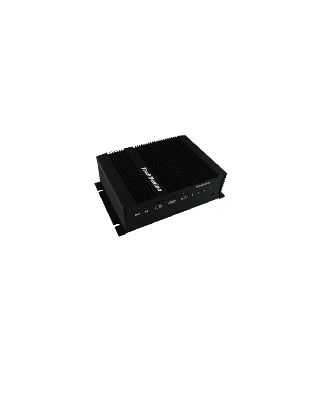
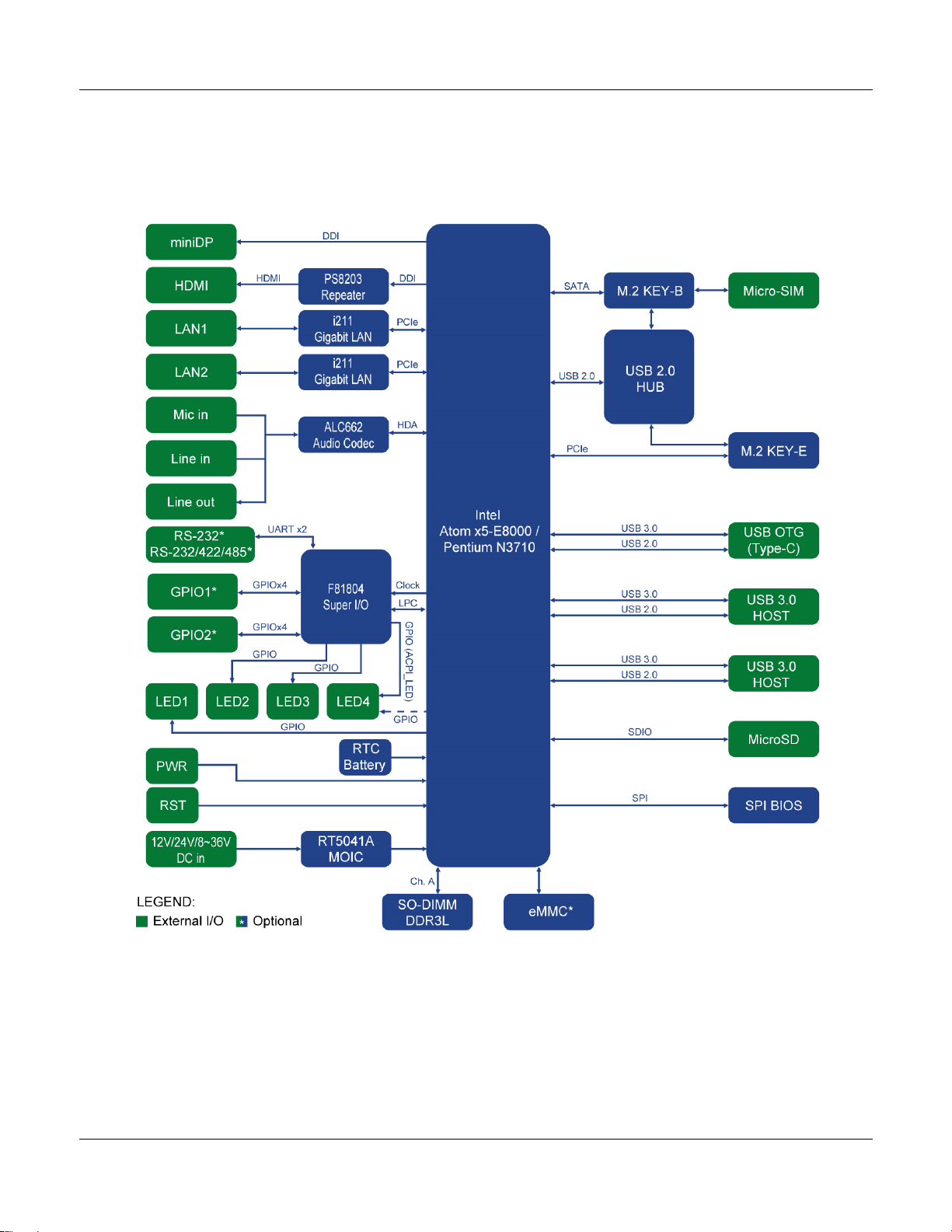
2. TEK3-BSW Product Overview
2.1. Functional Block Diagram

TEK3-BSW HARDWARE MANUAL –VER 1.00 APR 15 2019
Page 7of 37
2.2. Dimensions
The following figure shows the TEK3-BSW dimensions (unit: mm):

TEK3-BSW HARDWARE MANUAL –VER 1.00 APR 15 2019
Page 8of 37
2.3. External Connectors
The TEK3-BSW has a number of external connectors.
Front view:
1 3 4 5 6 7 8 9
2
10 11 12 13 14
Rear view:
15 16 17 18 19 20 21 22
23 24 25 26
External Connectors:
No.
Description
No.
Description
1
USB Host connector
14
RS-XXX (Serial Port) connector (optional)
2
USB Host connector
15
Power button
3
HDMI connector
16
Reset button
4
miniDP connector
17
Micro-SIM cardslot
5
USB OTG (Type-C) connector
18
MicroSD cardslot
6
LAN2 RJ45 connector
19
LED Light 1 indicator
7
3.5mm jack Line out
20
LED Light 2 indicator
8
3.5mm jack Line in
21
LED Light 3 indicator
9
3.5mm jack Mic in
22
LED Light 4 indicator
10
Power Input connector
23
Antenna hole
11
LAN1 RJ45 connector
24
Antenna hole
12
GPIO1 connector (optional)
25
Antenna hole
13
GPIO2 connector (optional)
26
Antenna hole

TEK3-BSW HARDWARE MANUAL –VER 1.00 APR 15 2019
Page 9of 37
2.4. Internal Board Connectors
The TEK3-BSW has several connectors, switches and internal expansion options.
2.4.1. Galvanic Isolated (TEK3-xxxxx-Rxx-Lxxx-xxx-xxxx-XG21-xxxx-xxxx)
Rear view (opened device) with the galvanic isolated I/0 Expansion and Power Expansion modules:
A B C
D
I/O Expansion Module Power Expansion
E Module
No.
Description
No.
Description
A
CMOS jumper
D*
SW1 DIP switch
B
RTC Battery connector
E*
SW3 Terminator Resistor DIP switch
C
SO-DIMM DDR3L slot
NOTE: Items marked with * are available on the galvanic isolated I/O Expansion module
(TXB-I2-GS2-GG8) (optional).

TEK3-BSW HARDWARE MANUAL –VER 1.00 APR 15 2019
Page 10 of 37
2.4.2. Non-Galvanic Isolated (TEK3-xxxxx-Rxx-Lxxx-xxx-xxxx-XS21-xxxx-xxxx)
Rear view (opened device) with the non-galvanic isolated I/0 Expansion and Power Expansion modules:
A B C
I/O Expansion Module Power Expansion
Module
No.
Description
No.
Description
A
CMOS jumper
C
SO-DIMM DDR3L slot
B
RTC Battery connector
TEK3-BSW HARDWARE MANUAL –VER 1.00 APR 15 2019
Page 11 of 37
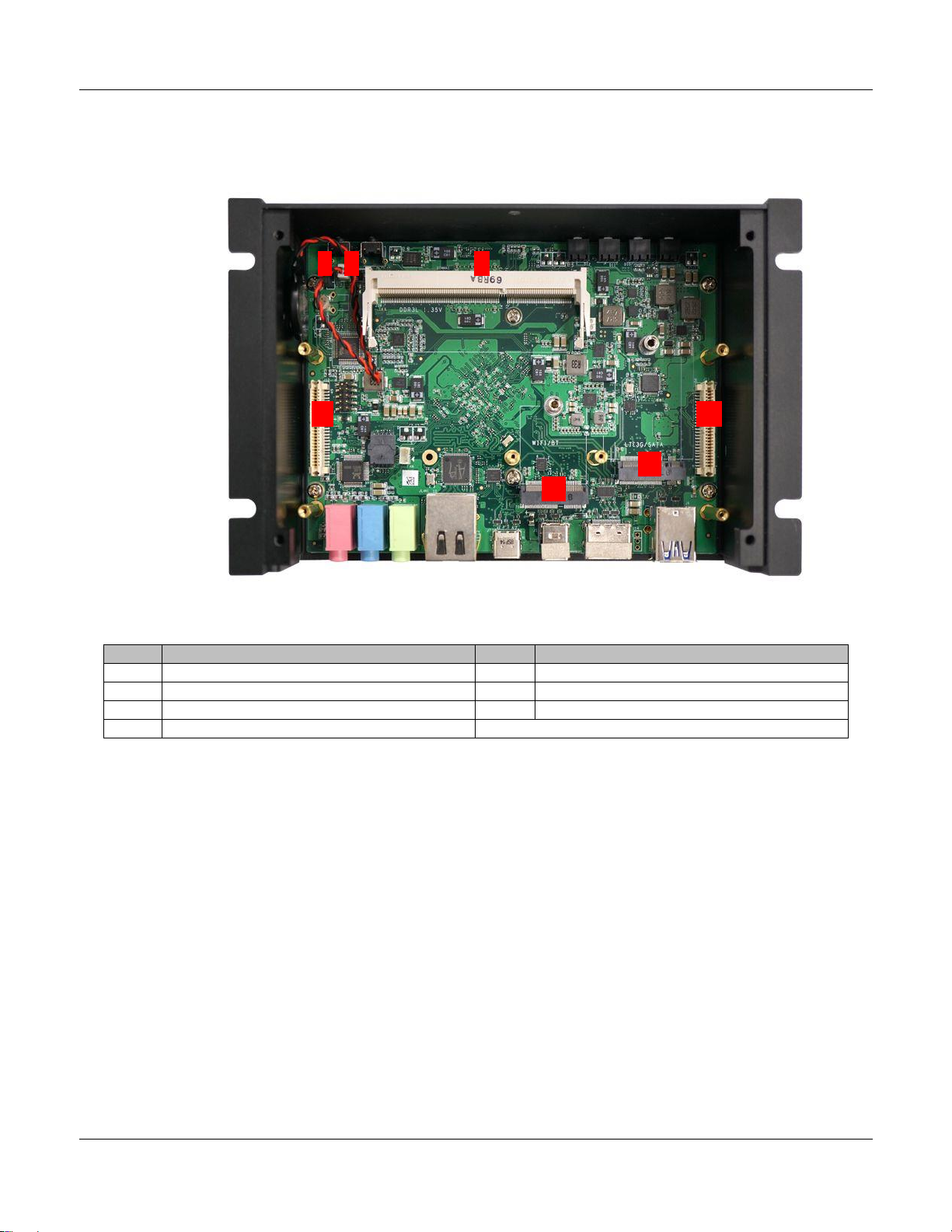
2.4.3. Board View Without the Power, I/O Expansion and SO-DIMM Modules
Rear view (opened device) without the I/O Expansion and Power Expansion modules:
A B C
F* G*
E*
D*
Internal Connectors and Switches:
No.
Description
No.
Description
A
CMOS jumper
E*
M.2 KEY-B slot (SATA + USB 2.0)
B
RTC Battery connector
F*
I/O Expansion module connector
C
SO-DIMM DDR3L slot
G*
Power Expansion module connector
D*
M.2 KEY-E slot (PCIe + USB 2.0)
NOTE: Items marked with * are accessible only after removing the I/O Expansion and Power Expansion
modules.

TEK3-BSW HARDWARE MANUAL –VER 1.00 APR 15 2019
Page 12 of 37
3. External Connectors
3.1. USB Host Connectors
The TEK3-BSW has two USB 3.0 Host connectors (USB 2.0 and USB 3.0 signals) to connect to a USB
peripheral such as a keyboard, mouse, USB storage device or USB hub.
3.2. HDMI (High Definition Multi-Media Interface) Connector
The HDMI interface available on the TEK3-BSW is based on Intel HD Graphics engine integrated into the
Intel Braswell processor and can be configured to support a secondary display.
The HDMI supports the following standards & features:
•High-Definition Multimedia Interface Specification, Version 1.4b
•Digital Visual Interface, Revision 1.0
•HDMI Compliance Test Specification, Version 1.4b
•Support for up to 720p at 100Hz and 720i at 200Hz or 1080p at 60Hz and 1080i/720i at 120Hz
HDTV display resolutions and up to QXGA graphic display resolutions.
•Support for 4k x 2k and 3D video formats
•Support for up to 16-bit Deep Color modes
3.3. miniDP (Mini DisplayPort) Connector
The miniDP interface available on the TEK3-BSW is based on Intel HD Graphics engine integrated into
the Intel Braswell processor and can be configured to support a secondary display.
The miniDP supports the following standards & features:
•DisplayPort 1.1a
•DisplayPort Content Protection
•High-bandwidth Digital Content Protection
•Refresh rate up to 240 FPS for 1080p at 24 bpp
•Support for up to 4k x 2k and 3D video formats
•Support for up to 48 bpp Color Depth
TEK3-BSW HARDWARE MANUAL –VER 1.00 APR 15 2019
Page 13 of 37
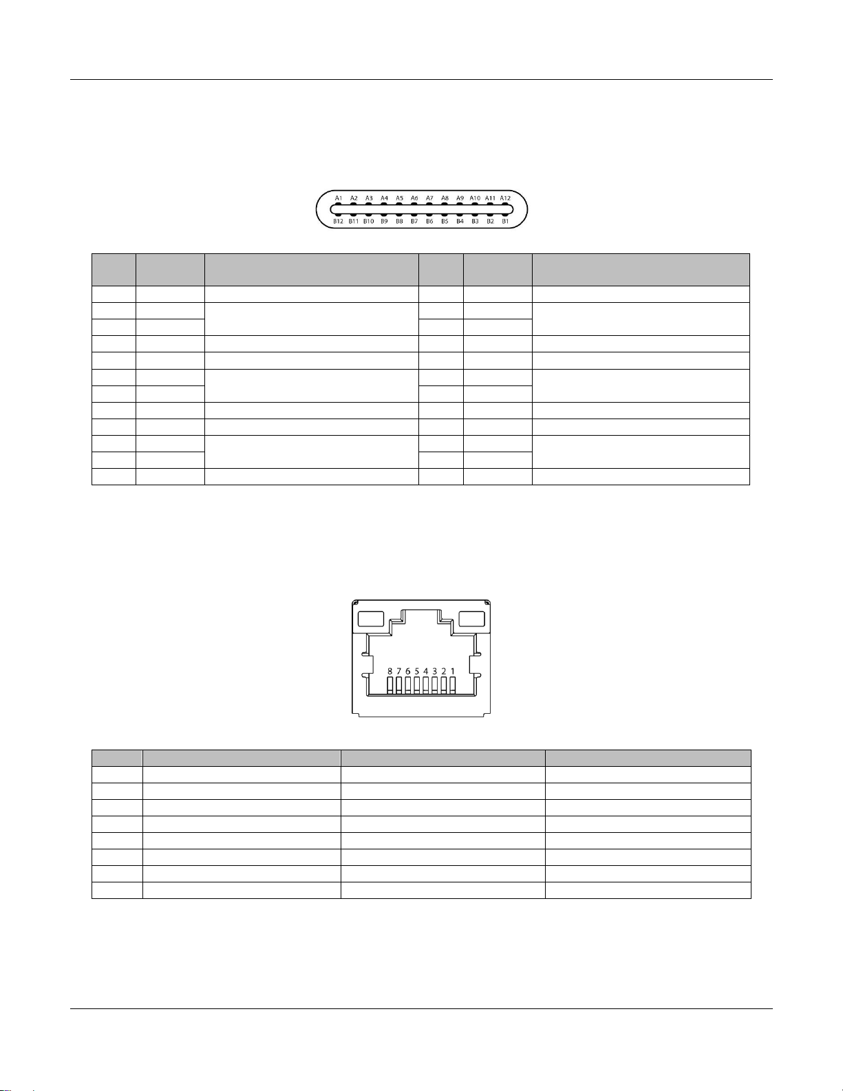
3.4. USB OTG (Type-C) Connector
The TEK3-BSW has one USB OTG Type-C connector (USB 2.0 and USB 3.0 signals) that can be used to
connect a host computer to the unit for programming and update purposes.
Pin
#
Signal
Description
Pin
#
Signal
Description
A1
GND
Ground
B1
GND
Ground
A2
TX1+
SS differential pair #1 signal
B2
TX2+
SS differential pair #3 signal
A3
TX1-
B3
TX2-
A4
VBUS
5V Universal Serial Bus Power
B4
VBUS
5V Universal Serial Bus Power
A5
CC1
OTG detection signal port 1
B5
CC2
OTG detection signal port 2
A6
USB_D+
USB differential pair signal
port 1
B6
USB_D+
USB differential pair signal
port 2
A7
USB_D-
B7
USB_D-
A8
SBU1
Sideband use port 1
B8
SBU1
Sideband use port 2
A9
VBUS
5V Universal Serial Bus Power
B9
VBUS
5V Universal Serial Bus Power
A10
RX2-
SS differential pair #4 signal
B10
RX1-
SS differential pair #2 signal
A11
RX2+
B11
RX1+
A12
GND
Ground
B12
GND
Ground
3.5. Gigabit Ethernet Interface (LAN1/LAN2)
The TEK3-BSW comes with two Gigabit Ethernet RJ45 connectors. LAN1 connector can support 802.3at
Power over Ethernet functionality if configured with the PoE power option (TEK3-xxxxx-Rxx-LPOE-xxx-
xxxx-xxxx-xxxx-xxxx) by connecting it to an 802.3at compliant PoE switch or power injector.
LAN1 / LAN2:
Pin #
1000 Mbps
100 Mbps
10 Mbps
1
MDI0+
Transmit Data+
Transmit Data+
2
MDI0-
Transmit Data-
Transmit Data-
3
MDI1+
Receive Data+
Receive Data+
4
MDI2+
5
MDI2-
6
MDI1-
Receive Data-
Receive Data-
7
MDI3+
8
MDI3-

TEK3-BSW HARDWARE MANUAL –VER 1.00 APR 15 2019
Page 14 of 37
3.6. Audio Connectors
The TEK3-BSW has three external 3.5mm stereo audio jacks.
Color Code
Signal
Description
Green
L/R Line out
Audio output
Blue
L/R Line in
Audio input
Pink
Mic in
Microphone input
3.7. Power Input Connector
The TEK3-BSW can be powered either over the DC INPUT connector or PoE (optional) over the RJ45
LAN1 port.
NOTE: Do not power the unit by DC input when you apply power over the Power over Ethernet (RJ45)!
Pin #
Signal
Description
1
GND
Ground
2
VCC
DC Voltage input (12V/24V/8~36VDC)
Header on TEK3-BSW: Molex 43045-0200 (2-pin Micro-Fit 3.0).
Cable receptacle: Molex 43025-0200 (2-pin Micro-Fit 3.0) plug with crimp contact Molex 43030-0007.
3.8. PWR Button
The TEK3-BSW features a “PWR” button for system power on. System is turned on when button is
pressed, and the Power LED Light indicator lit. If the system hangs, depressing the button for 5 seconds
powers down the system.
3.9. RST Button
The TEK3-BSW features a “RST” button for system reset.
3.10. Micro-SIM Connector
The TEK3-BSW features an external Micro-SIM cardslot for use by 3G/4G/LTE wireless module.
NOTE: This cardslot can be only used by a M.2 KEY-B 3G/4G/LTE module installed into the 3G/LTE
connector. The 3G/LTE connector can be found at location “E” in chapter 4. Internal Connectors and
Expansion Options of this manual. No M.2 KEY-B 3G/LTE module is included in this device (must be
purchased separately, not sold by TechNexion).

TEK3-BSW HARDWARE MANUAL –VER 1.00 APR 15 2019
Page 15 of 37
3.11. MicroSD Connector
The TEK3-BSW features a standard microSD cardslot which is connected to the Intel processor (Atom
x5-E8000 / Pentium N3710) integrated “Ultra Secured Digital Host Controller” (uSDHC).
The following main features are supported by uSDHC:
•Compatible with the MMC System Specification version 4.2/4.3/4.4/4.41/5.0.
•Conforms to the SD Host Controller Standard Specification version 3.0.
•Compatible with the SD Memory Card Specification version 3.0 and supports the “Extended
Capacity SD Memory Card”.
•Compatible with the SDIO Card Specification version 3.0.
•Supports 1-bit / 4-bit SD and SDIO modes
The MMC/SD/SDIO host controller can support a single MMC / SD / SDIO card or device.
3.12. LED Light Indicators
The TEK3-BSW has four programmable LED Light indicators.
LED #
Color
PCB Location
Registered Address
1
Green
LED-D12
0xFED8C400_BIT1 (Memory)
2
Green
LED-D11
0x99_BIT7 (SIO)
3
Green
LED-D10
0x81_BIT0 (SIO)
4
Green
LED-D9
0xE1_BIT4 (SIO)
LED Light 4 indicator is set as Power LED during manufacturing. The Power LED Light indicator is lit,
when the system is powered on.
LED #
Color
Power on
Power off
4
Green
ON
OFF
3.13. Antenna Holes
There are four antenna holes available (on the rear side). They come fitted with breakaway metal tabs. In
order to utilize them, the tabs must be removed by carefully using pincers or pliers.
TEK3-BSW HARDWARE MANUAL –VER 1.00 APR 15 2019
Page 16 of 37
3.14. Galvanic Isolated Connectors (TEK3-xxxxx-Rxx-Lxxx-xxx-xxxx-XG21-xxxx-
xxxx) (optional)
This product is available with three optional connectors: GPIO1, GPIO2, and RS-XXX that can be ordered
in either galvanic isolated or non-galvanic isolated versions. The TEK3-xxxxx-Rxx-Lxxx-xxx-xxxx-XG21-
xxxx-xxxx has three optional galvanic isolated connectors: GPIO1, GPIO2, and RS-XXX.
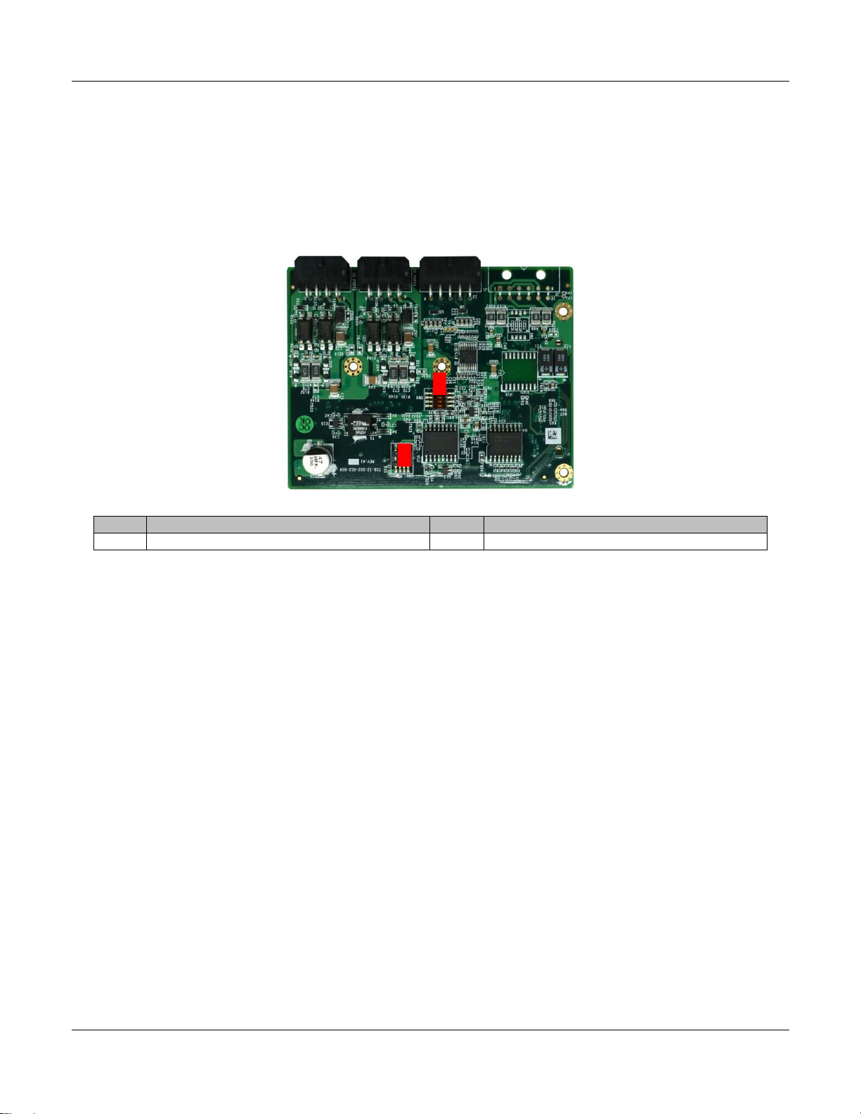
Top view of the galvanic isolated I/0 Expansion module (TXB-I2-GS2-GG8):
B
A
No.
Description
No.
Description
A
SW1 DIP switch
B
SW3 Terminator Resistor DIP switch

TEK3-BSW HARDWARE MANUAL –VER 1.00 APR 15 2019
Page 17 of 37
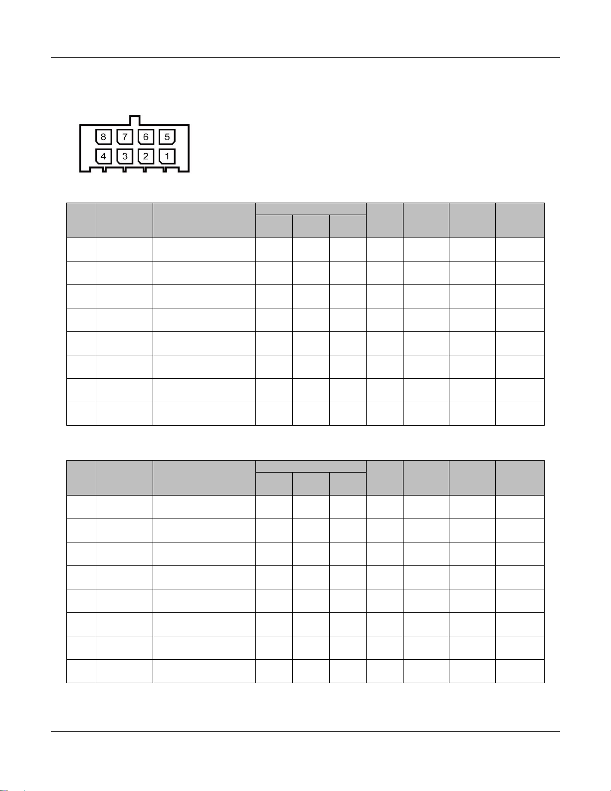
3.14.1. Galvanic Isolated Digital I/O Connectors (GPIO1/GPIO2) (optional)
The galvanic isolated GPIO Expansion headers have the following pinout:
GPIO1:
Pin
#
Signal
Description
Voltage
Curr
ent
Max.
Interfa
ce
Source
Control
ler
SIO
Pin #
Min.
Typ.
Max.
1
GPIO1A
DIG_IN1
4.75V
5V
5.25V
300
mA
LPC
Fintek
F81804
GPIO12
2
GPIO1B
DIG_IN2
4.75V
5V
5.25V
300
mA
LPC
Fintek
F81804
GPIO17
3
GND_DIO
Ground for digital
I/O
4
GND
Common Ground
5
GPIO1C
DIG_OUT5
11.21
V
11.8V
12.39
V
125
mA
LPC
Fintek
F81804
GPIO91
6
GPIO1D
DIG_OUT6
11.21
V
11.8V
12.39
V
125
mA
LPC
Fintek
F81804
GPIO94
7
VCC_DIO
Supply input for
digital I/O
5V
12.39
V
300
mA
8
VCC
Supply output
11.4V
12V
12.6V
300
mA
GPIO2:
Pin
#
Signal
Description
Voltage
Curr
ent
Max.
Interfa
ce
Source
Control
ler
SIO
Pin #
Min.
Typ.
Max.
1
GPIO2A
DIG_IN1
4.75V
5V
5.25V
300
mA
LPC
Fintek
F81804
GPIO93
2
GPIO2B
DIG_IN2
4.75V
5V
5.25V
300
mA
LPC
Fintek
F81804
GPIO16
3
GND_DIO
Ground for digital
I/O
4
GND
Common Ground
5
GPIO2C
DIG_OUT5
11.21
V
11.8V
12.39
V
125
mA
LPC
Fintek
F81804
GPIO92
6
GPIO2D
DIG_OUT6
11.21
V
11.8V
12.39
V
125
mA
LPC
Fintek
F81804
GPIO15
7
VCC_DIO
Supply input for
digital I/O
5V
12.39
V
300
mA
8
VCC
Supply output
11.4V
12V
12.6V
300
mA
Header on TEK3-BSW: Molex 43045-0800 (8-pin Micro-Fit 3.0).
Cable receptacle: Molex 43025-0800 (8-pin Micro-Fit 3.0) plug with crimp contact Molex 43030-0007.

TEK3-BSW HARDWARE MANUAL –VER 1.00 APR 15 2019
Page 18 of 37
3.14.2. Galvanic Isolated Serial Port (RS-XXX) (optional)
The dual 4-wire galvanic isolated serial port can be configured as follows: the primary serial port can only
be used as a standard RS-232. The secondary port can be configured either as RS-232, or RS-422 or
RS-485. This serial port is set by default as RS-232. Setting the TEK3-BSW in other mode will require to
open the device and adjust the internal SW1 DIP and SW3 Terminator Resistor DIP switch settings on
the TEP I/O Expansion board. The SW1 DIP switch can be found at location “A” and SW3 DIP switch at
location “B” in chapter 3.14. Galvanic Isolated Connectors (TEK3-xxxxx-Rxx-Lxxx-xxx-xxxx-XG21-xxxx-
xxxx) (optional) of this manual.
SW1:
Pin #
RS-232 (default)
RS-422
RS-485
1-8
ON
OFF
OFF
2-7
OFF
ON
OFF
3-6
OFF
OFF
ON
4-5
-
-
-
SW3:
Pin #
ON
OFF
1-8
Enable RS-485 Terminator Resistor
Disable RS-485 Terminator Resistor
2-7
Enable RS-422 Terminator Resistor
Disable RS-422 Terminator Resistor
3-6
-
-
4-5
-
-
RS-232 + RS-232 (default setup):
Pin #
Signal
Description
Device
1
GND
Ground
2
SERIAL1A_TXD
Port#1A Transmit data (output)
COM1
3
SERIAL1A_RXD
Port#1A Receive data (input)
COM1
4
SERIAL1A_RTS
Port#1A Request-to-send (output)
COM1
5
SERIAL1A_CTS
Port#1A Clear-to-send (input)
COM1
6
GND
Ground
7
SERIAL1B_TXD
Port#1B Transmit data (output)
COM2
8
SERIAL1B_RXD
Port#1B Receive data (input)
COM2
9
SERIAL1B_RTS
Port#1B Request-to-send (output)
COM2
10
SERIAL1B_CTS
Port#1B Clear-to-send (input)
COM2
TEK3-BSW HARDWARE MANUAL –VER 1.00 APR 15 2019
Page 19 of 37
RS-232 + RS-422:
Pin #
Signal
Description
Device
1~5
SERIAL1A
Identical as above
COM1
6
GND
Ground
7
SERIAL1B_TXD+
RS-422 Transmit positive data signal (output)
COM2
8
SERIAL1B_RXD-
RS-422 Receive negative data signal (input)
COM2
9
SERIAL1B_RXD+
RS-422 Receive positive data signal (input)
COM2
10
SERIAL1B_TXD-
RS-422 Transmit negative data signal (output)
COM2
RS-232 + RS-485:
Pin #
Signal
Description
Device
1~5
SERIAL1A
Identical as above
COM1
6
GND
Ground
7
SERIAL1B+
RS-485 positive data signal
COM2
8
NC
9
NC
10
SERIAL1B-
RS-485 negative data signal
COM2
Header on TEK3-BSW: Molex 43045-1000 (10-pin Micro-Fit 3.0).
Cable receptacle: Molex 43025-1000 (10-pin Micro-Fit 3.0) plug with crimp contact Molex 43030-0007.
3.15. Non-Galvanic Isolated Connectors (TEK3-xxxxx-Rxx-Lxxx-xxx-xxxx-XS21-
xxxx-xxxx) (optional)
This product is available with three optional connectors: GPIO1, GPIO2, and RS-XXX that can be ordered
in either galvanic isolated or non-galvanic isolated versions. The TEK3-xxxxx-Rxx-Lxxx-xxx-xxxx-XS21-
xxxx-xxxx has three optional non-galvanic isolated connectors: GPIO1, GPIO2, and RS-XXX.
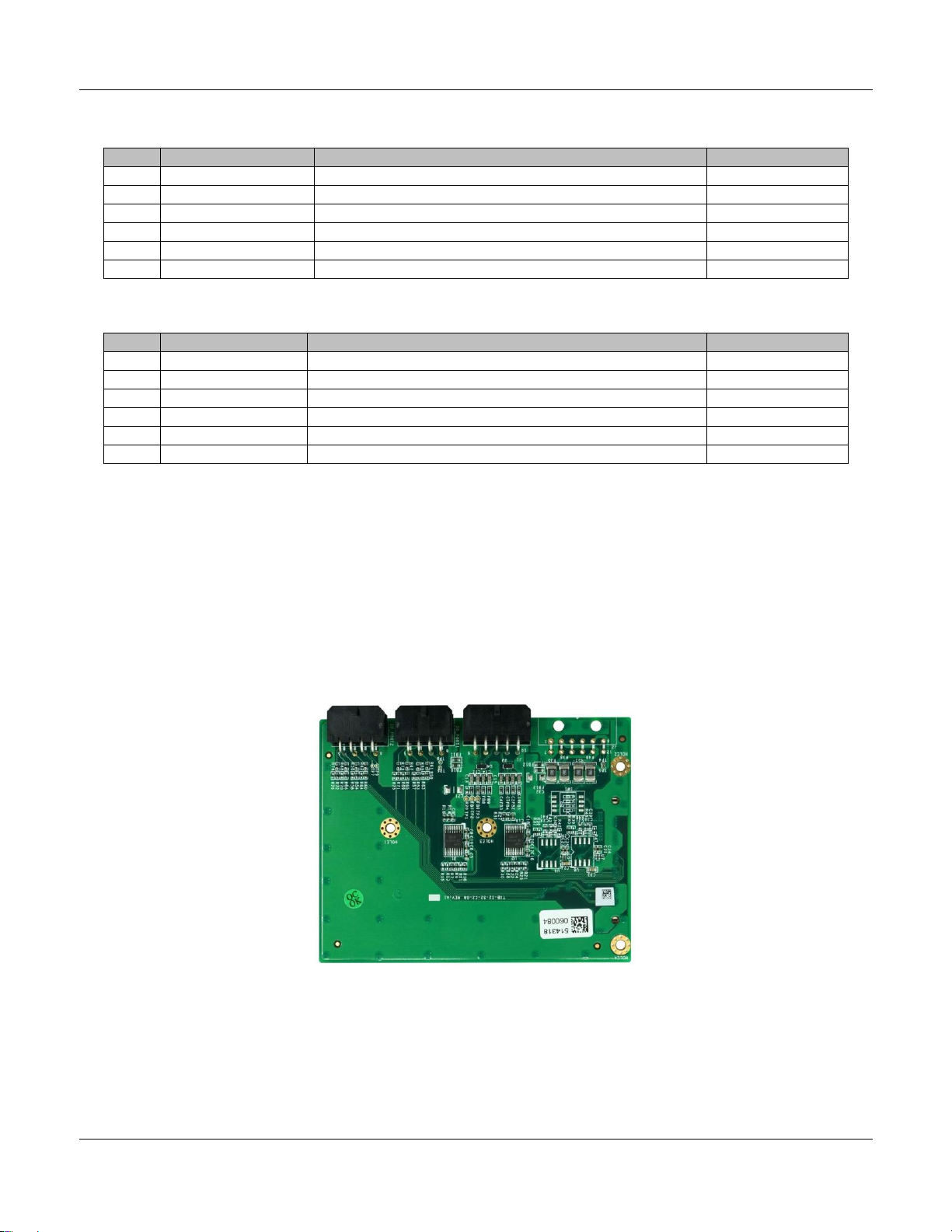
Top view of the non-galvanic isolated I/0 Expansion module (TXB-I2-S2-G8):
TEK3-BSW HARDWARE MANUAL –VER 1.00 APR 15 2019
Page 20 of 37
3.15.1. Non-Galvanic Isolated Digital I/O Connectors (GPIO1/GPIO2) (optional)
The non-galvanic isolated GPIO Expansion headers have the following pinout:
GPIO1:
Pin
#
Signal
Description
Voltage
Curr
ent
Max.
Interfa
ce
Source
Control
ler
SIO
Pin #
Min.
Typ.
Max.
1
GPIO1A
DIG_IN1/OUT1
3.14V
3.3V
3.46V
12
mA
LPC
Fintek
F81804
GPIO12
2
GPIO1B
DIG_IN2/OUT2
3.14V
3.3V
3.46V
12
mA
LPC
Fintek
F81804
GPIO17
3
NC
4
GND
Common Ground
5
GPIO1C
DIG_IN5/OUT5
3.14V
3.3V
3.46V
12
mA
LPC
Fintek
F81804
GPIO91
6
GPIO1D
DIG_IN6/OUT6
3.14V
3.3V
3.46V
12
mA
LPC
Fintek
F81804
GPIO94
7
NC
8
VCC
Supply output
11.4V
12V
12.6V
300
mA
GPIO2:
Pin
#
Signal
Description
Voltage
Curr
ent
Max.
Interfa
ce
Source
Control
ler
SIO
Pin #
Min.
Typ.
Max.
1
GPIO2A
DIG_IN1/OUT1
3.14V
3.3V
3.6V
12
mA
LPC
Fintek
F81804
GPIO93
2
GPIO2B
DIG_IN2/OUT2
3.14V
3.3V
3.6V
12
mA
LPC
Fintek
F81804
GPIO16
3
NC
4
GND
Common Ground
5
GPIO2C
DIG_IN5/OUT5
3.14V
3.3V
3.6V
12
mA
LPC
Fintek
F81804
GPIO92
6
GPIO2D
DIG_IN6/OUT6
3.14V
3.3V
3.6V
12
mA
LPC
Fintek
F81804
GPIO15
7
NC
8
VCC
Supply output
11.4V
12V
12.6V
300
mA
Header on TEK3-BSW: Molex 43045-0800 (8-pin Micro-Fit 3.0).
Cable receptacle: Molex 43025-0800 (8-pin Micro-Fit 3.0) plug with crimp contact Molex 43030-0007.
Other manuals for TEK3-BSW
1
Table of contents
Other TechNexion Desktop manuals

TechNexion
TechNexion AXON-WIZARD-IMX8M-MINI User manual

TechNexion
TechNexion TEK3-BSW User manual

TechNexion
TechNexion SBC-APL-350 User manual

TechNexion
TechNexion TEK3-IMX6UL User manual

TechNexion
TechNexion TEK3-IMX6UL User manual

TechNexion
TechNexion TEK5-APL User manual

TechNexion
TechNexion TCK3-APL User manual
Popular Desktop manuals by other brands

IEI Technology
IEI Technology ECW-281B-BTi user manual

Dell
Dell Precision 3430 Small Form Factor installation guide

Compaq
Compaq Professional Workstation AP200 Maintenance and service guide

HP
HP EliteDesk 705 G5 Maintenance and service guide

Lenovo
Lenovo ThinkCentre Edge 71z null

Lenovo
Lenovo IdeaCentre A540 Series Setup guide


