TechNexion TEK5-APL User manual

4External Connectors
TEK5-APL
Quickstart Guide
3 Installaon Instrucons
This secon describes the mounng procedures for TEK series device. The material in the mounng area must provide sufficient strength for support of this embedded
box PC.
3.1 Surface Mounng
There are 4 mounng holes (M5) on the top side of the device required for surface mounng. Four M4 or M5 screws with at least 8mm head-to-p length are required
to secure this device to the surface.
INNOVATORS OF TECHNOLOGY
2Dimensions
1 Safety Precauons
Thank you for purchasing a TechNexion TEK series device. This installaon guide will be helpful in the installaon, wiring and inspecon of your TechNexion embedded
fanless box PC. Before using the product, please read this guide to ensure correct use. You should thoroughly understand all safety precauons before proceeding with
the installaon, wiring, and operaon. Place this instrucon sheet in a safe locaon for future reference. The following suggesons will help you.
• Keep the device dry. Precipitaon, humidity, and all types of liquids or moisture can contain minerals that will corrode electronic circuits. If your device does get wet,
allow it to dry completely.
• Do not use or store the device in dusty or dirty areas. Its parts and electronic components can be damaged.
• Do not store the device in hot areas. High temperatures can shorten the life of electronic devices, damage baeries, and warp or melt certain plascs.
• Do not store the device in cold areas. When the device returns to its normal temperature, moisture can form inside the device and damage electronic circuit boards.
• Do not aempt to open the device. This product is designed for specific applicaons and needs to be installed by qualified personnel.
• Do not drop, knock, or shake the device. Rough handling can break internal circuit boards and fine mechanics.
• Do not paint the device. Paint can clog the parts and prevent proper operaon.
• Unauthorized modificaons or aachments could damage the device and may violate regulaons governing radio devices.
• Do not touch any internal or exposed parts of the device as electrical shock may result.
• Do not open the device while power is on. Otherwise electrical shock may result.
• Do not use harsh chemicals, cleaning solvents, or strong detergents to clean the device.
• Be sure the venlaon holes are not obstructed during operaon. Otherwise malfuncon may result due to bad venlaon or overheang.
These suggesons apply equally to your device, baery, charger, or any enhancement. If any device is not working properly, take it to the nearest authorized service
facility for service.
•Make sure that the available power source matches the required input power of the device. Failure to observe this cauon may result in electric shock or fire.
•Do not power the unit by DC input when you apply power over the PoE (RJ45).
1.1 Storage and Installaon
1.2 Wiring
1.3 Maintenance and Inspecon
!
Unit : mm
Description No.No. Description
1
2A
2B
3
4
5A
5B
6
7
8
9
10
11A
11B
12
13
14
15
16
17
18
19A
19B
19C
19D
20
21
22
23
24A
24B
24C
25
Power Input connector
SIM1 (Mini-SIM) card slot
SIM2 (Mini-SIM) card slot
microSD card slot
2x USB 3.0 Host connector
2x USB 2.0 Host connector
2x USB 2.0 Host connector
LED Light 1/2/3/4 indicators
Power LED indicator
SATA LED indicator
Power button
Reset button
Antenna hole
Antenna hole
Grounding screw
LAN1 RJ45 connector
LAN2 RJ45 connector
OPT-A connector hole
OPT-B connector hole
2.5” SSD Drive Rack
GPIO DB15 connector
RS-XXX1 (Serial Port) DB9 connector
RS-XXX2 (Serial Port) DB9 connector
RS-XXX3 (Serial Port) DB9 connector
RS-XXX4 (Serial Port) DB9 connector
DVI-D connector
DP connector
3.5mm jack Mic in
3.5mm jack Line out
Antenna hole
Antenna hole
Antenna hole
VGA (15-pin D-SUB) connector
4 6 7 8 9
Front view:
1 2A 2B 105A3
11A 11B 24A 19D 19B 24B 24C
12 5B 1513 16 17 2514
Rear view:
18 19C 19A 2120 22 23
1 2
286
145
110
250
145
60
170
180
4.2
270
67.7
65.5
• All Rights Reserved. No part of this document may be photocopied, reproduced, stored in a retrieval system, or transmied, in any form or by any means whether, electronic, mechanical, or otherwise
without the prior wrien permission of TechNexion Ltd.
• No warranty of accuracy is given concerning the contents of the informaon contained in this publicaon. To the extent permied by law no liability (including liability to any person by reason of
negligence) will be accepted by TechNexion Ltd., its subsidiaries or employees for any direct or indirect loss or damage caused by omissions from or inaccuracies in this document.
• TechNexion Ltd. reserves the right to change details in this publicaon without noce. Please download the most updated version at: hps://www.technexion.com/support/download-center/
Phone: +886-2-82273585 Web: www.technexion.com
16F-5, No. 736, Zhongzheng Road, ZhongHe District, 23511, New Taipei City, Taiwan
© 2001-2019 TechNexion Ltd.
2019-12-03
5.1.1 Digital I/O Connector (GPIO)
5.1.2 Serial Ports (RS-XXX1/RS-XXX2/RS-XXX3/RS-XXX4)
5.2.1 Digital I/O Connector (GPIO)
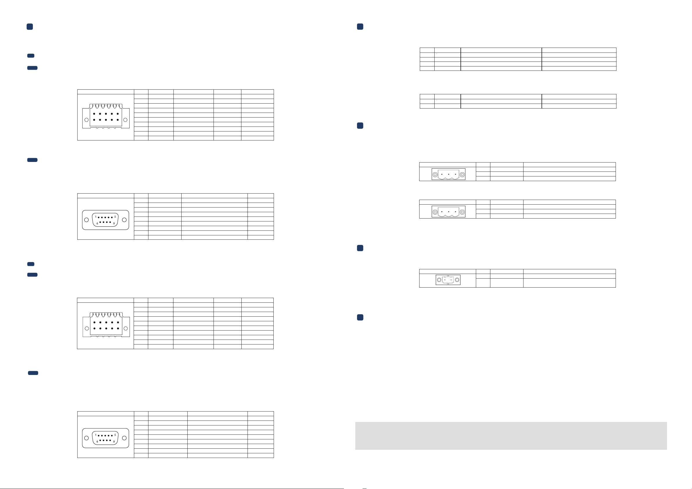
5.1 Galvanic Isolated Connectors Pin Definion (TEK5-Exxxx-Rxx-x-I-xxx-xxxx-xxxxx-x-xxxx-TI-xxxx) (oponal)
5.2 Non-Galvanic Isolated Connectors Pin Definion (TEK5-Exxxx-Rxx-x-N-xxx-xxxx-xxxxx-x-xxxx-TI-xxxx) (oponal)
5 Pin Definion 6LED Light Indicators
7 Power Input Connector
8 Remote Power Buon Connector
This product is available with one GPIO connector. The galvanic isolated GPIO connector has the following pinout:
This product is available with five connectors: GPIO, RS-XXX1, RS-XXX2, RS-XXX3, and RS-XXX4 that can be ordered in either a
galvanic isolated or non-galvanic isolated version.
This product is available with four full funcon galvanic isolated serial ports.
RS-XXX1/RS-XXX2 are set as RS-232 during manufacturing. For seng details of RS-XXX1/RS-XXX2 serial ports in other modes,
please refer to the TEK5-APL HARDWARE MANUAL. RS-XXX3/RS-XXX4 serial ports can be used as a standard RS-232 only. The
ports have the following pinout:
The TEP5-APL can be powered over the DC INPUT connector. This device can be ordered with (TEK5-Exxxx-Rxx-P-x-xxx
-xxxx-xxxxx-x-xxxx-TI-xxxx) or without (TEK5-Exxxx-Rxx-L-x-xxx-xxxx-xxxxx-x-xxxx-TI-xxxx) a power ignion feature.
Header on TEP5-APL: DINKLE 2EHDRM-03P (3-pin 5.08mm pitch terminal block with threaded flange).
Cable receptacle: DINKLE 2ESDVM-03P (3-pin 5.08mm pitch terminal block connector plug).
Header on TEP5-APL: DINKLE 0225-1602 (2-pin 3.50mm pitch terminal block with threaded flange).
Cable receptacle: DINKLE 0225-0602 (2-pin 3.50mm pitch terminal block connector plug).
TEK5-Exxxx-Rxx-P-x-xxx-xxxx-xxxxx-x-xxxx-TI-xxxx:
TEK5-Exxxx-Rxx-L-x-xxx-xxxx-xxxxx-x-xxxx-TI-xxxx:
This product is available with one GPIO connector. The non-galvanic isolated GPIO connector has the following pinout:
The TEK5-APL has six LED light indicators including four programmable LED Light indicators.
The TEP5-APL features a remote power buon connector.
Header on TEP5-APL: DINKLE 0156-1810L (10-pin 2.54mm pitch terminal block) connector socket.
Cable receptacle: DINKLE 0156-1A10-BK (10-pin 2.54mm pitch terminal block) connector plug.
LED# Color
PCB Location
Registered Address
1 LED-A1
LED-A2
LED-A3
LED-A4
Green
Green
Green
Green
0xF9_BIT4 (SIO)
0xF9_BIT3 (SIO)
0xED_BIT2 (SIO)
0xED_BIT1 (SIO)
2
3
4
LED# Color
ON
OFF
5 Power on
SATA SSD is active (blinking)
Green
Red
Power off
SATA SSD is not active
6
GPIO:
RS-XXX1/RS-XXX2/
RS-XXX3/RS-XXX4:
GPIO:
Port Pin #
Signal
1
2
3
4
5
6
7
8
9
10
GPIO1A
GPIO1B
GPIO1C
GPIO1D
GPIO1E
GPIO1F
GPIO1G
GPIO1H
GND
VCC
Description Voltage
Voltage
DIG_IN1
DIG_OUT1
DIG_IN2
DIG_OUT2
DIG_IN3
DIG_OUT3
DIG_IN4
DIG_OUT4
Common Ground
Supply output
5V
12V
5V
12V
5V
12V
5V
12V
5V
Current Max.
1A
125 mA
1A
125 mA
1A
125 mA
1A
125 mA
300 mA
Header on TEK5-APL: DB9 (9-pin) standard D-Sub male connector.
Cable receptacle: DB9 (9-pin) standard D-Sub female connector.
Header on TEP5-APL: DINKLE 0156-1810L (10-pin 2.54mm pitch terminal block) connector socket.
Cable receptacle: DINKLE 0156-1A10-BK (10-pin 2.54mm pitch terminal block) connector plug.
Port Pin #
Signal
1
2
3
4
5
7
6
8
9
SERIAL1/2/3/4_DCD
SERIAL1/2/3/4_RXD
SERIAL1/2/3/4_TXD
SERIAL1/2/3/4_DTR
GND
SERIAL1/2/3/4_DSR
SERIAL1/2/3/4_RTS
SERIAL1/2/3/4_CTS
VCC*
Description Device
Data Carrier Detect (input)
Receive data (input)
Transmit data (output)
Data Terminal Ready (output)
Ground
Data Set Ready (input)
Request-to-send (output)
Clear-to-send (input)
5V supply output (current max. 500mA)
COM1/2/3/4
COM1/2/3/4
COM1/2/3/4
COM1/2/3/4
COM1/2/3/4
COM1/2/3/4
COM1/2/3/4
The unit is by default preloaded with soware that can download and install a selecon of Linux OS images over hardwired network. Simply connect a display to the
unit though the DP or DVI-D or VGA connector and a network through the Ethernet LAN RJ45 connector and power it up, then follow the steps on the screen to load
the soware. Local proxies will interfere with this process. For more informaon, go to our Knowledge Base at: hps://www.technexion.com/support/knowledge-base/
To download drivers for the Windows operang systems, go to our Download Center at:
hps://www.technexion.com/support/download-center/
For more informaon about installing and configuring the Windows operang systems, see: hps://msdn.microso.com/en-us/
9 Soware and Driver Installaon
3 4
1
6 9
5
Besides, the TEP5-APL features Power LED and SATA LED indicators. The Power LED Light indicator is lit,
when the system is powered on. The SATA LED Light indicator is blinking, when the SATA SSD is acve.
5.2.2 Serial Ports (RS-XXX1/RS-XXX2/RS-XXX3/RS-XXX4)
RS-XXX1/RS-XXX2 are set as RS-232 during manufacturing. For seng details of RS-XXX1/RS-XXX2 serial ports in other modes,
please refer to the TEK5-APL HARDWARE MANUAL. RS-XXX3/RS-XXX4 serial ports can be used as a standard RS-232 only. The
ports have the following pinout:
This product is available with four full funcon non-galvanic isolated serial ports.
RS-XXX1/RS-XXX2/
RS-XXX3/RS-XXX4:
Header on TEK5-APL: DB9 (9-pin) standard D-Sub male connector.
Cable receptacle: DB9 (9-pin) standard D-Sub female connector.
Port Pin #
Signal
1
2
3
4
5
7
6
8
9
SERIAL1/2/3/4_DCD
SERIAL1/2/3/4_RXD
SERIAL1/2/3/4_TXD
SERIAL1/2/3/4_DTR
GND
SERIAL1/2/3/4_DSR
SERIAL1/2/3/4_RTS
SERIAL1/2/3/4_CTS
VCC*
Description Device
Data Carrier Detect (input)
Receive data (input)
Transmit data (output)
Data Terminal Ready (output)
Ground
Data Set Ready (input)
Request-to-send (output)
Clear-to-send (input)
5V supply output (current max. 500mA)
COM1/2/3/4
COM1/2/3/4
COM1/2/3/4
COM1/2/3/4
COM1/2/3/4
COM1/2/3/4
COM1/2/3/4
1
6 9
5
Port Pin #
Signal
1
2
3
4
5
7
6
8
9
10
GPIO1A
GPIO1B
GPIO1C
GPIO1D
GPIO1E
GPIO1F
GPIO1G
GPIO1H
GND
VCC
Description Current Max.
DIG_IN1
DIG_OUT2
DIG_IN3
DIG_OUT4
DIG_IN5
DIG_OUT6
DIG_IN7
DIG_OUT8
Common Ground
Supply output
3.3V
3.3V
3.3V
3.3V
3.3V
3.3V
3.3V
3.3V
5V
12 mA
12 mA
12 mA
12 mA
12 mA
12 mA
12 mA
12 mA
300 mA
1
2
3
4
5
6
7
8
9
10
1
2
3
4
5
6
7
8
9
10
Connector Pin #
Signal
1
2
3
VCC
GND
IGN
Description
DC Voltage input (8~36VDC)
Ground
Signal from MCU
1 32
Connector Pin #
Signal
1
2
3
VCC
GND
NC
Description
DC Voltage input (8~36VDC)
Ground
1 32
Connector Pin #
Signal
1
2
PWRON
GND
Description
Switch power source
Ground
1 2
Other manuals for TEK5-APL
1
Other TechNexion Desktop manuals

TechNexion
TechNexion TCK3-APL User manual

TechNexion
TechNexion TEK3-IMX6UL User manual

TechNexion
TechNexion SBC-APL-350 User manual

TechNexion
TechNexion TEK3-BSW User manual

TechNexion
TechNexion AXON-WIZARD-IMX8M-MINI User manual

TechNexion
TechNexion TEK3-BSW User manual

TechNexion
TechNexion TEK3-IMX6UL User manual


