Techni Mobili RTA-B005 User manual

SIT-TO-STAND ROLLING ADJUSTABLE
LAPTOP CART WITH STORAGE
MODEL RTA-B005
ASSEMBLY INSTRUCTIONS
REV.OL-6941-0922
Thank you for purchasing our product
Scan to view full
assembly video
•Please be kind to our planet, when done with the assembly,
recycle any of the packaging materials that is accepted by
your city or recycling service. Thank you!
P.1 P.1
RTA-B005
•Please read carefully the assembly instructions before the installation.
• Do not discard this manual or any of the packaging
material until the unit has been completely assembled.
•Scan this QR code to view the complete assembly video online.
•For individual Step videos - please use the QR code found on
the corresponding step within the manual. SAMPLE - DO NOT SCAN
P.2 P.2
RTA-B005
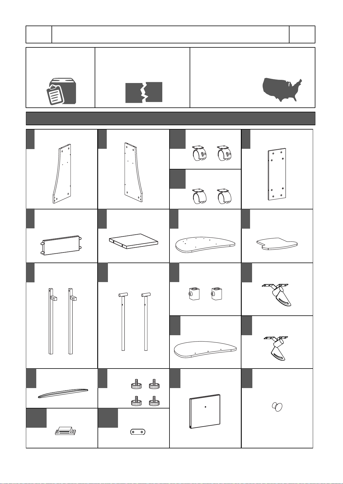
1
x1 2
x1 3-L
x2 4
x1
Left side panel
The replacement parts service is limited to
the 48 contiguous United States.
If you reside in AK, HI, PR, U.S. territories
or other countries,
please contact the
supplier from where
the unit was purchased.
Missing, damaged and defective
parts can be replaced at no cost
to you. Please refer to the last
pages on this manual.
Do a quick inventory
of all the parts and
hardware listed below
MAIN PARTS LIST
Right side panel Locking Casters Back panel
5
x1 6
x1 7
x1 8
x1
Front bottom panel Middle lower shelf Bottom base panel Middle upper shelf
9
x2 10
x2 11A
x2
12
x1
Lateral support bar Lifting "T" tube Tightening plastic
cover
Main top panel
13
x1
15
x1 16
x4
17-A
x1
Right tilting
mechanism
Protection rail Tightening screw
knob
Magnet
3-N
x2 Non-Locking
Casters
14
x1 Left tilting
mechanism
17-B
x1
Small steel
plate
18
x1 Shelf door 19
x1 Door handle

16
P.3 P.3
RTA-B005
PART QTY SIZE
MAIN PARTS LAYOUT (For reference)
HARDWARE LIST
16 M4x14
A
ITEM
3
B
6
C
20
D
8
E
PART QTY SIZE
4M3x15
F
ITEM
1
G
2
H
2
Sets
I
INCLUDED TOOLS
1Phillips Screwdriver
M5x16
M6x35
M6x40
Bolt
M6x12
M4x20
Ø5x17
Ø8x19 Curved
connector
__________
12
13
14
16
8
12
7
5
9
18
11
15
10
10
4
3-L
Ø10x28
Plastic washer
P.4 P.4
RTA-B005
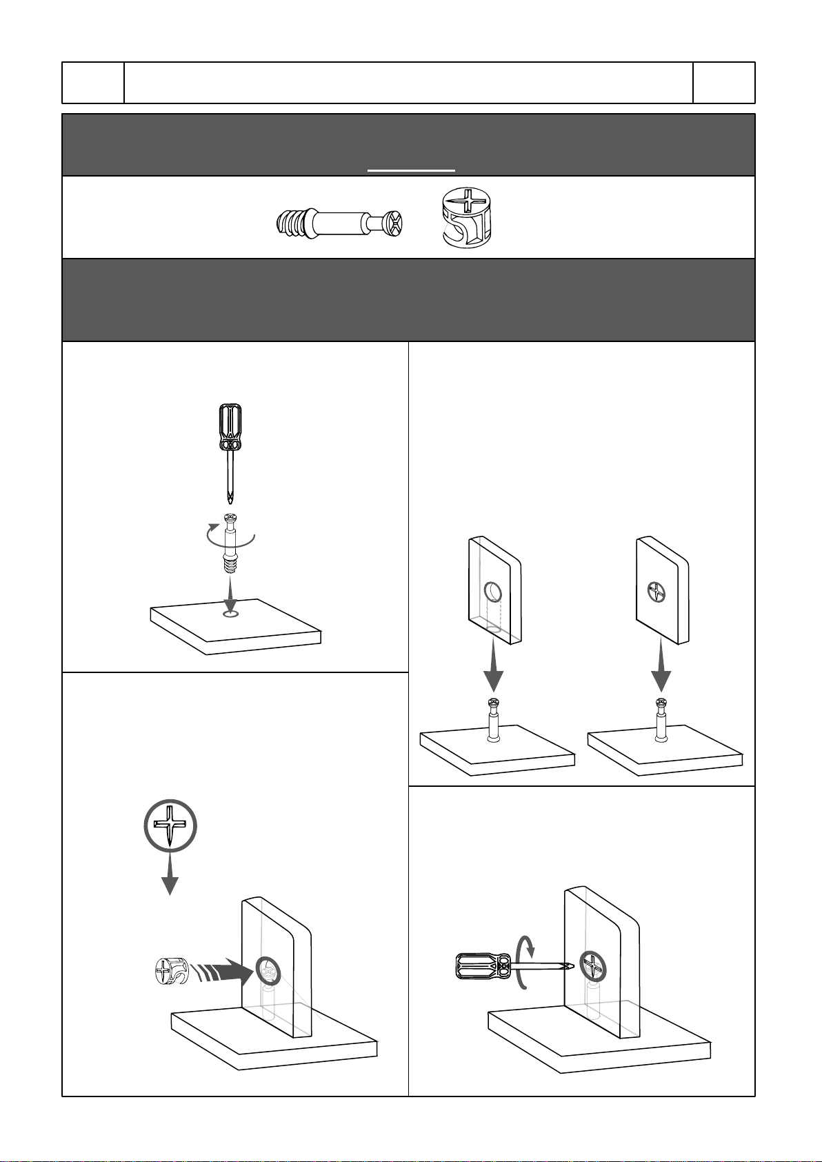
1. Screw the bolt into the indicated hole on the
panel indicated in the assembly step.
CAM BOLT AND CAM LOCK TUTORIAL
THE INSTRUCTIONS BELOW ARE NOT ACTUAL ASSEMBLY STEPS
This unit uses cam bolts and locks (also known as mini fixes).
If you are not familiar with this kind of hardware, the below is a tutorial
that explains how to use them on the steps where they are required.
2. Join the other panel (with the big hole) to the
panel with the bolt. If it comes with the cam
locks already pre-installed, make sure to align
them to receive the bolt's head (refer to point
3). There might be a very small gap between
the panels which is normal.
3. Insert the cam lock on the panel with the big
hole making sure it goes aligned to receive the
bolt's head.
4. Use a Phillips screwdriver to turn the cam
lock clockwise. This will lock the panels
togheter and also will close any gaps.
Cam lock
alignment
If the cam locks come
pre-in stalled, make sure they
are aligned (see point 3).
P.5 P.5
RTA-B005
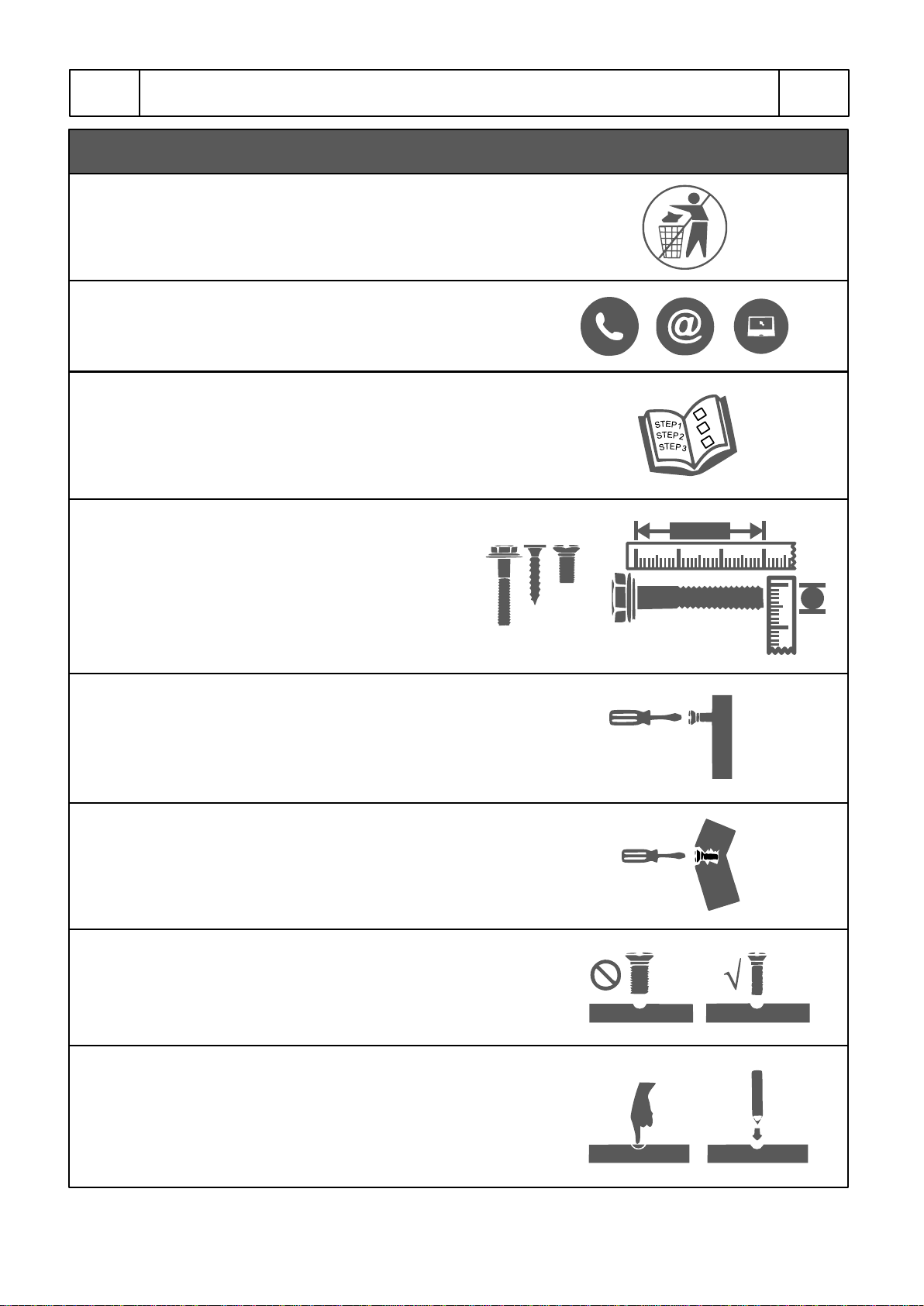
BEFORE YOU START THE ASSEMBLY, PLEASE READ THE FOLLOWING TIPS AND WARNINGS.
• If during assembly you find an issue or need clarification,
please contact our Customer Service for assistance.
Please refer to the last pages on this manual.
• On each step read the instructions thoroughly and
analyze the illustrations before proceeding to do the
assembly.
• Follow the instructions step by step and do not skip any
unless our Customer Service advises it is OK to do so.
• Do not overtighten or force the screws as they might
break, strip, damage the threads of the holes or get stuck
inside the part.
• Make sure you understand which hardware will be
used on each step. Using the wrong size of screw,
bolt or pin might strip the threads or cause damage
to the part in which it is being used.
• To avoid misalignments, always leave the screws loose
and tighten them until all pieces are positioned correctly.
• If the hole seems too small for the screw, make sure you
are using the correct size of screw and/or that you are
installing it in the correct hole.
• Do not discard this manual or any of the packaging
material until the unit has been completely assembled.
√
√
M6
30mm
M6x30
•Sometimes on the panels the laminate or material might be
covering the hole partially or entirely. If there is no visible
hole or it seems too small, pass and press the tip of your
finger over the area where the hole should be located to feel
its indentation, and once found, carefully pierce the laminate
to uncover the hole underneath.

P.6 P.6
RTA-B005
Attach the magnet 17-A to the bottom surface of the middle upper shelf 8with
screws F.
Attach the small steel plate 17-B to the inside surface of the shelf door 18 with
screws F.
STEP 1
Hardware
FM3x15 4
Pcs
17-A
ASSEMBLY STEPS
1
4
5
6
8
Tools (included)
Scan QR to view step
5
(Bottom face)
(Inside face)
Screw the bolts Dinto panel 1.
Join panel 4to panel 1and turn the cam locks as explained in page 4.
Assemble panel 6to panel 1in the same way making sure the surface with the
cam locks towards the BOTTOM.
Join panel 5to panel 1.
STEP 2
Hardware
DM6x40 4
Pcs
Tools (included)
Scan QR to view step Attach bolts to 1
(Front)
(Top)
(Front)
(Bottom)
(Top)
(Front)
Assemble 4 to 1
Cam locks
alignment
on 4 and 6
(Front)
Assemble 6 to 1
(Front)
Attach 5 to 1
17-B
18
11
1
(Bottom)
(Top)

Attach bolts to 2
(Top)
(Front)
P.7 P.7
RTA-B005
Insert the metal pin Hinto the corresponding hole on panel 1.
Attach the door panel 18 to the pin H, making sure the metal plate is visible as
shown.
STEP 3
Hardware
HDouble
sided pin
1
Pc
(Front)
(Bottom face)
3-N
H
Non-Locking
go at the back
46
7
18
Tools (included)
Scan QR to view step
1H
Attach the bolts Dto the right side panel 2into the indicated holes.
Insert the metal pin Hinto the door 18.
Assemble panel 2to panels 4, 5, 6 and 18 as shown and as explained in page 4.
STEP 4
Hardware
DM6x40
Bolt
4
Pcs
Tools (included)
Scan QR to view step
X2
X2
HDouble
sided pin
1
Pc
Insert H into 18
H
18
Attach 2 to 4, 5, 6
2
2
5
Cam locks
alignment
on 4 and 6 18
Use screws Ato assemble the casters 3to the bottom surface of the bottom
base panel 7in the following positions:
The Locking casters 3-L go at the front of the panel.
The Non-locking casters 3-N go at the back of the panel.
STEP 5
Hardware
AM4x14 16
Pcs
Tools (included)
Scan QR to view step
Locking
go at the front
3-L

Screw the bolts Dinto the indicated holes on the top surface of pa
nel 7.
Join the main frame to the base and lock the pieces together by turning the
cam locks on panels 1, 2 and 4 as shown and as explained in page 4.
STEP 6
Hardware
DM6x40 6
Pcs
Tools (included)
Scan QR to view step Attach bolts to 7
P.8 P.8
RTA-B005
(Front)
1
4
8
9
Cam locks
alignment
on 1, 2 & 4
7
2
Screw the bolts Dto the middle upper shelf 8.
Assemble the shelf 8to panels 1, 2and 4as explained in page 4.
STEP 7
Hardware
DM6x40 6
Pcs
Tools (included)
Scan QR to view step
Attach bolts to 8 8
1
4
2
Assemble the lateral support bars 9to the base panel 7with screws C from
underneath. The screws go through the base panel and into the bars.
Assemble the bars 9to the side panels 1and 2with screws Cfrom the side.
The screws go through the bars and into the side panels.
STEP 8
Hardware
CM6x35 6
Pcs
Tools (included)
Scan QR to view step
9
7
12
99
(Front)
(Front)
Cam locks
alignment
on 1, 2 & 4

Secure all pieces
by tightening the
screw knob 16
into the tube 10
P.9 P.9
RTA-B005
Place the curved connectors I over the threaded holes of the lifting tubes 10.
Place the washer I over the connector I.
Connect the right tiltilg mechanism 13 to the tube 10.
Insert and screw the screw knob 16 into the tube 10. The screw knob goes
through the mechanism 13, the washer I, the connector I and into the tube 10.
Repeat the procedure for the left tilting mechanism 14.
THE SOFT PLASTIC WASHER MUST GO IN BETWEEN THE CONNECTOR
AND THE MECHANISM, AS IT PURPOSE IS TO CREATE THE NECESSARY
FRICTION THAT KEEPS THE MECHANISM FIRM WITHOUT MOVING.
DO NOT PLACE THE WASHER OVER THE MECHANISM, IT MUST GO
UNDER IT.
IF THE SOFT PLASTIC WASHER IS MISSING, DO NOT REPLACE IT WITH
ANY OTHER KIND; DO NOT USE METAL OR HARD PLASTIC WASHERS.
STEP 9
Hardware
IConnector 2
Sets
I
10
14
Soft plastic
washer
Scan QR to view step
REPEAT THE
PROCEDURE FOR
MECHANISM 14
EXTREMELY IMPORTANT!
Follow this step EXACTLY as instructed! An incorrect assembly leaves
the tilting mechanism and main panel prone to moving or sliding, and
even might flip down forwards unexpectedly under any weight.
Place Connector I
over tube 10
I
10
Place Washer I
over connector I
The washer goes OVER
THE CONNECTOR, NOT
over the mechanism.
10
Connect mechanism
13 to tube 10
If the soft plastic washers are
missing, DO NOT replace them
with metal or hard plastic washers.
13
16
16
I: Connector
I: Washer
10
Hollow
end
Tilting direction
13

Do not
tighten
P.10 P.10
RTA-B005
Assemble the tilting mechanisms 13 and 14 to the main panel 12 in their
respective sides with screws E.
STEP 10
Hardware
EM6x12 8
Pcs
12
13 14
16
Tools (included)
Scan QR to view step
Holefacingto
theoutside
(Front)
(Left)
(Right)
Place the plastic covers 11 over the lateral bars 9with their threaded holes
facing towards the outside.
Slide the lifting tubes 10 through the plastic covers 11 and into the bars 9.
Insert the screw knobs 16 into the plastic covers 11, but do not tighten yet.
STEP 11
Scan QR to view step
11
9
910
16
9
(Front)
P.11 P.11
RTA-B005
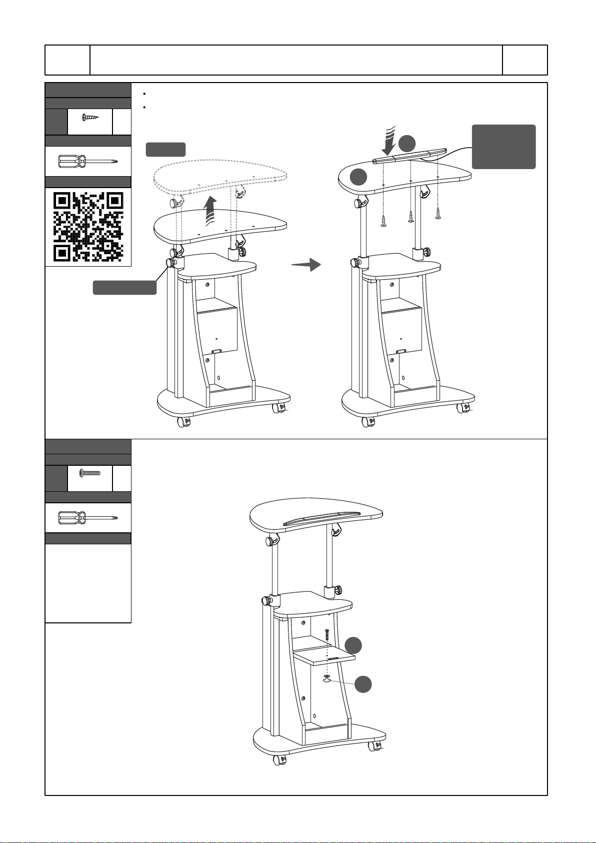
Lift the main panel 12 about 6inches and tighten the screw knobs 16.
Assemble the protection rail 15 to the main panel 12 with its curvature towards
the front with screws Bfrom underneath.
STEP 12
Hardware
BM5x16 3
Pcs
Tighten 16
12
15
18
19
Tools (included)
Scan QR to view step
Assemble the handle 19 to the door 18 with screw G.
STEP 13
Hardware
GM4x20 1
Pc
Tools (included)
Scan QR to view step
Lift 12 Curvature
towards
the front
Give yourself a nice pat on
the back, you did a great job!
P.12 P.12
RTA-B005
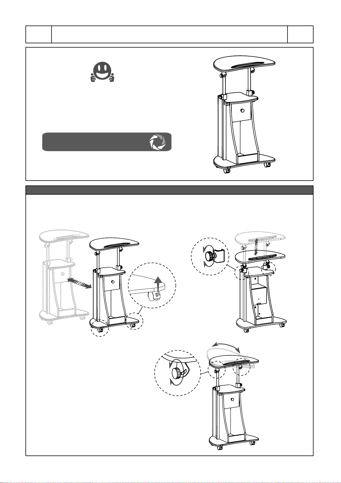
ALL DONE!
ENJOY YOUR NEW UNIT!
FUNCTIONS / ADJUSTMENTS
ROLLING:
Unlock the front casters to
allow free movement.
LIFTING:
Loosen the screw knobs to lift,
then tighten again.
TILTING:
Loosen the screw knobs to tilt,
then tighten again.

P.13 P.13
RTA-B005
Clean the surfaces preferable with a clean cloth damped in a solution of mild soap and water,
then dry with a clean towel.
If you decide to use a cleaning agent, test first on an area hidden from view such as
underneath the tabletop.
Every 4 months, inspect the unit completely and make sure that all screws are tighten.
When transporting the unit to places far away, protect and secure the unit to avoid damage in
transit.
Shall any part of the unit become defective during the warranty period, replacement parts
might be available to you at no charge. Please refer to the last pages on this manual.
The warranty does not extend to regular wear and tear, nor the manufacturer assumes liability
for damages or consequences due to accidents, incorrect assembly, negligence, improper
use, modifications, or not heeding the above warnings.
WEIGHT LIMITS
CARE AND MAINTENANCE
WARNINGS
Do not exceed the indicated weight limits.
Do not expose the surfaces to direct sunlight or to extreme environmental conditions.
Do not use solvents or abrasive materials to clean the unit.
Do not climb on the base of the unit.
Do not allow small children to play with the unit.
Before moving the unit, unlock the front casters and make sure to secure or remove any object
on it that might fall off.
Do not overtighten the screw knobs.
Make sure that the tilting mechanisms are properly assembled as instructed in page 9 step 9.
An incorrect assembly leaves the tilting mechanism unsecured, and the main top panel will not
hold enough weight on it and even might flip down forwards unexpectedly.
If you have objects or devices on or under the main panel, use caution when adjusting the
height or tilting angle.
It is recommended to first tilt the main panel, then place the objects or devices, but pay
attention to if they will be properly retained by the protection rail. If the object or device seems
that might tip over, reduce the tilting angle.
Do not use the unit if the plastic covers or screw knobs look cracked or if they are stripped.
20 Lbs
(9.1 Kg)
20 Lbs
(9.1 Kg)
20 Lbs
(9.1 Kg)

P.14 P.14
RTA-B005
TECHNI MOBILI WARRANTY
RTA Products, LLC warrants to the Original Purchaser who acquired a new product from RTA
Products or its authorized resellers that this product will be free from defects in its workmanship
and materials, under normal use and service conditions, as described herein. "Defects" as used
in this warranty, is defined as any imperfections that impair the use of the furniture or product.
RTA Products LLC will replace any defective part, at its discretion, and without charge to the
original purchaser other than the freight from the end consumer to RTA Products.
Replacement parts can only be supplied if parts are available. Items out of production may be
unavailable. This warranty will be effective for the applicable time period beginning the date of
purchase on your original sales receipt. RTA product’s obligation under this warranty is limited to
repairing or replacing products or parts as provided herein. This product has been designed for
and is intended for office and home-office use only. This warranty is Original Purchaser’s sole
remedy for product defects, and this warranty does not extend to any product, or damage to any
product, caused by or attributed to abuse or misuse, products used for commercial or rental
purposes, use modifications of, or attachments to the product, and products or parts not used,
maintained, or extended hereunder is in lieu of any and all other warranties, express or implied,
including without limitations any implied warranty or merchantability or of fitness for a particular
purpose. Please note, all desks made with PVC Laminate surface should not be exposed to
direct sunlight, as it may damage the material. Damage of this nature is not covered under this
warranty.
RTA Products will not be responsible for indirect, special, incidental or consequential damages.
This warranty is limited to merchandise purchased in the Continental United States, excludes
AK, HI and PR. Some States do not allow the exclusion or limitation of incidental or
consequential damages, so the above limitations or exclusions may not apply to you. This
warranty gives you specific legal rights. You may also have other rights that may vary from state
to state.
RTA Products will advise you of the procedure to follow in making warranty claims. The following
are the procedures for warranty claims:
a. Call us Monday – Friday, from 9am-5pm (Eastern Time) at (866) 782-5520 to explain the
defect and give your name, address and phone number. Please have ready the model number
of our product, date and place of purchase. You can also write to us by e-mail to
b. If we determine that replacement will remedy the situation, and in order to determine the
extent or the cause of the defect, purchaser will need to send the part in question at purchaser’s
expense. Once we receive the part, we will examine it and determine whether the claim is valid
(or not), and then proceed to send the replacement. We will ship the replacement at our
expense.
DESKS/LAPTOP CARTS/FILE CABINETS: LIMITED 5-YEAR WARRANTY

FOR SEVERAL HELP OPTIONS
INCLUDING REPLACEMENT PARTS ORDERS
VISIT: WWW.TECHNIMOBILI.COM
AND CLICK ON SUPPORT TAB
Or scan the following QR Code:
Scan the following QR Code to order replacement parts:
EMAIL US:
Other manuals for RTA-B005
1
Table of contents
Other Techni Mobili Outdoor Cart manuals


Popular Outdoor Cart manuals by other brands


Vestil
Vestil CART-500-2033-FP instruction manual

Costway
Costway OP70393 user manual

EefaCo.Store
EefaCo.Store PROTEAK 701 Assembly instructions

Amity Technology
Amity Technology Concord 2250 Owner's operating manual

Black cat
Black cat MH1100-1 owner's manual

Gorilla Carts
Gorilla Carts GOR10-16 quick start guide


