manuals.online logo
Brands
  1. Home
  2. •
  3. Brands
  4. •
  5. Technics
  6. •
  7. Amplifier
  8. •
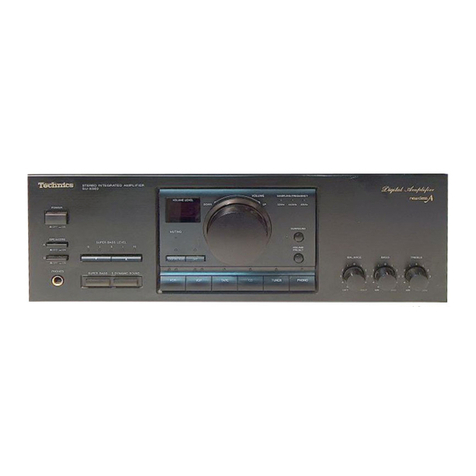
  9. Technics SU-V460 User manual

Technics SU-V460 User manual

Other Technics Amplifier manuals

Technics SU-V36 User manual

Technics

Technics SU-V36 User manual

Technics SU-V3 User manual

Technics

Technics SU-V3 User manual

Technics SU-V5 User manual

Technics

Technics SU-V5 User manual

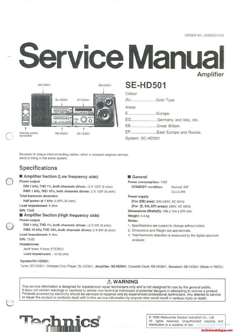
Technics SE-A800S - service Instruction manual

Technics

Technics SE-A800S - service Instruction manual

Technics SU-V500M2 User manual

Technics

Technics SU-V500M2 User manual

Technics SA-CH950 User manual

Technics

Technics SA-CH950 User manual

Technics SU-A60 User manual

Technics

Technics SU-A60 User manual

Technics SU-A808 User manual

Technics

Technics SU-A808 User manual

Technics SE-A900S User manual

Technics

Technics SE-A900S User manual

Technics SU-C700A User manual

Technics

Technics SU-C700A User manual

Technics SU-G700 User manual

Technics

Technics SU-G700 User manual

Technics se-ch570 User manual

Technics

Technics se-ch570 User manual

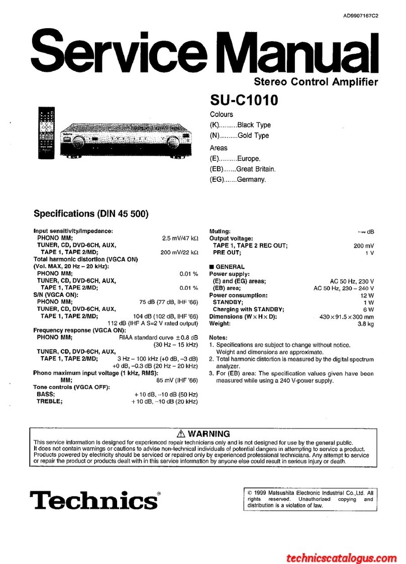
Technics SU-C1010 User manual

Technics

Technics SU-C1010 User manual

Technics SA-CH950 User manual

Technics

Technics SA-CH950 User manual

Technics SA-DV250 User manual

Technics

Technics SA-DV250 User manual

Technics SEA1010 - STEREO POWER AMPLIFI User manual

Technics

Technics SEA1010 - STEREO POWER AMPLIFI User manual

Technics SU-GX70 Assembly instructions

Technics

Technics SU-GX70 Assembly instructions

Technics SA-EH770 User manual

Technics

Technics SA-EH770 User manual

Technics SU-V90D User manual

Technics

Technics SU-V90D User manual

Technics SU-V85A - service User manual

Technics

Technics SU-V85A - service User manual

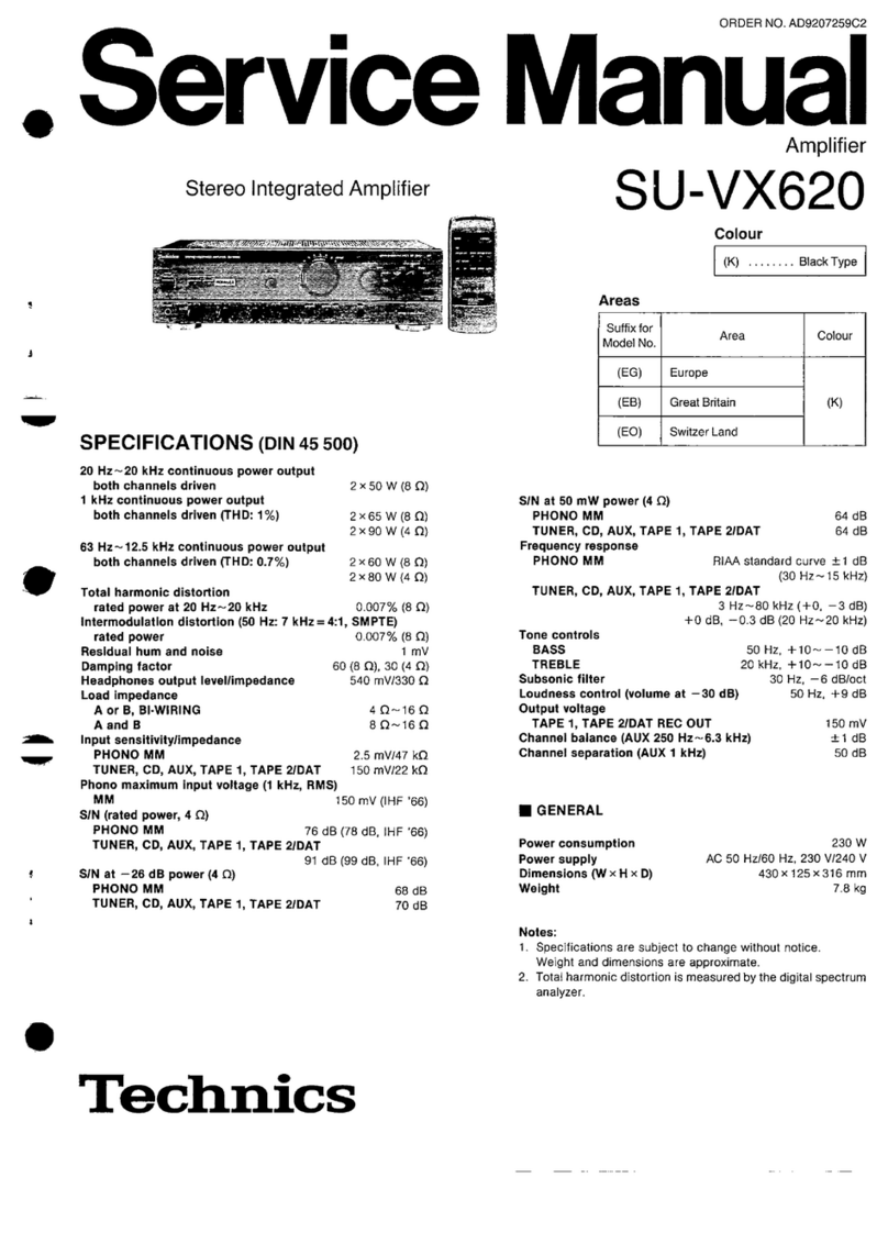
Technics SU-VX620 - service User manual

Technics

Technics SU-VX620 - service User manual

Technics SU-V90D User manual

Technics

Technics SU-V90D User manual

Technics SE-CH530 User manual

Technics

Technics SE-CH530 User manual

Technics SU-V300M2 User manual

Technics

Technics SU-V300M2 User manual

Popular Amplifier manuals by other brands

Magnat Audio EDITION FOUR Owner's manual/warranty document

Magnat Audio

Magnat Audio EDITION FOUR Owner's manual/warranty document

Inter-m PA-2000A Operation manual

Inter-m

Inter-m PA-2000A Operation manual

Yamaha TX6n owner's manual

Yamaha

Yamaha TX6n owner's manual

Peavey TNT 150 user guide

Peavey

Peavey TNT 150 user guide

Bosch LBB 1903/10 Installation and user instructions

Bosch

Bosch LBB 1903/10 Installation and user instructions

Avocent Emerge DA1200D Installer/user guide

Avocent

Avocent Emerge DA1200D Installer/user guide

Redgum RGi35 operating instructions

Redgum

Redgum RGi35 operating instructions

Cambridge Audio AXA25 user manual

Cambridge Audio

Cambridge Audio AXA25 user manual

Alpine MRP-M200 owner's manual

Alpine

Alpine MRP-M200 owner's manual

Technical Pro H1502UrBT user manual

Technical Pro

Technical Pro H1502UrBT user manual

FMS EMGZ307 operating manual

FMS

FMS EMGZ307 operating manual

Racal Instruments 5601 user manual

Racal Instruments

Racal Instruments 5601 user manual

Valcom V-1094A Technical specifications

Valcom

Valcom V-1094A Technical specifications

Cambridge Audio 851D user manual

Cambridge Audio

Cambridge Audio 851D user manual

QSC 3800 Specifications

QSC

QSC 3800 Specifications

NAD C300 owner's manual

NAD

NAD C300 owner's manual

Rotel RMB-1077 owner's manual

Rotel

Rotel RMB-1077 owner's manual

Peavey Monitor 300 Series operating guide

Peavey

Peavey Monitor 300 Series operating guide

manuals.online logo
manuals.online logoBrands
  • About & Mission
  • Contact us
  • Privacy Policy
  • Terms and Conditions

Copyright 2025 Manuals.Online. All Rights Reserved.

Service
Manual
Stereo
Integrated
Amplifier
SPECIFICATIONS
(DIN
45
500)
@
AMPLIFIER
SECTION
20
Hz~20
kHz
continuous
power
output
both
channels
driven
2
x
45
W
(8
Q)
1
kHz
continuous
power
output
both
channels
driven
(THD:
1%)
2
x
60
W
(8
Q)
2
x
85
W
(4Q)
63
Hz~12.5
kHz
continuous
power
output
both
channels
driven
(0.7
%)
2
x
55
W
(8
Q)
2x
75
W(4Q)
Total
harmonic
distortion
(Power
Amp
Direct
input)
rated
power
at
20
Hz~20
kHz
0.005
%
(8
Q)
rated
power
at
1
kHz
0.0009
%
(8
Q)
0.002
%
(4
Q)
half
power
at
20
Hz~20
kHz
0.005
%
(8
Q)
half
power
at
1
kHz
0.0009
%
(8
Q)
0.002
%
(4
Q)
Intermodulation
distortion
rated
power
at
50
Hz:
7
kHz=4:1,
SMPTE,8Q
0.007%
Residual
hum
and
noise
0.2
mV
Damping
factor
60
(8
Q),
30
(4
Q)
Headphones
output
level
and
impedance
540
mV/330
Q
Load
impedance
AorB
4Q~169
A
and
B
8Q~162
Input
sensitivity
and
impedance
PHONO
MM
2.5
mV/47
kQ
TUNER,
CD,
AUX,
TAPE
1,
TAPE
2/DAT
150
mV/22
kQ
POWER
AMP
DIRECT
1V/18
kQ
Phono
maximum
input
voltage
(IHF
’66,
1
kHz,
RMS)
MM
150
mV
S/N
rated
power
(4
Q)
PHONO
MM
76
dB
(IHF
'66:
81
dB)
TUNER,
CD,
AUX,
TAPE
1,
TAPE
2/DAT
97
dB
(IHF
'66:
100
dB)
Technics
ORDER
NO.
AD8905140C8
Amplifier
SU-V460
Color
(S)...Silver
Type
(K)...Black
Type
Area
Country
(E),
(E5)
|
Continental
Europe
E
POWER
AMP
DIRECT
—26
dB
power
(4
9)
106
dB
(IHF
'66:
115
dB)
PHONO
MM
75
dB
TUNER,
CD,
AUX,
TAPE
1,
TAPE
2/DAT
84
dB
50
mW
power
(4
Q)
PHONO
MM
75
dB
TUNER,
CD,
AUX,
TAPE
1,
TAPE
2/DAT
78
dB
Frequency
response
PHONO
RIAA
standard
curve
+0.8
dB
(30
Hz~15
kHz)
TUNER,
CD,
AUX,
TAPE
1,
TAPE
2/DAT
3
Hz~100
kHz
(—3
dB
+0
dB,
—0.2
dB
(20
Hz~20
kHz
2
Hz~120
kHz
(—3
dB
+0
dB,
—0.2
dB
(20
Hz~20
kHz
POWER
AMP
DIRECT
Tone
controls
BASS
50
Hz,
+10
dB,
—10
dB
TREBLE
20
kHz,
+10
dB,
—10
dB
Loudness
control
(volume
at
—30
dB)
50
Hz,
+9
dB
Output
voltage
TAPE
1,
TAPE
2/DAT
REC
OUT
150
mV
Channel
balance,
AUX
250
Hz~6,300
Hz
+1
dB
Channel
separation,
AUX
1
kHz
50
dB
HB
GENERAL
Power
consumption
450
W
Power
Supply
For
Great
Britain
and
Oceania
AC
50
Hz/60
Hz,
240
V
For
Continental
Europe
AC
50
H2/60
Hz,
220
V
For
others
AC
50
H2/60
Hz,
110
V/127
V/220
V/240
V
Dimensions
(W
x
H
x
D)
430
x
125
x
320
mm
(16-15/16"
x
4-15/16"
x
12-5/8")
Weight
8.0
kg
(17.6
Ib.)
Notes:
1.
Specifications
are
subject
to
change
without
notice.
Weight
and
dimensions\are
approximate.
2.
Total
harmonic
distortion
is
measured
by
the
digital
spectrum
analyzer.
Matsushita
Electric
Industrial
Co.,
Ltd.
Central
P.O.
Box
288,
Osaka
530-91,
Japan
@
CONTENTS
Page’
Page
BEFORE
REPAIR
AND
ADJUSTMENT
...............-..--
2
PRINTED
CIRCUIT
BOARDS.
................0
0000
cee
11
PROTECTION
CIRCUITRY
i
siivosics
cuccewamaninnsscneaee
eee
2
TERMINAL
GUIDE
OF
IC’S,
ACCESSORIES)
iis
tains
cass
enetod
ads
ceevanny
edenees
dae
2
TRANSISTORS
AND
DIODES
....................0200.,
15
LOCATION
OF
CONTROLS
.............
20000
e
eee
eee
eee
3
BLOCK
DIAGRAM
}
sdiicoanareeacne
gmimnset
ecpare
creme
Sandee
owas
15
DISASSEMBLY
INSTRUCTIONS
..................0
0.02206.
“
MEASUREMENTS
AND
ADJUSTMENTS
...............-..
17
SCHEMATIC
DIAGRAM
.........2..00.
000
c
cece
eee
eee
7
REPLACEMENT
PARTSLIST
...................00008
18
WIRING
CONNECTION
DIAGRAM
...................02005
10
EXPLODED
VIEW
4
sdaspnies
sayin
n
cenne
noaardaaiewsns
eaawaled
#
22
m
BEFORE
REPAIR
AND
ADJUSTMENT
(1)
Turn
off
the
power
supply.
Using
a
109,
10W
resistor,
shortcircuit
both
ends
of
power
supply
capacitors
(C705,C706)in
order
to
discharge
the
voltage.
(2)
Before
turning
on
the
power
switch
of
the
unit.
A.
Connect
the
voltage
controller
to
the
primary
side.
B.
Connect
the
AC
ampere
meter
to
the
primary
side
or
connect
the
DC
voltage
meter
to
the
“+B”
circuit
of
the
secondary
side.
C.
Turn
the
VR
of
ICQ
(VR451
and
VR452)
to
minimum
(counterclockwise).
D.
After
setting
the
output
to
zero
of
the
voltage
contoller,turn
on
the
power
switch
of
the
unit.
And
increase
the
output
of
voltage
controller
gradually.
Then,
check
carefully
whether
the
current
value
of
primary
side
become
more
than
following
value
or
whether
the
DC
voltage
of
secondary
side
is
increasing
slowly.
E.
If
the
value
of
current
is
increasing
unusually
or
the
DC
voltage
is
not
increasing,lower
the
output
level
of
voltage
contoller
immediately.
@
The
current
value
of
the
primary
side
at
no
signal.
(Confirm
the
power
supply
voltage
of
each
area
and
provided
voltage
of
the
unit.)
Power
supply
voltage
AC110V
AC
120
V
AC
220
V
AC
240
V
So
cocenilieirieah
120~480mA
|
110~441mA
60~240
mA
55~220
mA
114~456mA
|
104~417mA
56~227
mA
52~208
mA
,
-
@
PROTECTION
CIRCUITRY
The
protection
circuitry
of
the
amplifier
may
have
If
this
occurs,
follow
the
procedure
outlined
below:
operated
if
either
of
the
following
conditions
is
noticed:
1.Turn
off
the
power.
@
No
sound
is
heard
when
the
power
is
turned
on.
2.Determine
the
cause
of
the
problem
and
correct
it.
@
Sound
stops
during
a
performance.
3.Turn
on
the
power
once
again.
The
function
of
this
circuitry
is
to
prevent
circuitry
damage
if,
for
example,
the
positive
and
negative
speaker
Note:
connection
wires
are
“shorted”
,
or
if
speaker
systems
with
When
the
protection
circuitry
functions,
the
unit
will
not
an
impedance
less
than
the
indicated
rated
impedance
operate
unless
the
power
is
first
turned
off
and
then
of
the
amplifier
are
used.
on
again.
mm
ACCESSORIES
e@AC
power
supply
Cord
............ccee
ee
eee eee
eeee
1
@AC
plug
adaptor
..........
2.
ccc
cece
cece
eee
eee
1
(SFDACO5E03)..........
For
(E),
(E5)
and
(EG)
areas.
(SUP9215)
..............
For
(GC)
area
only.
(SJA193)
..............
For
(EB)
area
only.
(RJAO0004)
..............
For
(GC)
area
only.
(SJA173)
......
eee
ee
eee
For
(GN)
area
only.
m
LOCATION
OF
CONTROLS
eFront
Panel
=,
root
te
[6]
[9]
(8) [7]
[1]
Power
switch
(power)
|7|
Mode
selector
(mode)
[2]
Operation
indicators
[8]
Loudness
switch
(loudness)
(amplifier
operation
monitor)
9|Tone
control
switch
(tone
control)
'3|Power
amplifier
direct
switch
10]
Balance
control
(balance)
(power
amp
direct)
11]
Tone
controls
(bass/treble)
[4]
Volume
control/indicator
(volume)
CS
[5]
Input
selector
(input
selector)
12|
Speaker
selectors
(speakers)
[6]
Recording
output
selector
(rec
selector)
13}
Headphones
jack
(phones)
e
Rear
Panel
-—
PLAYBACK
REC
OUT—>
TAPE
|
TAPE2/
DAT
REC
OUT)
7PLAYBACK-
ree
ae
POWER
AMP
AC
OUTLET
TUNER}
AUX
DIRECT
fans
wee
only
AC
INLET
al
>)
A}
ma In
()
—
SPEAKER
O
Gir
scone
we)!
VOLTAGE
SELECTOR
for
(GC)
area
only
*Phono
input
capacitance
is
about
270
pF
for
EG
area
(about
100
pF
for
other
areas).
=
DISASSEMBLY
INSTRUCTIONS
1.
Remove
the
2
screws
(@,
@).
2.
Remove
the
shield
plate
(R).
3.
Remove
the
3
screws
(@~@).
Procedure
_—CNIO2
1523
Remote
Switch
Controller
Front
Panel
4.
Remove
the
2
connectors
(CN101,
CN102).
;
ae
5.
Remove
the
remote
switch
controller.
f
menos
ineipower-sallich
Duan
by
puSning
tien
6.
Remove
the
front
panel
in
the
direction
of
the
arrow.
behind
the
front
panel.
2.
Remove
the
2
screws
(@,
@).
@
Removal
of
the
remote
switch
controller
3.
Release
the
1
claw.
aRciwve
the
4claws
Procedure
Remote
Switch
|
Controller
~_
1-24
Replacing
of
the
remote
switch
controller
1.
Fully
rotate
the
Recording
Selector
Control
counterclockwise.
2.
Push
the
Switch
Slide
in
the
direction
of
the
arrow.
Lever
Switch
Slide
%%™
Removalofthe
LEDP.c.B.
©
1.
Remove
the
1
screw
(@).
2.
Release
the
2
claws.
Removal
of
the
headphones
P.C.B.
1.
Remove
the
2
screws
(@,
©).
2.
Release
the
1
claw.
Rec
Selector
Knob
a
Removal
of
the
volume
P.C.B.
Removal
of
the
operation
P.C.B.
Procedure
Procedure
1-2-5
Volume
Knob
EA
Connector
1.
Pull
out
the
volume
knob.
2.
Remove
the
nut.
3.
Release
the
1
claw.
1.
Pull
out
the
4
knobs
(O~@).
2.
Remove
the
4
nuts
(@~®).
Procedure
1-27
Rec
Selector
Knob
|
—Main
P.C.B.
Front
Panel
5.
Remove
the
bottom
chassis
in
the
direction
of
the
arrow
1.
Pull
out
the
rec
selector
knob.
eUseawrenchofthe
A:
11mm
a
jens
2.
Remove
the
nut.
dimensions
shown
in
B:
16mm
.
Remove
the
3
screws
(@~@).
7
.
3.
Remove
the
remote
switch
controller
in
the
direction
of
the
the
illustration
above
—C:_
longer
than
4.
Remove
the
front
panel.
6.
Reinstall
the
front
panel
to
the
main
P.C.B.
arrow.
to
remove
nuts.
22
mm
a
|
Removal
of
the
power
IC
—
Removal
of
the
power
transformer
Procedure
+
eee
.
Procedure
i
nsolder
the
power
IC.
Procedure
Procedure
Leaded
2.
Remove
the
Sens
(@,
@).
ladda
1-8
;
1-9
Power
IC
__
Shield
~~
Plate
(R)
Shield
Plate(L)
—
Nac
IN
P.C.B.
Power
Transformer
e@When
mounting
the
power
IC,
apply
silicon
thermal
compound
(SZZOL15
or
equivalent)
to
the
rear
of
the
power
e@Remove
the
5
screws
(Q@~@).
eRemove
the
4
screws
(@~@).
e@Release
the
2
claws.
IC.
ZY
exon
EQ/TONE
AMP
CIRCUIT
VOLUME
CIRCUIT
(UVOLUME
J°=
= =
==
a
SI
a
SE
SS
Ee
Ne
eee
Nl
a
EOS
A
a
a
eer
~~
-
—
r
--1VOLUMEI-~
~~
~~
7
:
vR20I-1
vR201-2
vR201-4
vR201-3
401,402
wl
100K
A
100K
&
’
}
20K
8
20K
8
2SAN23RST
Lye.
nx
«
a
rt
PRE
DRIVE
+E
B%
2
eaigG
tne
t
7
sh
Ed
am
2/46
Paanen
|
3
rd
|
;
Wy
PAV)
6307
Tel
-
|
t
50V4.7
313,
|
=eS5%
tl
|
ed
aeE
a
oA
a
:
me
|
DOOOT
|
DOOOO
301
R301
-305
|
2
ES
L
C305
|
R305
=
>
,
|
€109,
110
|
f
50V33
BaP
|
220K
Stk
|
cnaoni2)
:
a
-
|
©
(EG)
.
0.001
|
le
cP2oiti/2)
a
(others)
-390P
W
|
£
|
AN6558F
—
—~
PHONO
EQ
AMP
|
L
|
is
-
_|
(POWER
ame
Gael
|
al
zSx=
“9k
|
;
|
|
ase
(eset,
7
|
28
6
|
530,
|
,
AN7062N
ke
=
|
Ure
BLOG
|store
aoa
(TONE
————
VOLTAGE
AMP
}
.
|
—
li
fal
ss
x
|
52
o
|
contro)
CP103
|
chia
116
5)
LI
L
|
<
he
|
es
3
Q
R316
|
|
V4
2)—(3)
14)
(5)
(6
47
8)
49
%
jpoesenanstemmse
Pd
Seay
=
|
|
|
OV
“T-OIVT-OIV
Yaav
Ta2v
“aay
“4isv
74220743.
1V
|
——
|
i
”
|
|
coef
a
|
mF
@
=
2
iy
|
[
ot
|
<<
=
qT
|
t
-
—
|
|
[-
kl]
oH
sz|
|
32
3
|
|
22k
|
iz
&
aur
PF
had
ace
&
Bl
|
gig
T
302
R302
TS
zal
|
—e
ile
§=6
ge
3
S73
——
|
“|
7
878
ee}
=|
|
ay
-—4
$044}
ewe
a
‘|
|
es
e-
8
R
i
|
+
e
ae.
|
:
Lies
guested
oles
slate
|)
eae
fig
case
|
€208)
305
\ss—tet
*
|
le
|
R219
SROANN
off——eon
5103-3
‘ame
|
308
&
csi!
St}
|
cPioa4|
@
|
ea:
—
s
oe
:
4
‘
-/
|€
T
|
Fy
7]
!
4K}
+t
+e
el,
=p
|
|
\
|@O
|
Ls
|
$103-2
.
1
{
|
R320)
©
2m
B
Fi
|
3)
:
|
Ti
ie
Loa
|
LJ
(mMooe)
|
1
-
:
|
oa)
+
4}
—
Sa
|
2
|=
A
4
igs
q
1
a
220}
cote
R212
|
fa
Fm
|
(EG)
ae
7
2
er
a
xy
o
eS
area
4
_
=
—<
8B
:
iL.
R216
&
5
|
;
=
|
|
a
cmestaai
aan
me
S101
Sar
R220
|
|
‘
KINPUT
SELECTOR)
rt
4
5
~
4
|
|
1
|
ae
TAPE
2/DAT
oe
=
as
a
=
_
_
a
ws
-
_A
ae
7
16.6¥
'
2
a .
7
3
A
iis
TUNER
|
'
J
a
ee
ee
eS
ane
a
ee
]
|
|
—er
te
bee
7
ea
——
——
—=
a
-
=
—J
|
|
-
ee
:
1
|
|
CN103
)
cn104
AGNI
OS
RCN401
A,
/
pee
|B
|
MAIN
CIRCUIT
——
SEN
IOY
‘CN102/—
:
/
\
(DOO)
OOO
aml
SESHSTT
SSS
5)
@®
ap97o>
UKIOI-I
‘i
§
g
t
baal
0453,454
0457,
458
0463,
464
0461,462
Alcsol
@50!
GND
CeGJarea.
ey]
|
|
:
2SC33IIAQSTA
2SC263IRST
2SAI535AQRS
2SC3944AQRS
SV13205
2SA992EFP
,
:
:
:
Phono
|
| |
|
|
|
|
|
LIMITER
AA
CLASS
AMP
AA
CLASS
AMP
AA
CLASS
AMP
POWER
AMP
RELAY
DRIVE
|.
|
|
q|
|
!
0465,
466
min
uk
ioi-2
#
8
signal
(Loh)
||
|
|
|
I]
|
\
2SCI685RST
gem
laos7
FP
A
r!
H(
Se
8
|
|
|
|
|
ICQ
ADJ.
OSS
Ch)
gy
A
a
ii
i
PHON
<
i
Ha
|
ee
Os
TU
rk
Se
rere
ee
teeereeweeeee
wecere
cures
weeeevecerey
(weerrs
crenc.
PHONO
:
a
=
=
|
|
|
}
|
|
S
Seepececsteceteeteesteenmngnennonmeniamenatnnatini
ire
R
CH(G
—
oF
Riz
>
D
4
|
|
Poy
po
ge
PCB
ee
|
ass
YL
LS
A
WH
3)
>.
yO
2
°
+-—
|
11]
;
food
¥
~aaev
Ev
TOV
“av
Tok
raw
ey
=
l
Reon
[ee
<a
|
I)
|
A
ta
5a
eel
|
a
JKIOI-3
=
|
|
|
&
a
aS
pb
H@
Tag
;
|
|
|
|
|
<ef
|
|
“tL
°3
TUNER
4
cw
R202
|
|
|
|
|
Aa
~
Treza
+2
cH@
+8
|
|
|
|
edi
San
a:
|
|
c
|
820K
MAST
BOMT|A
jis
7
tagatshins
we
Sme
ted
vez
|
ata
|
||
iyi
|'9.2%—
3g
<
sats
oi
pl
CH(
+88
eel
|
|
j
|
(Len)
zs
g
Sg
§
|
|
|
q
-
—tt{}
|]
|}
FP
Fy
PpP
fy
Psy
ya
Tf
Be
ag,
8
Pf
REIT
|
peteteeneese
vio2-2ll
Ts
|
7
|
Y
|
2¢5
"C525
R533
pl
CHO
Si
oH
i
|
|
|
|
|
|
a39v
ZL
ne
q
|
0.0027
1.8K
|
AUX
<
i
|
J
|
|
{|
22
pew
:
Lr
cHG
rt
|
4
44
4
ea
|
me
:
1
qs
|
|
le
2
"
A
ies
or
we
acdsee
i
|
We
|
soa
8s
JK
IO3-1
T
a
a
ae
jag
es:
pk
CHE
=
Q455,456
|
Voltage
control
|
jee
hae
cz
2s
rec
urd
|
=
ossia82
3
FaAregones™
vamp
feo
oa)
|
eee)
188
|
“Re
CHG
|
|
2SC263IRST
|
Y
point
LL
iss
38_|
723I|
|
TAPEI<
|
|
rT
CURRENT
|
|
|!
Loeh,+
2-Leh-,]_o
1
|
[es
Sst!
[8g
vkI08-2-
| 1
STABILIZER
Vere!
]
ov
es
°
Rch,-4-R
cht
:
|
|
(ca
T
=F
max
ft
S
i
||
||
|
eee
be]
os
eel
|
BACK
\
|
control
amp
:
=
R
CH
+
|
lice
adj.
Py
Arsis
(E8,GN)
areas.
|
.
}
N
ukioa-1
4
|
|
lor
ch)
=
|
cs26
R534
|
|
1
-L
CHORE
|
|
4}-—-wn-+
—
—e—
[EB,GNJareas.
a
rec
out
<
a
14
|
—
5!
sil)
A
_
lf
4
oe
enrol
J
|
+
,;
8
TO
+
Sea
[
4
im
j
|
|
|
|
Rso2
|
RSO6
=
usoz esio
Arsiz
|
LSo4
o
8
‘|
|
TAPE2
/DAT
+
seioasel
4
|
Le
2
a
8
3
|
|
ea
Va
‘a
|
-L
CHO)
TT
|
+
|
|
2459,
460
So
ms
&
Arszo
|
Qj!
+8
|
ry
‘
play
JS
|
if
$102
|
+4
2SA1123RST
=
e
2
°
e/|
{2
|
|
BACK
LR
cHO
|
L
(REC
SELECTER)
AB
|
|
is
|
soe,
AA
CLASS
AMP
};
3 3
£
|
|
|
3s
|
—
|
TAPE
2/087
»
TAPE
|
|
!
==
|
ukiosll
2
-TAPE
|»
TAPE
2/0aT
es
wie
=
-L
CHO
Aife
|
J
|3-co
|
$25
os
P
POWER
AMP
Bi
e
o.
|
‘
Tuner
|
|
72:
pa
co
DIRECT
roc
om
8
ey
6
AUX
|
\~
e
|
yt
|
a
ee
wal
4
5V
eee
See
RS
—
7
8 9
10
11
12
13
Power
Source
For
(GC)area.
a
a
a
ae
a
a
ee
hoe
ee
p_
vR201~4
vR201-3
401,402
POWER
SWITCH
—
eorok®
20K
8
2SA1l23RST
CIRCUIT
PRE
DRIVE
14
15
16 17
m
SCHEMATIC
DIAGRAM
(Parts
list
on
page
18~21)
(This
schematic
diagram
may
be
modified
at
any
time
with
the
!
naa
|
ae
oe
development
of
new
technology.)
if
:
Es
a
|
AS!
o.082
TeSne
N
.
t-—H4
88
&
aren
lotes:
248
FI
os
plitra
SELECTOR
pee
|
eS1
:
Power
switch
in
“on”
position.
“Teata]
CIRCUIT
laa
,
_
eS2
:
Voltage
selector
switch
in
“‘220
V”
position.
is
tuamien
nee
]
L-
-J
G
AC
_IN/AC
OUTLET
for
iGC\
area
ont
5
sS8¢—B—
PS
1
At
Nis
=
-
CIRCUIT
‘or
(GC)
a
ye
7
A
1
|
=
lee
cen
teme’s
eS101
~~:
Input
selector
switch
in
“phono”
position.
es
=af
Tea
:
i
ws
WB
A
.
.
°,
way
sar
|e:
:
Meals
J
r)
|
6
ts
KI
S102
=:
Recording
output
selector
switch
in
“tape
2/
t
sorueden
sen
an
ber
Wr,
wit
re
|g
Paes
FA
4]
ai
4
ac
IN
DATP
1”
position.
ce
16401
|
48
ie
ee)
S|
AGaeoe
3
=|
A
ster
20/200
©S103-2
:
Mode
selector
switch
in
‘‘stereo”
position.
diets
on
fon
af
a
Tecomne
Aue
H
UY
ale
TA
ie
agezey
|
©S$103-3
:
Loudness
switch
in
“off”
position.
BF
9
|
contaon:
FF
|
vo
Tac
ouriers
eS301
:
Tonecontrol
switch
in
“defeat”
position.
JyL
Lf
OO
OO
—O—D—O—@
=
S302
:
Power
amplifier
direct
switch
in
“off”
position.
eal
|
POWER
SWITCH
:
@$501-1
:
Speaker
(A)
selector
switch
in
‘‘on”’
position.
Tt
=r
as:
++
.
CIRCUIT
eS501-2
:
Speaker
(B)
selector
switch
in
“off”
position.
:
Negative
voltage
lines.
:
Phono
Signal
(Lch)
:
Recording
Signal
—
>—
:
Positive
voltage
lines.
'
e|ndicated
voltage
values
are
the
standard
values
for
the
unit
measured
by
the
DC
electronic
circuit
tester
(high-impedance)
with
the
chassis
taken
as
standard.
Therefore,
there
may
exist
some
errors
in
the
voltage
values,
depending
on
the
internal
impedance
HEADPHONES/
SPEAKER
SWITCH
CIRCUIT
7,458
463,464
461,462
Alcso!
Qsol
:263IRST
2SAI535AQRS
2SC3944
AQRS
FP
.
ZLASS
AMP
AA
CLASS
AMP
AA
CLASS
AMP
Mil
S205...
ie
BEI
C
EEE
Phono
signal
(Lch)
(EG)areas.
«502
2
Daal
<
:
=
.
=
NA
N
aS
a
3
c
as
BSS
W505
<ig
|°s
w
S07
mo
ye
—_—___—_—
wsos
3
-
hy
als
—()|w50s
———_—__—-
wo
az
ke°
35
z
Be=35
4
age
H
TA)
H
(8)
’
=
SPEAKERS
t
‘ep
wok
RCH
(A)
|
=
3g
_
=o
H
(By
>
~
|
Ree
Voltage
control
$52
>
ey
E
POWER
SWITCH
amp.
ICQ
adj
sue
ee
CIRCUIT
point
|
jos
Aig
8
eee,
IMSS
fe
ee
Pree
<
#58
eames
0701~
704
°
Rch,-4
Recht
aS
aS
|
|
_
|
a
0
P3000LF
“
=|
|
¢526
R534
H
4
J
\
|
AC
IN
CIRCUIT
A
°
+
i
are
sw
8
ol
:
3g
r—e_t-
-
|
Z|
Ls0o2 resio
Arsiz
L
42
o701A
=
a
ms
—
|
|
pe
ew
inal
ed
Sad
2459,
460
35
hs
|
|
A
|
E601
:
3
2
7S
T
a
I
|
SL
Aso:
|
Gtners)~
0.01
|
A
2SAIl23
RST
iba
i]
of
Fi
cee
1/2W/12
i
AA
CLASS
AMP
Sq
Arsia
|
i
Sia
@])weor
/
LED
=
|
|
iB
‘
d
CIRCUIT
i
|
|
we
i
;
L
|
A
7
Se
SS
eS
lh
Gi
ete
tsiia
dials
fr
;
—_
ee
|
tnoiser2eH
AC
IN
CIRCUIT
0703
LNOI8472PH
(
4
. 7
‘i
|
oo
Por
of
the
DC
circuit
tester.
<
{220v
So/6OH)
Important
safety
notice:
:
Components
identified
by
“\,
mark
have
special
characteristics
important
for
safety.
When
replacing
any
of
these
components,
use
only
manufacturer’s
specified
parts.
*Caution!
IC
and
LSI
are
sensitive
to
static
electricity.
Secondary
trouble
can
be
prevented
by
taking
care
furing
repair.
*Cover
the
parts
boxes
made
of
plastics
with
aluminum
foil.
*Ground
the
soldering
iron.
*Put
a
conductive
mat
on
the
work
table.
“Do
not
touch
the
legs
of
IC
or
LSI
with
the
fingers
directly.
AC
IN
240V-~
(EB
GN)
220v..(€,€5)
50/60
Hz
)
@
WIRING
CONNECTION
DIAGRAM
SPEAKERS
}——_,
POWER
amp||TAPE2/DAT]
—{TAPE|
|
[aux]
[cp]
[TUNER][PHONO][GND]
DIRECT
_
|
(REC OUT)
(REC
OUT)
(PLAYBACK)
(PLAYBACK
)
mM
[
IN
“TT.
oO
ch
1
on
n
(et
JKIOS
JKIO4
JKIO3
|
JKIO2
|
JKIO!
JKSOI
W507
W505
W508
W506
CNio!
—
WHT/RED
—C)
¢
)
123
—
WHT/ORG
—
WHT/GRY
WHT/BLK
ws02
O—
wat
ark
—
wsol
O—
WHT
BLK
—
Eq
van
Puc.
Bi
W503,
O—
watverk
—
=
B
PHONO
EQ/TOME
AMP
P.C.B.
CcP40I
(@8
VOLUME
P.C.B.
ig
LED
P.C.B
VOLUME
=
a
\
:
£
=
ES
q
Ld
PD
a
ry
oe
>
a
o
.
4
<
ia
=
&
=
6 2
aga
=
ze
ze
fee
z
z
=
EE
=
Ly
rower
SWITCH
P.C.B.
HEADPHONES/
YY
I
SPEAKER
wi)
WHT/BRN
mo
W508
W507
W505
=
W506
erence
nett
SWITCH
P.C.B.
[POWER
—
_
|
|
TRANSFORMER
3)
WHT/BRN
WHT/
BLU
—
(B)
(A)
well
SPEAKERS
PHONES
POWER
WHT/
BRN
—~
<4{0=
1
2 3
a
PRINTED
CIRCUIT
BOARDS
(Parts
list
on
page
18~21)
A
PHONO
EQ/TONE
AMP
PCB
nae)
EE)
Gap
Be
DIRECT
INPUT
SELECTOR
(REC
OUT)
(PLAYBACK)
(REC
OUT)
(PLAYBACK)
10
(@
OR
B
:4~1I6Q/EACH
SPEAKER
)
A
AND
B
:8~I69/EACH
SPEAKER
~
TAPE
2/DAT
TAPE
|
CD
TUNER
““PHONO
For
(EB,GN)
areas.
a
?
tb
|
fae
,
Oe)
Sees
oe
|
ite
senegel
Voltage
control
4 >
i
e
!
ctl
ies
PASI
ote
;
;
Capacitors
and
Resisstors
|
a
*
amp.!CQ
adj,
point
Fane
i
,
(!
“Loh,t
2
Leh,
)
indicated
by(C)or(R)are
used
only
in
the
EG(FR.Germany/
Se
Reh,-
4--Reh,+
Italy)
areas.
ae
Fromm
—--—-Se
=o)
a
el
‘
D603
(Current
drive
Ind.)
(Voltage
control
Ind.)
[B)
se
aortones,speaxer
SWITCH
PC.B.
[|
issoi-1)
(A)
=
(d=
16
15
14
13
12
11
10
|
POWER
AMP
DIRECT
|
(VOLUME
POINT
IND.)
INPUT
SELECTOR
A
PHONO
EQ/TONE
AMP
PCB.
SPEAKERS
I
TAPE
2/DAT
(3
OR
B
:4~I60/EACH
SPEAKER
)
A
AND
B
:
8~IG6Q/EACH
SPEAKER
BALANCE
TONE
CONTROL
LOUDNESS
“Vs
;
Cage
TREBLE
TONE
CONTROL
)
240V-~(EB,
GN
50/60Hz
ae
220v---(E,£5)
(
VOLUME
PCB
LED
PCB
-
yz
|
lg
|
=
)
For
(EB,
GN)
areas.
For
(EB.GN
S
gm
na
(Current
drive
Ind.)
(Voltage
control
Ind.)
[ej]
IN
PC.B.
POWER
SWITCH
PCB.
HEADPHONES/SPEAKER
SWITCH
PC.B.
(220V_
50/60Hz
(EG)
)
(Power
transformer)
AC
IN
PC.B.
=13=
=19=
12
13
14
1S
16
POWER
AMP
DIRECT
|
VOLUME
POINT
IND)
TONE
CONTROL
BALANCE
TREBLE
|_____IToNE
CONTROL
220v--{E,E5)
240V-(EB,GN)
50/60Hz
VOLUME
PCB
VOLUME
[ej]
IN
PCB.
PCB:
(220V
50/60Hz
“i
(EG)
)
AC
IN
PC.B.
OWER
13+
17
18
Power
Source
For
(GC)area.
19
20
:
21
AC
IN/AC
OUTLET
PC.B.
WHT/
BRN
WHT/BLU
(1l0/127/220/240V
SO/60Hz)
(UNSWITCHED
)
WHT/BLK
Tl
(Power
transformer)
WHT/
BLU
WHT
/
BRN
AC
OUTLETS
a
—
|
YT
ORG
A
WHT/BRN
(UNSWITCHED
)
(SWITCHED)
WHT/ORG
WHT/
BRN
WHT/
BRN
WHT/
BLK
WHT/
RED
($2)
VOLTAGE
SELECTOR
—14—
22