manuals.online logo
Brands
  1. Home
  2. •
  3. Brands
  4. •
  5. Technics
  6. •
  7. Stereo Receiver
  8. •
  9. Technics SA-EX100 User manual

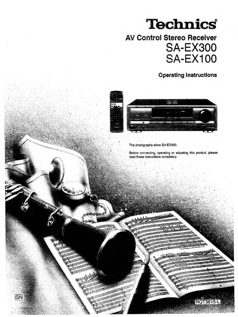
Technics SA-EX100 User manual

Dear
Customer
Thank
you
for
purchasing
this
Technics
product.
For
optimum
performance
and
safety,
please
read
these
instructions
carefully.
These
operating
instructions
are
applicable
to
models
SA-EX300
and
SA-EX100.
These
operating
instructions,
however,
are
intended
primarily
for
model
SA-EX300.
THIS
TUNER/RECEIVER
IS
CAPABLE
OF
RECEIVING
THE
NEW
AM
STEREO
BROADCASTS
FROM
THE
AM
BAND
RADIO
STATIONS.
HOWEVER
LIKE
MANY
TUNERS
AND
RECEIVERS
CURRENTLY
AVAILABLE
ON
THE
MARKET
IT
WILL
REPRODUCE
THIS
AM
STEREO
SIGNAL
ONLY
IN
AM
MONO,
WHICH,
IN
EFFECT,
iS
OF
NO
LESSER
QUALITY
THAN
YOUR
EXISTING
AM
MONO
TUNER/RECEIVER.
Table
of
contents
Accessories.2
Suggestions
for
safety.3
Front
panel
controls.4
Equipment
connections.5
Antenna
connections.8
Speaker
connections.
10
Basic
operations.12
To
adjust
the
tone
quality.13
To
adjust
the
sound
balance.13
To
mute
the
sound
level.13
To
listen
through
headphones.13
Listening
to
radio
broadcasts.14
Sequential
tuning.14
Preset
tuning.14
Direct
access
tuning.16
Enjoying
sound
with
DOLBY
PRO
LOGIC
SA-EX300
onl'
SURROUND.
1
7
3
STEREO.17
Setting
the
center
mode.17
Adjusting
speaker
output
level.18
Enjoying
with
SURROUND
or
3
STEREO.19
Making
a
recording.20
Recording
on
the
tape
deck.20
Recording
on
the
VCR
(VCR
1).20
Sleep
timer
function.22
SA-EX300
onl
Troubleshooting
guide.23
Technical
specifications.Back
cover
Please
check
and
identify
the
supplied
acces¬
sories
|
|
AC
power
supply
cord.1
pc.
j
~~|
AM
loop
antenna
set
•
AM
loop
antenna.1
pc.
•
AM
loop
antenna
holder.1
pc.
•
Screw.1
pc.
□
FM
indoor
antenna.
1
pc.
f~j
Remote
control
transmitter
For
SA-EX300
!
(RAK-SA612WH)
!
.1
pc.
For
SA-EX100
(EUR642175)
Q
Batteries
(UM-4,
“AAA",
R03).2
pcs.
®ZZD
6
)
)
For
details
on
remote
control
transmitter
operation,
refer
to
“How
to
use
the
remote
control
transmitter"
in
the
separate
booklet.
Placement
Foreign
materials
Avoid
placing
the
unit
in
areas
of:
•
direct
sunlight
•
high
temperature
•
high
humidity
•
excessive
vibration
•
uneven
surfaces
(Place
the
unit
on
a
flat
level
surface.)
Such
conditions
might
damage
the
cabinet
and/or
other
component
parts
and
thereby
shorten
the
unit's
service
life.
Ventilation
•
Place
the
unit
in
a
well
ventilated
position
at
least
10
cms
away
from
wall
surfaces
etc.
•
Ensure
that
curtains
and
similar
materials
do
not
obstruct
the
ven¬
tilation
holes.
Stacking
Never
place
heavy
items
on
top
of
the
unit
or
the
power
cord.
Voltage
•
It
is
very
dangerous
to
use
an
AC
power
source
of
high
voltage
such
as
for
an
air
conditioner.
A
fire
might
be
caused
by
such
a
connection.
■
A
PC
power
source
can
not
be
used.
Be
sure
to
check
the
power
source
carefully,
especially
on
a
ship
or
other
place
where
DC
is
used.
Power
cord
protection
•
Avoid
cuts,
scratches
or
poor
connection
of
the
AC
mains
cord,
as
this
may
result
in
fire
or
electric
shock
hazard.
Excessive
bending,
putting
or
slicing
of
the
cord
should
also
be
avoided.
•
Do
not
pull
on
the
cord
when
you
are
disconnecting
the
power,
as
this
could
cause
an
electric
shock.
Grasp
the
plug
firmly
when
you
disconnect
the
power
supply.
•
Never
touch
the
plug
with
wet
hands
or
a
serious
electric
shock
could
result.
•
Ensure
that
no
foreign
objects,
such
as
needles,
coins,
screw¬
drivers
etc.,
accidentally
fall
into
the
unit
or
through
the
ventilation
holes.
Otherwise,
a
serious
electric
shock
or
malfunction
could
occur.
•
Be
extremely
careful
about
spilling
water
or
liquid
on/into
the
unit,
as
a
fire
or
electric
shock
could
occur.
(Disconnect
the
power
plug
and
contact
your
dealer
immediately
if
this
occurs.)
•
Avoid
spraying
insecticides
onto
the
unit
as
they
contain
flamma¬
ble
gases
which
can
be
ignited.
•
Insecticides,
aicohoi,
paint
thinner
and
similar
chemicals
should
never
be
used
to
clean
the
unit
as
they
can
cause
flaking
or
cloudiness
to
the
cabinet
finish.
Maintenance
Clean
the
cabinet,
panel
and
controls
with
a
soft
cloth
lightly
moist¬
ened
with
mild
detergent
solution.
Do
not
use
any
type
of
abrasive
pad,
scouring
powder
or
solvent
such
as
alcohol
or
benzine.
Service
•
Never
attempt
to
repair,
disassemble
or
reconstruct
the
unit
if
there
seems
to
be
a
problem.
A
serious
electric
shock
could
result
if
you
ignore
this
precaution¬
ary
measure.
•
If
a
problem
occurs
during
operation
(the
sound
is
interrupted,
indicators
fail
to
illuminate,
smoke
is
detected,
etc)
contact
your
dealer
or
Authorized
Service
Center
immediately.
•
Disconnect
the
power
supply
if
the
unit
will
not
be
used
for
a
long
time.
Otherwise
the
operation
fife
could
be
shortened.
CAUTION
Do
not
place
a
tape
deck
or
CD
player
on
top
of
this
unit.
Heat
radiated
from
the
top
of
this
unit
may
cause
damage
to
the
tape
or
CD
software.
CAUTION!
DO
NOT
INSTALL
OR
PLACE
THIS
UNIT
IN
A
BOOKCASE,
BUILT
IN
CABINET
OR
IN
ANOTHER
CONFINED
SPACE
IN
ORDER
TO
KEEP
WELL
VENTILATED
CONDITION.
ENSURE
THAT
CURTAINS
AND
ANY
OTHER
MATERIALS
DO
NOT
OBSTRUCT
THE
VENTI¬
LATION
CONDITION
TO
PREVENT
RISK
OF
ELECTRIC
SHOCK
OR
FIRE
HAZARD
DUE
TO
OVERHEATING.
No.
_
Name
_
Ref,
page
©
Power
“STANDBY
0
/ON”
switch
12
(POWER,
STANDBY
O/ON)
Press
to
switch
the
unit
from
on
to
standby
mode
or
vice
versa,
in
standby
mode,
the
unit
is
still
consuming
a
small
amount
of
power.
©
Tuning
buttons
(TUNING)
14
©
Band
select
button
(BAND)
14
0
FM
mode
select
button
(FM
AUTO/MONO)
14
©
Memory
button
(MEMORY)
15
©
Preset
channel
buttons
(PRESET)
15,16
©
Remote
control
signal
sensor
(SENSOR)
©
“STANDBY"
indicator
(STANDBY)
When
the
unit
is
connected
to
the
AC
mains
supply,
this
indica¬
tor
lights
up
in
standby
mode
and
goes
out
when
the
unit
is
turned
on.
®Bnn
Surround
button
(SURROUND)
17,18,19
3
stereo
button
(3
STEREO)
17,18,19
No.
Name
Ref.
page
Center
mode
select
button
(CENTER
MODE)
17
©
Display
-
©
Muting
button
(MUTING)
13
©
Volume
control
(VOLUME)
12
©
Headphones
jack
(PHONES)
13
©
Speaker
button
(SPEAKERS)
12
Sleep
timer
button
(SLEEP)
22
©
Input
select
buttons
12
©
Tape
monitor
button
(TAPE
MONITOR)
12,20
©
Bass
control
(BASS)
13
©
Treble
control
(TREBLE)
13
©
Balance
control
(BALANCE)
13
Make
sure
that
the
power
supply
for
all
components
has
been
turned
off
before
making
any
connections.
Stereo
connection
cable
=o>®»\
_
^mnr~h
(L)
White
(not
included)
(R)
Red
Ai
to
raa
Do
not
place
books,
etc.,
on
top
of
this
unit
or
block
the
heat
radiation
vents
in
any
way
SA-EX300
Make
sure
that
the
power
supply
for
all
components
has
been
turned
off
before
making
any
connections.
OUTPUT
|
I
GND
Only
for
turntable
—-
with
ground
terminal
Cooling
fan
The
cooling
fan
operates
at
high
power
output
levels
only.
PHONO
CD
TA
REC
(OUT)
PE
PLAY
(IN)
VCR
OUT
IN
®
©
o
o
o
0
oo
AC
power
supply
cord
^
(included)
Connect
this
cord
after
ail
other
cables
and
cords
are
connected.
Household
AC
outlet
AUDIO
IN
VCR
(not
included)
AUDIO
OUT
VIDEO
=T=f1
OUT
Video
connection
cable
(not
included)
TV
(not
included)
r
SA-EX300
onl
To
connect
a
TV
and
VCR
with
21
pin
scart
terminal
TV
(not
included)
To
connect
a
second
VCR
SA-EX300
onl
9
FM
indoor
antenna
(included)
This
antenna
is
normally
sufficient
for
reception
of
FM
broadcasts.
FM
indoor
antenna
(included)
Attach
to
a
wall
(using
a
tack
or
tape)
facing
in
the
direction
of
best
reception.
For
best
reception
sound
quality
An
FM
outdoor
antenna
is
recommended.
Disconnect
the
antenna
if
an
FM
outdoor
antenna
is
installed.
FM
outdoor
antenna
(not
included)
The
outdoor
antenna
should
be
used
when
using
the
main
unit
in
mountainous
areas
or
in
spaces
enclosed
by
reinforced
concrete
where
the
FM
indoor
antenna
(included)
does
not
provide
satisfac¬
tory
reception.
An
outdoor
antenna
should
be
installed
by
a
qualified
technician
only.
FM
outdoor
antenna
(not
included)
■
How
to
use
the
antenna
plug
(included)
Two
types
of
wire
are
most
commonly
used
for
connection
from
the
antenna:
300-ohms
parallel
feeder
wire
or
75-ohms
coaxial
cable.
For
best
resistance
to
outside
interference,
the
use
of
75-ohms
coaxial
cable
is
suggested.
-
To
connect
a
75-ohms
coaxial
cable
©
Remove
a
piece
of
the
outer
vinyl
insulator.
c
20
mm
10mm
(
2
)
Remove
the
cover
while
pulling
the
tabs.
If
the
tabs
are
pulled
too
hard,
the
casing
may
be
damaged.
©
Remove
the
lead
wire
and
clamp
it
with
the
plastic
bar.
.Lead
wire
Plastic
bar
®
Install
the
coaxial
cable.
Press
down
with
pliers.
(D
Attach
the
cover.
Clamp
the
cable
con¬
ductor,
and
wind
it
on
so
that
it
doesn’t
contact
anything
else.
AM
loop
antenna
(included)
AM
outdoor
antenna
(not
included)
This
antenna
is
normally
sufficient
for
reception
of
AM
broadcasts.
install
the
AM
loop
antenna
holder
(included)
at
the
rear
panel
of
this
unit
and
then
attach
the
AM
loop
antenna
to
the
AM
loop
anten¬
na
holder
(facing
in
the
direction
of
best
reception).
When
mounting
the
antenna
to
a
column,
a
wall
or
rack
Mount
it
vertically.
The
outdoor
antenna
should
be
used
when
using
the
main
unit
in
mountainous
areas
or
in
spaces
enclosed
by
reinforced
concrete
where
the
AM
loop
antenna
(included)
does
not
provide
satisfactory
reception.
Stretch
5-12
m
of
vinyl-covered
wire
horizontally
across
a
window
frame
or
other
convenient
location,
keeping
it
as
high
as
possible
from
the
ground.
When
the
unit
is
not
in
use,
disconnect
the
outdoor
antenna
to
pre¬
vent
possible
damage
that
may
be
caused
by
lightning.
Never
use
an
outdoor
antenna
during
an
electrical
storm.
WORM
Be
sure
to
connect
the
AM
loop
antenna
even
when
an
AM
outdoor
antenna
is
used.
Pay
attention
to
the
following
points
when
mounting
the
antenna.
•
Do
not
mount
it
horizontally
(doing
so
will
impair
reception).
•
Do
not
mount
it
close
to
power
supply
cords,
speaker
wires
or
metal
surfaces
(doing
so
will
result
in
noise).
•
Do
not
mount
it
close
to
a
tape
deck.
When
the
tape
deck
is
being
used,
chirping
or
beeping
sounds
may
result.
olby
Pro
Logic
Systems
Connection
of
front
speakers
As
well
as
enjoying
normal
stereo
reproduction
with
the
left
and
right
front
speakers,
a
center
speaker
and
surround
speakers
can
also
be
connected
to
this
unit
in
order
to
enjoy
the
sound
perfor¬
mance
of
Dolby
Pro
Logic
Systems.
The
illustration
below
shows
where
to
place
the
speakers
so
as
to
best
enjoy
sound
with
Dolby
Pro
Logic
systems.
We
recommend
that
surround
speakers
be
placed
on
the
side
of
or
slightly
behind
the
listener,
and
about
one
meter
higher
than
ear
level.
However
the
position
should
be
adjusted
to
your
personal
prefer¬
ence,
because
the
effect
varies
to
some
degree
depending
upon
the
sources.
Surround
speaker
Surround
speaker
(not
included)
(not
included)
(Left)
(Right)
The
subwoofer
can
be
placed
in
any
position.
■
Speaker
Impedance
The
impedance
of
any
speaker
used
with
this
unit
must
be
8-16
£2.
Connection
of
surround
speakers
MifsMclililifflM
Connection
of
subwoofer
WMMm
1
Right
speaker
Leftspeaker
annum
1.
Before
sound
can
be
heard,
both
surround
speakers
must
be
connected.
2.
Do
not
connect
the
surround
speakers
to
the
front
speaker
ter¬
minals.
The
surround
speakers
may
be
damaged
if
connected
to
the
front
terminals
due
to
the
output
power
difference
between
the
front
and
surround
terminals.
■
Speaker
impedance
The
impedance
of
any
speaker
used
with
this
unit
must
be
4-16
£1.
Connection
of
center
speaker
EUMJEag
You
can
amplify
bass
sounds
by
connecting
a
subwoofer
to
your
receiver.
When
connected,
the
subwoofer
can
be
placed
in
any
position.
This
receiver
has
no
amplifier
section
designed
especially
for
the
subwoofer,
so
you
cannot
adjust
the
subwoofer
volume
level
by
the
receiver.
Connecting
a
subwoofer
which
does
not
have
a
built-in
amplifier
Connect
an
optional
amplifier
to
the
“SUBWOOFER”
terminals
of
this
unit
and
then
connect
a
subwoofer
to
the
speaker
terminals
of
the
amplifier.
Before
sound
can
be
heard,
the
SURROUND
mode
or
3
STEREO
mode
(of
the
Dolby
Pro
Logic
system)
must
be
on.
■
Speaker
impedance
The
impedance
of
any
speaker
used
with
this
unit
must
be
8-16
Cl.
11
Before
operation,
set
VOLUME
to
the
“MIN"
position.
W
“
Press
POWER
to
switch
on
the
power.
SPEAKERS
Press
SPEAKERS
and
check
the
“SPEAKERS”
indication
lights
up.
Lights
up
If
the
button
is
pressed
once
more,
the
indicator
will
switch
off
and
no
sound
wilt
be
heard
from
the
speakers.
Press
to
select
the
desired
source.
/“
T)
i
_
U
Example
shows
CD
is
selected
as
the
source.
b
To
watch
a
video
or
the
TV,
set
the
TV
to
either
the
TV
mode
or
VIDEO
mode
as
indicated
below.
•
To
enjoy
videos
(VCR
1
or
VCR
2)
Set
it
to
VIDEO
mode.
•
To
watch
TV
Set
it
to
TV
mode.
For
SA-EX100
VCR:
To
listen
to
vi
deo
tapes
[TAPE
MO
NITOR
I:To
listen
to
cassette
tapes
(The
tape
monitor
indicator
will
appear.)
(See
below.)
CD:
To
listen
to
compact
discs
TUNER:
To
listen
to
radio
broadcasts
PHONO:
To
listen
to
phono
discs
Start
the
desired
source.
(Refer
to
the
appropriate
operating
instructions
for
details.)
Turn
VOLUME
to
adjust
the
volume
level.
After
listening
is
finished
Be
sure
to
reduce
the
volume
level,
and
switch
the
power
to
the
standby
condition
by
pressing
POWER.
For
SA-fcrX300
VCR
1:
To
watch
video
tapes
(VCR
1)
TV/VCR
2:
To
watc
h
TV
or
video
tapes
(VCR
2)
I
TAPE
MONITOR
I
:
To
listen
to
cassette
tapes
(The
tape
monitor
indicator
will
appear.)
(See
right.)
CD:
To
listen
to
compact
discs
TUNER:
To
listen
to
radio
broadcasts
PHONO:
To
listen
to
phono
discs
When
the
tape
monitor
indicator
Is
lit
or
flashing
This
indicates
that
the
tape
monitor
function
of
this
unit
is
ON.
To
listen
to
sou
r
ces
other
than
a
tape,
be
sure
to
press
1
TAPE
MONITOR
I
and
check
the
indicator
goes
out.
Lit
or
flashing
|
TAPE
MQNITOhI
12
MUTING
To
adjust
the
tone
quality
€
MIN
MAX
Turn
BASS
to
adjust
the
low
frequency
sound.
„
.
treble
MIN
MAX
Turn
TREBLE
to
adjust
the
high
frequency
sound.
To
adjust
the
sound
balance
,
BALANCE
Turn
BALANCE
to
adjust
the
O'
L
R
left/right
sound
balance.
To
mute
the
sound
level
MUTING
Press
MUTING.
n/tt
i
T
T
n
n
i~l
i
n_i
t
j_
i
i//_7
i_i
The
message
“MUTING
ON
NOW”
runs
repeatedly
from
right
to
left
across
the
display
as
long
as
the
muting
function
is
on.
Press
once
again
to
return
to
the
previ¬
ous
volume
level.
To
listen
through
headphones
Use
VOLUME
to
reduce
the
volume
level,
and
con¬
nect
the
headphones.
if
you
do
not
want
sound
from
the
speakers,
press
SPEAKERS
and
check
the
“SPEAKERS”
indication
goes
out.
SA-EX300
on!
If
a
subwoofer
is
connected
to
your
system,
turn
off
power
to
it
or
the
subwoofer
amp
you
are
using.
WMsin
a
Avoid
listening
for
prolonged
periods
of
time
to
prevent
hearing
damage.
13
Sequential
tuning
You
can
use
the
tuning
buttons
to
tune-in
radio
broadcasts.
FM
AUTO/MONO
2
3
1
Press
TUNER.
Press
BAND
to
select
“FM”
or
“AM”.
/_
n/i
ii
i
Selected
band
v
TUNING
A
Press
V
or
A
to
tune
to
the
desired
broadcast.
If
either
button
is
held
down
for
an
instant
until
the
frequency
begins
to
scroll,
the
broadcast
stations
can
be
tuned
in
automatically
when
a
broadcast
station
is
found.
Tuning
may
stop
automatically
if
any
jamming
is
encountered.
Lights
up
when
tuned
Lights
up
when
an
FM
stereo
broadcast
is
received
QUARTZ
LOCK
STEREO
nn
I
I
IIQ
n
/
QQ
//_/
itH*
Frequency
display
If
noise
Is
excessive
in
the
FM
stereo
mode
Press
FM
AUTO/MONO.
(The
"STEREO"
indication
will
switch
off.)
QUARTZ
LOCK
MONO
inn
iii
a
a
I
III,
lL_l
MHz
Lights
up
The
broadcast
will
be
monaural,
but
noise
will
be
reduced.
If
the
button
is
pressed
once
more,
the
stereo
mode
will
be
resumed.
Preset
tuning
Presetting
radio
stations
into
the
memory
channels
of
this
unit
makes
selecting
stations
easy
and
simple.
AJc/w
e
pt
tr&er
mug
How
many
broadcast
stations
can
be
preset?
A
total
of
30
FM
and
AM
stations
can
be
preset.
How
Is
presetting
done?
The
two
following
methods
are
available.
0
Automatic
memory
presetting
Automatic
memory
presetting
allows
this
unit
to
automatically
search
for
broadcast
stations
and
then
preset
them
into
memory.
With
this
function,
searching
proceeds
from
the
frequency
currently
being
displayed
and
continues
through
higher
fre¬
quencies,
and
broadcast
stations
are
preset
in
the
order
in
which
they
are
located.
With
this
method,
the
channels
that
can
be
preset
into
the
memory
are
set
as
follows
for
different
bands
(FM
or
AM).
Channel
If
the
FM
stations
(channels
1-30)
are
preset
and
then
the
AM
stations
(channels
21-30)
are
preset
Because
this
unit
can
accommodate
a
total
of
30
preset
channels,
the
settings
for
FM
channels
21-30
will
be
replaced
by
the
AM
settings
which
were
subsequently
pre¬
set,
and
the
channel
allotment
will
be
as
shown
below.
Channel
For
FM
broadcast
stations.1-20
For
AM
broadcast
stations.21-30
d)
Manual
memory
presetting
The
desired
broadcast
stations
can
be
preset
into
the
desired
channels
by
the
user.
This
can
also
be
used
as
a
method
for
changing
selected
broadcast
stations
that
were
preset
in
“Automatic
memory
presetting”.
Please
remember
this
If
a
new
broadcast
station
is
preset
into
a
channel,
the
setting
for
the
broadcast
station
which
was
previously
entered
in
that
chan¬
nel
will
be
automatically
erased.
Automatic
memory
presetting
2
Manual
memory
presetting
2
3
4
Set
to
the
frequency
from
which
you
want
to
start
auto¬
matic
memory
presetting.
(See
page
14.)
MEMORY
-MANUAL-AUTO
Press
MEMORY
until
the
fre¬
quency
begins
to
change.
(Automatic
memory
presetting
will
start.)
During
automatic
memory
presetting,
the
memory
indicator
will
flash
while
the
frequency
scrolls.
/
a
(
r.S
Flas
hes
To
stop,
press
MEMORY
once
again.
When
a
broadcast
station
is
preset
The
memory
indicator
and
the
preset
channel
number
will
be
dis¬
played
for
approximately
1
second.
—
□
_
t
~
it
i
—
L.
ii
l
Lights
up
When
presetting
is
completed
The
last
broadcast
station
to
be
preset
will
be
displayed.
Frequencies
may
not
be
preset
correctly
in
cases
where
the
broad¬
cast
waves
are
too
strong
or
too
weak,
in
such
cases,
carry
out
presetting
manually.
Set
to
the
desired
broadcast.
(See
page
14.)
If
interference
or
static
is
keeping
you
from
enjoying
an
FM
broadcast,
press
FM
AUTO/MONO
and
change
to
monaurual.
You
can
preset
the
memory
in
monaurual
just
as
in
stereo,
Press
MEMORY.
(Touch
only.)
Lights
up
To
cancel
the
memory
function,
press
MEMORY
again.
Press
V
or
A
to
select
the
desired
channel.
i
i
Flashes
Holding
the
buttons
down
lets
you
scroll
through
channels
faster.
Press
MEMORY.
\
\
/
i
'I
i—
n
i
The
channel
will
blink
on
the
display.
QUARTZ
LOCK
STEREO
On
n
/
/
/
n~~i
III
MHl
To
continue
presetting
Repeat
steps
1
through
4.
Preset
tuning
(continued)
To
listen
to
preset
broadcast
stations
i
v
PRESET
/S
Press
V
or
A
to
select
the
desired
channel.
■
i
t_/
/
2
Preset
channel
Holding
the
buttons
down
lets
you
scroll
through
channels
faster.
After
the
preset
channel
is
displayed,
the
frequency
of
the
selected
channel
is
displayed.
You
can
select
channels
from
the
remote
control
with
the
numeric
buttons.
See
the
instruction
manual
on
“How
to
use
the
remote
control
transmitter”.
To
confirm
the
channel
number
of
the
broadcast
station
being
received
Press
TUNER.
(The
channel
number
will
be
displayed
for
approximately
1
second.)
Wt
Vtft/a
The
channel
number
is
not
displayed
if
you
change
the
reception
frequency
or
FM
mode
setting.
For
your
reference
Even
if
the
power
is
switched
to
standby
or
the
power
cord
is
dis¬
connected
from
the
household
AC
outlet,
the
memory
will
retain
its
contents
for
approximately
one
month.
If
frequency
presettings
are
accidentally
erased
Make
the
presettings
once
again.
The
power
cord
should
remain
connected
for
one
hour
or
more
for
the
memory
back-up
to
be
effective.
Direct
access
tuning
(Only
available
from
the
remote
control.)
Specify
the
frequency
using
the
numeric
buttons
on
the
remote
con¬
trol
transmitter
to
directly
tune
to
the
desired
broadcast
station.
First
select
the
band
with
the
BAND
button
on
the
receiver.
S
A-EX100
Press
TUNER.
This
will
set
the
remote
control
to
oper¬
ate
the
tuner.
Press
DIRECT
TUNING,
V
Flashes
While
cursor
display
is
flashing
(approx.
10
seconds)
Press
the
appropriate
numeric
buttons
to
enter
the
frequen¬
cy.
if
the
desired
FM
frequency
is
107.90
MHz
/_
i\/i
/
/
/
/—/
-ion
1LJ
IS
/_/
MHx
If
the
frequency
has
been
input
correctly,
the
displayed
frequency
will
blink
once.
1.
If
no
button
is
pressed
while
the
cursor
display
is
flashing,
the
display
will
return
to
the
frequency
which
is
currently
being
received.
To
re-specify
the
frequency,
repeat
the
procedure
from
step
2.
2.
If
the
frequency
has
not
been
input
correctly,
“ERROR*
indica¬
tion
will
be
displayed.
In
this
case,
re-enter
the
frequency.
By
combining
front,
center
and
surround
speakers,
you
can
enjoy
the
SURROUND
mode
which
conveys
a
feeling
of
presence
or
the
3
STEREO
mode
which
conveys
a
feeling
of
orientation.
SURROUND
By
reproducing
the
feeling
of
depth
and
movement
of
sound,
video
software
or
compact
discs
recorded
with
Dolby
Surround
provide
the
listener
with
a
feeling
of
presence
like
that
of
a
movie
theater.
To
enjoy
SURROUND,
be
sure
to
connect
the
surround
speakers.
3
STEREO
You
can
enjoy
audio/video
sources
with
clear
sound,
more
pres¬
ence
and
a
good
feeling
of
orientation.
3
STEREO
can
be
used
with
non
DOLBY
SURROUND
recordings.
To
enjoy
3
STEREO,
be
sure
to
connect
the
center
speaker.
Manufactured
under
license
from
Dolby
Laboratories
Licensing
Corporation.
“Dolby",
the
doubie-D
symbol
□□
and
“Pro
Logic”
are
trademarks
of
Dolby
Laboratories
Licensing
Corporation.
Setting
the
center
mode
For
Dolby
Pro
Logic
systems,
center
mode
setting
is
necessary
to
play
back
bass
sounds
effectively.
Set
the
center
mode
in
accordance
with
the
size
of
your
center
speaker.
1
2
Press
SURROUND
or
3
STEREO
to
turn
on
the
desired
mode.
Pressing
the
same
button
again
turns
off
the
activated
listening
mode.
3STEREQ
For
SURROUND
mode
iTlfldiavauflHliai
*
*
o
.
l
o
a
i
c
/
/
nil
ii
ii
i
n
i
Ti
^T
/T
I__II_II
i
tjj
|
Displayed
for
approximately
1
second
only.
For
3
STEREO
mode
\
-i
or
c
n
c
-i
003
8TEReo
)
|
3
'
1
i-
'»
i__
i_i
,
_
I
Displayed
for
approximately
1
second
only.
Press
CENTER
MODE
to
select
the
correct
center
mode.
When
the
button
is
pressed,
the
current
center
mode
is
displayed.
Pressing
it
again
changes
the
center
mode.
NORMAL
When
the
center
speaker
is
smaller
than
the
front
speakers
WIDEBAND
When
the
center
speaker
is
the
same
or
larger
size
as
the
front
speakers
PHANTOM
SURROUND
onl
i
When
no
center
speaker
is
connected.
in
the
PHANTOM
mode,
the
sound
which
would
have
been
sent
to
the
center
speaker
witi
be
divided
equally
between
both
the
left
and
right
front
speakers.
Adjusting
SpCttkCT*
output
level
(Only
available
from
the
remote
control.)
In
order
to
reproduce
the
movement
of
the
sound
and
its
clear
ori¬
entation,
it
is
important
to
adjust
the
output
level
of
each
speaker.
Adjust
output
to
the
correct
levels
while
listening
to
the
test
signal.
irana
•
When
ready
to
adjust
speaker
output
level,
situate
yourself
away
from
the
speakers
as
you
normally
do
when
listening.
•
First
turn
ON
the
speakers
with
the
SPEAKERS
button
on
the
receiver.
•
If
front
speakers
volume
is
unbalanced,
adjust
the
balance
with
the
BALANCE
knob.
Press
TEST
to
output
a
test
signal.
T
CO
T
i
i~
~i
i
/
L.
T
The
speaker
outputting
the
test
signal
is
displayed
while
the
test
is
running.
L:
Front
speaker
(left)
C:
Center
speaker
R
:
Front
speaker
(right)
S:
Surround
speakers
For
surround
mode
L
—
C
—*•
R
S
In
the
PHANTOM
mode,
the
center
speaker
is
OFF,
so
the
test
signal
is
not
output
and
“C”
is
not
displayed.
For
3
STEREO
mode
L
-
►
C
—
R
t_i
](=
i
Press
VOLUME
(-)
or
(+)
to
set
J
the
volume
level
normally
used
for
enjoying
the
source.
Press
□□
PRO
LOGIC
to
turn
on
the
Dolby
Pro
Logic
sys¬
tems
and
select
the
desired
mode.
For
SURROUND
mode
/_
/
iiii~u~)i
i
n
t
Ti
Q
/_/
/T
/T
/
1
/
jj
|
P
R
0
•
L
0
Q
I
C
Displayed
for
approximately
f
second
only.
For
3
STEREO
mode
—)
i
—
y
j
—
/—}
j—
/—j
DO
3
STEREO
-I
I
Qi~r
I~I-I
|_
The
following
steps
are
for
setting
the
output
level
of
the
front
speakers
and
the
center/surround
speakers
to
the
same
listening
level.
Press
CH
SELECT
to
select
the
speaker
you
want
to
adjust.
For
the
center
speaker
For
the
surround
speakers
C
i
V
O
ii
CD
JJ
Displayed
for
approximately
1
second
only.
Enjoying
with
SURROUND
or
3
STEREO
-C
HLEVE
L
+
CD
O
Press
CH
LEVEL
(-)
or
(+)
to
adjust
the
output
level.
-:
Decrease
the
output
level.
+
:
Increase
the
output
level.
/
J.
QV
_/
±>
T
Output
level
can
be
varied
within
a
range
of
-12
dB
to
+12
dB
with
front
speaker
output
level
serving
as
the
zero
point.
Repeat
steps
4
and
5
until
the
output
level
of
all
speakers
is
the
same.
WBT7SB
1.
The
test
signal
is
output
only
by
the
speaker
you
are
now
adjusting
and
does
not
repeat
the
sequence
until
adjustments
are
complete.
2.
Remember
you
cannot
adjust
output
level
of
the
surround
speakers
if
you
selected
the
3
stereo
mode
in
step
1.
To
stop
the
test
signal
^
Press
TEST.
To
turn
off
the
Dolby
Pro
Logic
systems
SURROUND
Press
the
button
of
the
currently
selected
mode
(SURROUND
or
3
STEREO).
3
1
|
~~
|
Select
the
desired
source.
Start
the
desired
source.
When
employing
SURROUND,
use
soft¬
ware
recorded
in
Dolby
Surround.
Press
SURROUND
or
3
STEREO
to
turn
on
the
desired
mode.
Pressing
the
same
button
again
turns
off
the
activated
listening
mode.
Recording
on
the
tape
deck
Before
recording,
prepare
the
tape
deck
for
recording
{recording
level
adjustment,
etc.).
See
the
tape
deck's
operating
instructions
for
details.
Recording
on
the
VCR
(VCR
1)
Before
recording,
prepare
the
VCR
(VCR1)
for
recording
(recording
level
adjustment,
input
selector
setting,
etc.).
See
the
VCR’s
operating
instructions
for
details.
Recording
from
an
audio
source
J
r
-^
I
_
=====
—
H
0
O
0
b
pHH
11
mi
1
[—
'gr
-ua.-1
m\^
•
-
i
DDD
Select
the
desired
source
to
be
recorded.
Press
any
button
except
TAPE
MONI¬
TOR
to
select
the
source
you
want
to
record
from.
Begin
recording.
Follow
your
tape
deck’s
operating
instructions.
Begin
the
desired
source
to
be
recorded.
Select
the
audio
source
to
be
recorded.
Press
either
CD,
TUNER
or
PHONO
to
select
the
source
you
want
to
record
from.
Recording
from
the
tape
deck
is
not
possible.
Begin
recording
on
the
VCR
1
.
Follow
your
VCR’s
operating
instruc¬
tions.
Begin
the
audio
source
to
be
recorded.
To
check
the
sound
recorded
while
a
recording
is
being
made
With
a
tape
deck
with
3
head
system,
it
is
possible
to
check
the
sound
recorded
on
the
tape.
Press
1
TAPE
MONITOR
1
on
this
unit
and
set
the
monitor
button
on
the
tape
deck
to
“TAPE".
Lit
|t*pb
monitor!
Press
I
TAPE
MONITOR
I
once
again
to
turn
it
off.

Other manuals for SA-EX100

3

This manual suits for next models

1

Other Technics Stereo Receiver manuals
Technics SAEX140 - RECEIVER User manual

Technics

Technics SAEX140 - RECEIVER User manual

Technics SA-222 User manual

Technics

Technics SA-222 User manual

Technics SA-GX350 User manual

Technics

Technics SA-GX350 User manual

Technics SA-AX910 User manual

Technics

Technics SA-AX910 User manual

Technics SA-203 User manual

Technics

Technics SA-203 User manual

Technics SA-DA10 User manual

Technics

Technics SA-DA10 User manual

Technics SAEX110 - RECEIVER User manual

Technics

Technics SAEX110 - RECEIVER User manual

Technics SA-EX120 User manual

Technics

Technics SA-EX120 User manual

Technics SA-GX910 User manual

Technics

Technics SA-GX910 User manual

Technics SAAX6 - RECEIVER User manual

Technics

Technics SAAX6 - RECEIVER User manual

Technics SA-GX530 User manual

Technics

Technics SA-GX530 User manual

Technics SA-GX550 User manual

Technics

Technics SA-GX550 User manual

Technics SA-EX510; SA-EX410; SA-EX310 User manual

Technics

Technics SA-EX510; SA-EX410; SA-EX310 User manual

Technics SAAX6 - RECEIVER User manual

Technics

Technics SAAX6 - RECEIVER User manual

Technics SA-AX540 User manual

Technics

Technics SA-AX540 User manual

Technics SA-AX540 User manual

Technics

Technics SA-AX540 User manual

Technics SA-GX505 User manual

Technics

Technics SA-GX505 User manual

Technics SA-110 User manual

Technics

Technics SA-110 User manual

Technics RQT5110-P User manual

Technics

Technics RQT5110-P User manual

Technics SA-GX170 User manual

Technics

Technics SA-GX170 User manual

Technics SA-DX940 User manual

Technics

Technics SA-DX940 User manual

Technics SA-5570 User manual

Technics

Technics SA-5570 User manual

Technics SA-EX120 User manual

Technics

Technics SA-EX120 User manual

Technics SA-GX670 User manual

Technics

Technics SA-GX670 User manual
Popular Stereo Receiver manuals by other brands

Magnadyne LS4000B Linear Series owner's manual

Magnadyne

Magnadyne LS4000B Linear Series owner's manual

Pioneer SX-2900 operating instructions

Pioneer

Pioneer SX-2900 operating instructions

DEGEN DE106 operating manual

DEGEN

DEGEN DE106 operating manual

Sony STR-DA9000ES - Fm Stereo/fm-am Receiver Service manual

Sony

Sony STR-DA9000ES - Fm Stereo/fm-am Receiver Service manual

Sony STR-V444ES - Fm Stereo/fm-am Receiver operating instructions

Sony

Sony STR-V444ES - Fm Stereo/fm-am Receiver operating instructions

Onkyo TX-8050 instruction manual

Onkyo

Onkyo TX-8050 instruction manual

Sony STR-GX5ES Service manual

Sony

Sony STR-GX5ES Service manual

Sony STR-DE305 Service manual

Sony

Sony STR-DE305 Service manual

NAD T737 owner's manual

NAD

NAD T737 owner's manual

NAD T785 Specification sheet

NAD

NAD T785 Specification sheet

Marantz ZR6001 user guide

Marantz

Marantz ZR6001 user guide

Pyle PLMR15BW user manual

Pyle

Pyle PLMR15BW user manual

Teac AG-790 Service manual

Teac

Teac AG-790 Service manual

Williams Sound SoundPlus Value Courtroom System WIR SYS 2 Specification sheet

Williams Sound

Williams Sound SoundPlus Value Courtroom System WIR SYS 2 Specification sheet

Sony STR-DE997 - Fm Stereo/fm-am Receiver operating instructions

Sony

Sony STR-DE997 - Fm Stereo/fm-am Receiver operating instructions

Aiwa AV-DV95 operating instructions

Aiwa

Aiwa AV-DV95 operating instructions

Sony XAV-AX8500 operating instructions

Sony

Sony XAV-AX8500 operating instructions

Sansui 890 Service manual

Sansui

Sansui 890 Service manual

manuals.online logo
manuals.online logoBrands
  • About & Mission
  • Contact us
  • Privacy Policy
  • Terms and Conditions

Copyright 2025 Manuals.Online. All Rights Reserved.