Technik-Plus FRONT-TURBO User manual

1
*Translation
from original*
TECHNIK-PLUS Sämaschinen e.U.
Industrieparkstrasse 6-8
A-8480 Mureck
www.technik-plus.eu
Tel: + 43 3472 21 120
Serial no.:
Instruction
for seeder
“FRONT-TURBO”
Version 08/2020

2
Content
SAFETY ......................................................................................................................................................................... 3-6
MOUNTING ................................................................................................................................................................. 6-9
CHANGING OF SEED ROLL ............................................................................................................................................ 10
BOTTOM FLAP, COVER SHEET ...................................................................................................................................... 11
HYDRAULIC-SYSTEM .................................................................................................................................................... 12
HOW TO STORE CABLES CORRECT ............................................................................................................................... 12
PROFICONTROL UNIT .............................................................................................................................................. 13-15
SEEDER+ / TWIN UNIT ............................................................................................................................................. 16-19
CHECKING POINTS ........................................................................................................................................................ 20
CLEANING AND SERVICE .............................................................................................................................................. 20
ATTACHEMENT 1: SEED INDEX ............................................................................................................................... 21-23
ATTACHEMENT 2: DECLARATION OF CONFORMITY ................................................................................................... 24
ATTACHEMENT 3: WARRANTY REQUEST .................................................................................................................... 25
ATTACHEMENT 3: WARRANTY CONDITIONS .............................................................................................................. 26
For easier reading the following text will just contain the word seeder, which stands for: TP-TURBO-JET SUPER
6/8/10/12 electric or hydraulic. It is written with the name of the seeder if there is any information especially for
one seeder.
TP-TURBO-JET Super 6/8/10/12 hydraulic = Seeder with 6, 8, 10 or 12 outlets and hydraulic driven fan.
TP-TURBO-JET Super 6/8/10/12 electric = Seeder with 6, 8, 10 or 12 outlets and electric driven fan.
Please note: This instruction is valid for all TP-TURBO-JET SUPER 6/8/10/12 electric and hydraulic including the
optional equipment. Not all described parts in this instruction must be included in your seeder. Please check the
delivered model with equipment on your delivery note. The complete safety part is valid for all seeders.
Page 2 of 26

3
Product handover:
Hand over the seeding machine just with the complete instruction. The user has to be informed by the
seller in all details about the machine and its functions. He must be sure to work with the seeder safe. Do
a short testing and check all the functions of the seeder. Hand it over with all documents and safety
mechanisms of the machine.
All the best and high harvest wishes
Your -Team
Description of the pictograms on your seeder:
Pictograms inform you about possible dangers. They ensure the safety of all persons working in any way
with this machine. Pictograms always must be replaced and can be ordered with following order
numbers:
Danger area
The danger area extends at a distance of 1m round the seeder. Round the spreader plates the danger
area extends at a distance of minimum 2m, depending on the mounting of the spreader plates and the
working width.
CE-Marking:
With this CE-Marking the manufacturer records the conformity of the seeder with the provisions of the
machines directive and other relevant CE-directives
CE-Declaration of conformity (see attachment).
With signing this CE-Declaration of conformity the manufacturer declares that the seeder, put on the
market, corresponds to all essential safety and healthy requirements.
Page 3 of 26
Before operation read the instruction carefully!
Order-No.: 10559906
This pictogram shows you – Behind this cover are rotating parts. Take care!
Order-No.: 10559907
Keep away from the rotating parts and leave the danger area before switching
on the seeder! Don´t enter the danger area during operation!
Order-No.: 10559908
Before working on the seeder interrupt the driving connections (Electric,
hydraulic)!
Order-No.: 10559909
For filling in and during working on th
e
seeder wear always your personal
protective equipment (gloves, mouth and face protection, steel-toed shoes, …)!
Order-No.: 10559910

4

5
First steps:
Please check:
1. Has the seeder been damaged during transport?
2. Is everything delivered according to the delivery note?
3. Before starting read this instruction carefully and be sure you understand it.
3. Do the start up, control and service as written in the instruction.
4. Rotating parts must be screwed tight.
5. Mount the seeder as written in the instruction and safety rules.
6. Test the seeder before starting.
7. After about all 40 operation hours or before every season check all rotating parts.
8. Take care on this symbol “!”. Everywhere you see it, pay attention to your safety.
9. On the seeder are the basic safety rules written. These stickers always have to be replaced. You can
find all safety rules in the instruction.
! The relevant accident prevention rules and the other general accepted safety, employment medical
and road traffic rules have to be obeyed.
Generally safety rules:
! Before start up read the instruction carefully!
! Take care to the safety and mounting hints from the implement and tractor you use!
! Keep enough safety distance during operation! The rotating parts are powerful and can catch fingers or
clothes! Especially take care during adjustment and calibration of the seeder!
! Before turning on the seeder, be sure that no person, animal or parts, which can be damaged easy, are
staying in the danger area!
! Before buying and using Agrochemicals read first the information written on the bag. Use safety clothes,
breathing protection and your addition personal protective equipment when working with aggressive
chemicals!
! The hopper must be empty after the done job to avoid any risk for persons or animals!
! Keep children away from the seeder!
! During operation: Don´t open the cover, don´t take a look into the hopper, don´t look direct into the
spreader plates.
! Before each operation on the seeder or any components of it interrupt the power and hydraulic supply!
! Use breathing and eye protection when filling in the hopper!
! For every operation on the seeder wear the correct gloves!
! Don´t transport the seeder with filled hopper!
Control unit and power supply:
Protect the control unit from wet conditions, from hints and fall downs to keep the functionality of the
unit. Take care to the right polarity when connecting the unit to the battery (don´t mix + and - !)
! Mount the control unit outside of the danger area! (f.e. in the tractor cab). When you have to longer the cable,
take care to the correct cross section of the cable. The connections have to be clean, no free wires (have to be
isolated), no distant wires, be sure that the wires are connected correct, so that enough power gets to the control
unit and seeder!
Page 4 of 26

6
! Be sure that the cables can’t be rubbed and overheated. Is the isolation damaged, change the cable
immediately!
Mounting and frame:
Take care on following points when mounting the seeder:
! If the frame is made by your own it must have enough carrying capacity.
! During driving strong vibrations are coming to the seeder and frame Frame and connections must
withstand this vibrations; Check the connections, if they are tight, before and after every operation;
Check the cross beams and frame if there are cracks or damages before and after every operation!
! Be sure that there is enough space around the seeder to do adjusting and workings without danger!
! The safety steps for filling the hopper must be done according to DIN EN 14018. (available on request)
Operation:
· The seeder is not for aggressive seeding material developed (f.e. mineral fertilizer)
· To bring out rape, clover, mustard, slug pellets, phacelia, lucerne, rye, oat, peas, micro granulate, wheat,
grass seed, ...
· To mount on striegle, disc harrow, grubber, roller, seed combinations, grass harrow, harvest machines,
combine, ...
· The seeder is developed for agricultural use to bring out seed and not aggressive mineral granulate. For
every other use expires the guarantee and product liability!
Hydraulic system (just for seeders with hydraulic system!)
The hydraulic system on the fan wheel is made for max. 50lit/min and the motor max. 25lit/min. Don´t
exceed this amount otherwise the seeder can be damaged. No warranty!!
Warranty:
See warranty request in attachment!
Product liability:
The product liability is just valid when the machine is used appropriate. Is the machine not correct
maintained and controlled (f.e.: regularly checking of spread pattern and functionality of all parts, ...) we
don´t take liability to the damages or accidents occurred because of that.
Page 5 of 26
7
Short description and shipment : see delivery note
Techn. details: see technical data sheet
Transport information:
The seeder can be carried on the 4 mounting points. Take care that the belts for all 4 points have the
same length and are strong enough. Are the differences in length too much the seed can overturn.
You can also use the hopper frame for carrying. Use here as well belts with the same length and which
are strong enough. If just two belts are used to carry the seed on the hopper frame, the carrying points
must be in the middle.
Mounting hints:
The seeder can be used for many seeds and granulates and with many implements according to the
mounting. The advantage of an individual mounting on your implement is the best modulation of the
seeder with the implement for your operation. The positioning of hopper, spreader plates and hoses are
depending on the implement. Here some hints for the optimal mounting:
Page 8 of 26
Free view ahead
Even optimized mounting on small space.
The stairs to the tank for filling are to
be designed according to the
DIN EN 14018 (You can get the
German industrial standard at our
firm on request).
Attention! Don´t obstruct the bottom flap.

8
TP-FRONT-TURBO mounting:
TP-FRONT-TURBO
High capacity seeder for seed fertilizer.
Seeding with striegle up to 24m
Fertilizer spreading on now crop culture
up to 40 rows. The most economical
concept for pofressional agriculture.
Possible for: Grass, clover, mustard, rape, phacelia,
oil radish, lucerne, …Up to 24m
Working width
6
m
Hoses can be led flat.
Start in the middle with measuring when
mounting the spreader plates.
Hint: Working width ÷ Quantity of hoses =
Correct distance between the spreader plates. At
the end ½ distances are left on the right and left
side.
½
½
9
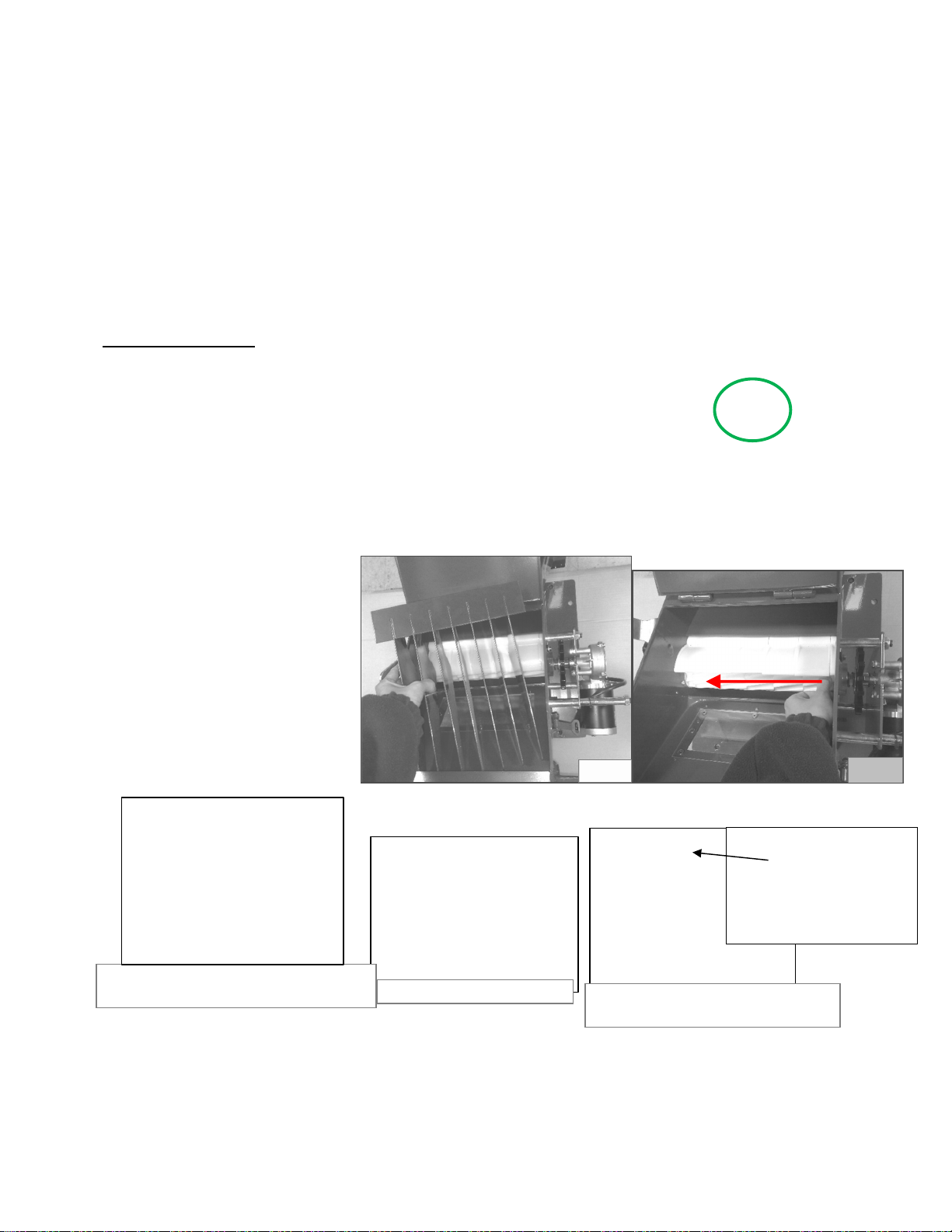
Changing of seed roll
TP-TURBO-JET Super 6/10
1. Remove the covers for the gears!
2. Remove the gears – Remove marked *split pin! (Pict. 1)
3. Remove the bearing with the 3 screws (See markings-Pict. 1)
5. Open the bottom flap and remove the lamella. (Pict. 2)
6. Push out the seed roll from below and fit the correct seed roll from outside.
TAKE CARE TO THE AXIAL TOLERANCE!
8. Fix the bearing,
Mount the geards,
Mount the split pin,
Mount the cover for the gears.
9. Check the axial tolerance
(When the bottom flap is opened)
10. Check after 2 hours
the screws and the split pin.
4. Fit the correct seed roll. Take care to the axial tolerance!
5. Mount the bearing.
6. Mount the split pin.
7. Mount the cover with the two nuts.
The position oft he spreader plates can be
horizontal or vertical.
Mounting the hose on the spreader plate.
Pict. 2
Pict. 3
1. Open the tow nuts and remove
the cover. 2. Remove safety split pin.
3. Remove bearing and remove the
seed roll.
If necessary open the
bottom flap and
remove the lamella.
Push out the seed roll
from inside.
Either
horizontal
Or vertical
10
8. Check the axial tolerance! (When the bottom flap is opened)
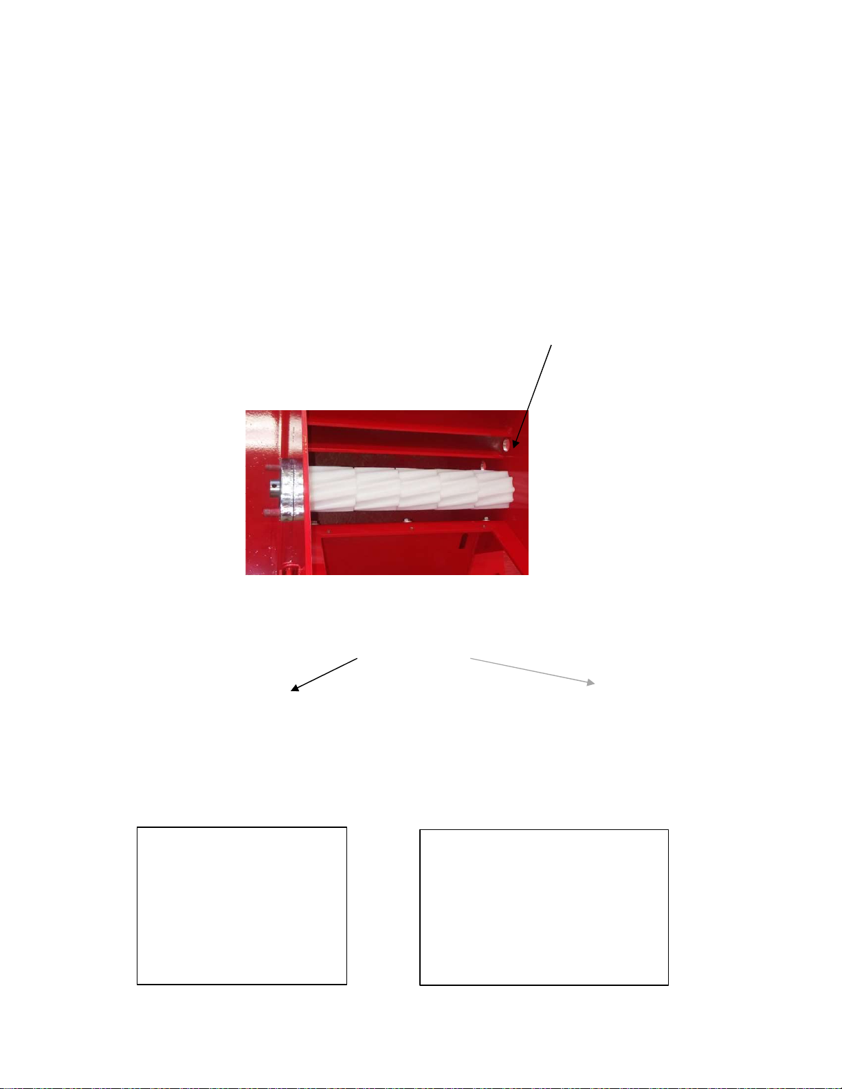
Dear Ladies and Gentlemen!
Plastic extends at high temperature and lowers less when cooling.
Please check when using the machine:
The seed roll must have axial play.
The plastic gears must have 0,4 to 0,5mm play between plastic gear and hexagon (left and right side) seed
axle.
Are this distances (plays) to low an unstable seed output is possible or the seed roll can stick.
0,4 to 0,5mm play

11
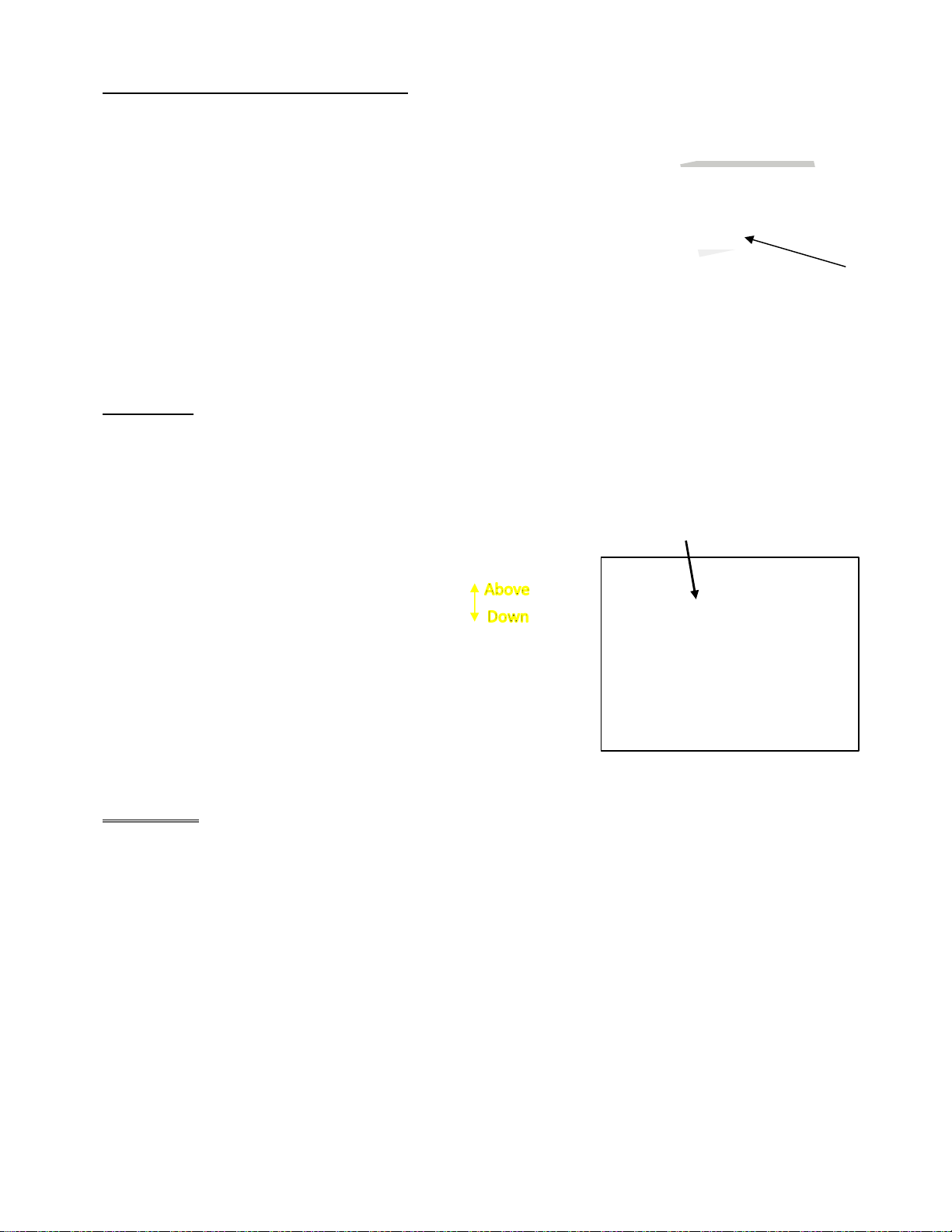
Bottom flap:
Bottom flap is closed = small seed
z.B: grass seed, rape, oil radish, lucerne, …
Open the bottom flap up to the marking for big seed
z.B: vetch, pea, wheat, rye, oat, beans, sun flower, barley, buckwheat, …
For emptying open the bottom flap complete.
Mesh to keep foreign objects away from the
seed roll.
Clumpy fertilizer or seed is taken back to
guaranty an equal material flow near the seed
roll.
12
Combination – Bottom flap with seed roll:
Between the plastic bottom flap and the seed roll should be a distance of
0,2 mm. The seed roll shouldn´t rub on the bottom flap.
The stainless steel bottom flap with stopper must be pressed to the seed roll to stop the full elements.
Just the geared seed roll elements turn.
Cover sheet:
For correct output amount take care on following point:
Above the seed roll is the adjustable cover sheet. It can be moved upward or downward.
For small seed put it in the lower third.
The quicker the seed roll turns the more move the cover sheet upward. So the seed roll is surely
completely filled every turn.
ATTENTION!!
Do this Adjusting before calibrating the machine. Otherwise the seed output amount is not correct.
Page 11 of 26
Metall seed roll with
plastic bottom flap.
Standard seed roll
with
plastic bottom flap.
Seed roll for small amount with
stainless steel bottom flap with
stopper.
Adjusting knob
Cover sheet

13
Hydraulic system with SEEDER+ control unit:
The hydraulic system on the fan is configured for max. 50lit/min and the motor
for max. 25lit/min.If this amount is exceeded, the fan can be damaged.
– NO WARRANTY!
Put the return pipe and the leak oil line absolutely non-pressurised to the
hydraulic. Non though a double-acting-control-unit.
Note that oil filters of tractors can produce pressure.
ATTENTION!
The hydraulic motor turns with 4000 rpm when the valve is
entirely open. To get the best air flow and avoid damages on
The best air flow and avoid damages on the fan adjust the valve
Before starting always at an oil operating temberature of
60-80° ba following this instucion:
1. open lock nut/threaded pin
2. Close the valve with the adjustable screw till it is
entirely closed. Turning the screw in (clockwise)- close
Turning the screw out (counterclockwise) open
3. Open the valve slowely till 1,5-2,0 turns (max. 3000 rpm on the fan wheel)
4. Check that the lock nut /threaded pin is closed tight again to avoid
self-adjustment of the oil volume
Hydraulic system with PROFI-Control unit
Seeder+/Twin the fan speed can be controlled on the display (see Seeder+/Twin instruction).
When using Profi control unit adjust the speed with a revolution counter to 2000 rpm.
V
alve
Lock nut/treaded pin
Adjustable screw
Connection to oil
cooler
Non-pressurised return
tot he hydraulic
Leak oil line non-
pressurised to
the hydraulic
The hydraulic system on the fan is configured for max. 50
lit/min and the motor for max. 25 lit/min.
Is this volume exceeded the fan can be damaged – No
WARRANTY
Put the return pipe and the leak oil line absolutely non-
pressurised to the hydraulic. Not through a double-acting -
conrol-unit.
Note that oul filters of tractors can produce pressure.
ATTENTION!
The hydraulic motor turns with 4000 rpm when the valve is
entirely open. To get the best air flow and avoid damages on
the
fan adjust the valve before starting always at an oil operating
temperature of 60°-80° by following this instruction:
1. Open lock nut/threaded pin.
2. Close the valve with the adjustable screw till it is
entirely
closed. Turning the screw in (clockwise)-close
Turning the screw out (counterclockwise) – open
3. Open the valve slowely till 1,5-2 turns (max. 3000 rpm
on the fan wheel)
50 bar approximate 2.000 U/min
smallseeded plant to 30 bar

14
Important hints for laying cables:
Put the cables in rolls!
Don´t bend the cables near sockets!
Take care when the implement is folded.
Cable can breakaway or clamp!
Avoid strong pulls on the cables! Don´t bend
the cable not to strong. Avoid clamps on the cables.
Use cable protection as needed!
Mount the control unit in a good position to reach it easy. Possible for mountings are cable ties or a locally done
bracket. Protect against moisture.
! Don´t mount inside the danger area!
Page 12 of 26

15
16
PROFI CONTROL UNIT
Speed knob:
For adjusting the speed on the seed roll motor=adjusting of output amount. The amount cann be
changed during operation
The seed roll motor speed = output amount can be adjusted stepless with this Poty. This can be done during
operation too to get the correct output amount. (Because of technical reason 0-3 without function.)
Calibration of the seeder:
Before start working the seeder must be calibrated. Note this adjustings for future operations (driven speed,
output amount, working width, poty adjustment, ...). Keep the fan turned off. Open the bottom flap on the
seeder (two spanner nuts). Let the flap hang downwards and put a vessel for collection below. (Be sure that
you have weighed this vessel). Fill in a small amount of seed into the seeder and close the hopper cover. Now
switch the seed roll on (Main switch to on and choosing a poty position, press the red button). Collect the
seed for 1 minute and weigh it accurate. The seed roll flap must be in correct position! Now calculate with
following formula how many kg per min have to be in the vessel.
Working width x Driven speed x Output amount/Ha
600
z.B.:
6m x 7km/h x 20kg/ha
600
6 x 7 = 4,2 ha/h x 20 kg/ha = 84 kg Output amount/h : 60 min
Is an amount of 1,4 kg/min which should be in your vessel.
z.B.: You know the working width, the driven speed and the output amount per hectare. As above mentioned
you can put in the different values into the formula and you get the needed amount. During calibration the
seed roll motor must run with the same speed during operation. Keep the cover closed! Is the calibration
done, close the bottom flap with the two spanner nuts.
1
= Output amount in kg/min
= 1,4 kg/min
1
2
3
4
Cable to
seeder
Battery cable
5
On-/Off-sensor
17
2. Main switch: This switch opens all functions on the unit.
WHEN WORKING ON THE MACHINE DISCONNECT POWER SUPLY!
3. For switching ON/OFF the seed roll and fan: When pressing this button the fan turns on first and after
some seconds the seed roll starts turning. Press the button again for switching off. The seed roll stops and
after some seconds the fan turns off. This avoids blocking in the hoses.
Red LED on left side shines = Seed roll and fan is turned on
Green LED on right side flashes = Seed roll turns
4. Calibration function: Only the seed roll turns on/off. Just for using during calibration. Don´t use in
general operation because the fan isn´t working, the hoses will block.
5. This button activates the ON/OFF sensor.
Yellow LED shines = sensor is active
Mounting of the ON/OFF sensor
The sensor stops the seed roll when no metal is opposite and switches the seed roll on when metal is
opposite. Sensor-DM: 12mm; max. reacting distance: 2mm. Check if the sensor has contact. When the
sensor has contact the led must shine. Be sure that the sensor switch off (Led dosn´t shine)
Activation and Dectivation of ON/OFF sensor:
Switch off the unit with the main switch. Wait about 2 seconds. Switch on again and press immediately the
yellow button for 2-3 seconds. When the yellow LED shines the sensor is active. Isn´t it shining the sensor
is not active.
6. Fuses in the unit
For fan: 15A
For seed roll motor: 10A
PROFI-CONTROL inside
ON/OFF-Sensor
Metal, min. size of
M8 screw head.
max. 2 mm
light
1
1. Switch is up – on
2. Red light is on
3. Please check the fuse.
2
3
. 1. Switch is at the bottom = circuit board is
deactivated
1.
+
-

18
Mounting possibilities On-/Off-sensor
Too short cables can be extended locally or ordered in a new length from us. Check following points when
extending the cables locally:
- Use the correct cross-section!
- Plugs and connections must correspond to the requirements.
- Plugs and connections must be mounted correct (No free wires, good isolation)
- Damages because of plugs and extensions mounted by the customer are NO warranty claim!
8
Configuration plug:
Electric fan
Nr. 54: Blue cable (– from relay)
Nr. 58L: Brown cable (+ from relay)
Nr. 31: Cable No. 1 (– from the unit)
Nr. 58R: Cable No. 2 (+ from the unit)
Hydraulic fan
Nr. 54:
Nr. 58L:
Nr. 31: Cable No. 1 (– from the unit)
Nr. 58R: Cable No. 2 (+ from the unit)
58L
31
54
58R
9
Electric/Hydraulic fan
Cable No. 1 = minus
Cable Nr. 2 = plus
30A fuse for electric fan used in the cable to battery plus
15A fuse for hydraulic fan used in the cable to battery plus
10
Configuration socket:
Electric/Hydraulic fan
Nr. 54 to minus
Nr. 58 L to plus
Nr. 31 to minus
Nr. 58 R to plus
11
Configuration socket:
Electric fan
Nr. 1 LED
Nr. 2 Seed roll motor +
Nr. 3 Seed roll motor -
Nr. 4 Relay +
Nr. 5 Relay -
Configuration socket:
Hydraulic fan
Nr. 1 LED
Nr. 2 Seed roll motor +
Nr. 3 Seed roll motor -
Nr. 4
Nr. 5
19
1
5
6
7
4
8
2
3
9
10
13
15
13
14
20
21
16
17
18
19
16
11
12
AN/AB Sensor
Geschwindigkeitssensor
Zählradsensor
Anschluss zu
Säwellenmotor
Gebläsesensor
1
5
6
7
4
8
2
3
9
10
13
15
13
14
16
17
18
11
12
20
21
18
19
22
23
AN/AB Sensor
Geschwindigkeitssensor
Zählradsensor
Anschluss zu
Säwellenmotor
Anschluss zu
Doppelturbine
SEEDER+ / TWIN Unit
The speed sensor
reacts to metall
.
For measuring the speed the sensor needs impulses (f.e. screw heads)
That screw heads can be mounted on a roller or the inner side of the tractor rim of wheel. The calculation
value is shown in mm/impulse. The driven way from impulse to impulse must be between 1 and 500.
Tractor wheel
Driven way:
Driven way from impulse to impulse
Calculate the needed screw heads as follows:
F.e.: Your wheel/roller with a diameter of 2m. -> Range (Diameter x 3,14 = range) is 6,28m = 6280mm. The
maximum driven distance from impulse to impulse must be below 500. Because of that (6280/500=12,56)
minimum 13 signals are needed. We recommend to use 20 signals. The signals can be mounted in any
radius. The only thing: The sensor must switch off between the signals.
Connection to
battery
Connection
to battery
Sensor cable with
red marking is for
on/off sensor
(linkage sensor)
Sensor cable with
red marking is for
on/off sensor
(linkage sensor)
READ THE SEPERATE OPERATION
INSTRUCITION AS WELL
SEEDER+/TWIN
Connection for
Seed roll motor
Connection for
double fan
Seed roll sensor
On/off sensor
Speed sensor
Connection for
Seed roll motor
Connection for
double fan
Seed roll sensor
On/off sensor
Speed sensor
20
Mounting possibilities speed sensor:
Check the impulses/signals before first use.
Attention! The sensor must count every signal (light shines) (Pict 1) and switch off between the signals
(light off) (Pict 2)
Errors
:
1. If the light doesn´t shine the distance between sensor and metal can be to big (max. 4mm).
2. If the light doesn´t turn off, the distance between the impulses is too small. Mount the impulses in a bigger
radius.
The on/off sensor stops the seed roll if there is no metal on opposite. If there is metal opposite the
sensor the seed roll turns. Sensor diameter: 30mm; max. reacting distance: 8mm. Check the sensor as
follows: Is metal opposite the sensor the light on the sensor must shine. Otherwise the light doesn´t
shine.
On/Off-sensor
metal
max. 8 mm
light
Pict. 1: Light shines! Pict. 2: Light off!
Table of contents


