TechnipFMC TRIPLEX M06 User manual

Doc No: OMM50001243
Rev: C Page 1 of 68
This document and all the information contained herein are the confidential and exclusive property of TechnipFMC,
and may not be reproduced, disclosed, or made public in any manner prior to express written authorization by TechnipFMC.
OPERATION AND MAINTENANCE MANUAL, M06 & M09 TRIPLEX
PUMPS
Rev
ECN No.
Date
Reviewed By
Approved By
Status
C
5044404
07-NOV-2017
Rothe, Michael
McClain, Mathew
RELEASED
Summary:
This is a manual for FMC M06 and M09 triplex plunger pumps. These pumps have a
stroke length from 1.50 inches to 2.25 inches and a maximum continuous duty power
rating from 16.6 horsepower (12.4 kilowatts) to 26 horsepower (19.4 kilowatts). Refer to
part number 5266227 for printing information.

Doc No: OMM50001243
Rev: C Page 2 of 68
This document and all the information contained herein are the confidential and exclusive property of TechnipFMC,
and may not be reproduced, disclosed, or made public in any manner prior to express written authorization by TechnipFMC.
Table of Contents
1.0 Important Safety Instructions ...................................................................... 6
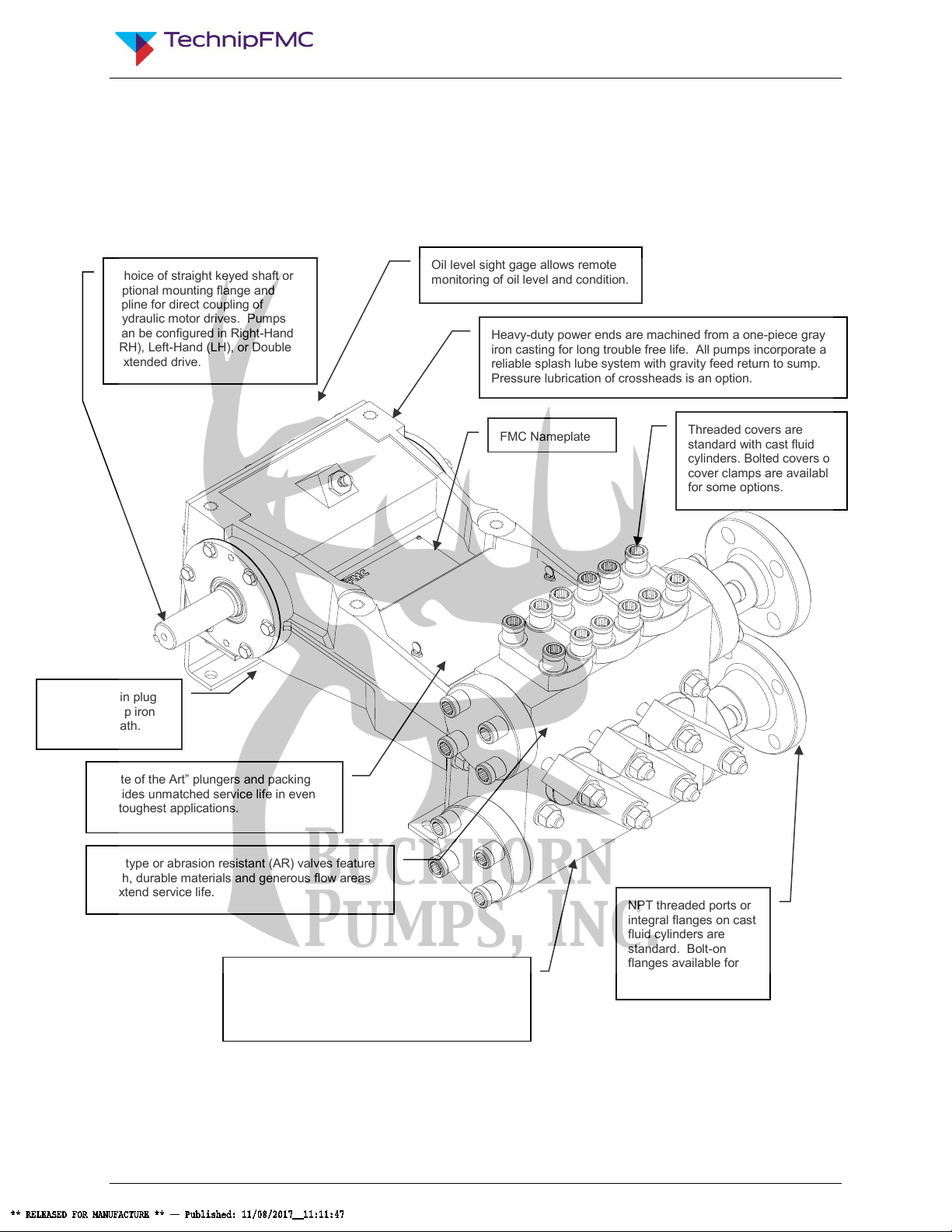
2.0 M06 Pump Features ...................................................................................... 7
3.0 Storage Instructions ..................................................................................... 8
3.1 Short Term Storage ................................................................................... 8
3.2 Short Term Storage for Severe Environments ........................................... 8
3.3 Long Term Storage.................................................................................... 9
3.4 Returning a Stored Pump to Operation...................................................... 9
3.5 Precautions during Freezing Weather ....................................................... 9
4.0 Installation Guidelines ................................................................................ 10
4.1 General Location ..................................................................................... 10
4.2 Mounting Pump to Foundation and Power Source .................................. 10
4.3 Suction Piping Recommendations ........................................................... 11
4.4 Discharge Piping Recommendations ....................................................... 13
4.5 Multiple Pump Systems ........................................................................... 14
5.0 How to Start a Pump ................................................................................... 14
6.0 Lubrication of Power End........................................................................... 17
6.1 Recommended Lubricants ....................................................................... 17
6.2 Oil Changes ............................................................................................. 17
7.0 Inspection and Preventative Maintenance Chart...................................... 18
8.0 Estimated Life of Wearing Components ................................................... 20
9.0 Component Parts List................................................................................. 21
10.0 Service Procedures..................................................................................... 26
10.1 Replacing Plunger Packing...................................................................... 26
10.2 Removing the Fluid Cylinder.................................................................... 30
10.3 Replacing Valves ..................................................................................... 32
10.3.1 Replacing AR Valves ............................................................................... 34
10.3.1.1 Introduction ....................................................................................................................... 34
10.3.1.2 Knock Out Tool ................................................................................................................. 35
10.3.1.3 Eccentric Discs.................................................................................................................. 36
10.3.1.4 Threaded Type (AR Valves Only) ..................................................................................... 40
10.3.1.5 Installation of AR Valves ................................................................................................... 41
10.3.2 Replacing Disc Type Valves .................................................................... 42
10.3.2.1 Introduction ....................................................................................................................... 42
10.3.2.2 Valve Removal Tools ........................................................................................................ 43
10.3.2.3 Installation of Disc Valves ................................................................................................. 44
10.3.3 Valve Removal and Installation Tools ...................................................... 44
10.4 Servicing the Power End.......................................................................... 45
10.4.1 Replacing Plunger Rod Oil Seals and Plunger Rods ............................... 45
10.4.2 Servicing the Connecting Rod Bearings .................................................. 46
10.4.3 Servicing Bearing Housings, Crankshaft, and Crossheads...................... 49
11.0 Fastener Torque Requirements ................................................................. 57

Doc No: OMM50001243
Rev: C Page 3 of 68
This document and all the information contained herein are the confidential and exclusive property of TechnipFMC,
and may not be reproduced, disclosed, or made public in any manner prior to express written authorization by TechnipFMC.
12.0 Critical Clearances...................................................................................... 58
13.0 Trouble-Shooting Pumps ........................................................................... 59
14.0 Ordering Parts ............................................................................................. 62
15.0 Glossary of Commonly Used Terms ......................................................... 63
16.0 Reference Information ................................................................................ 66
17.0 Maintenance Records ................................................................................. 67
17.1 Check List for Starting a Pump ................................................................ 67
17.2 Maintenance Log ..................................................................................... 68

Doc No: OMM50001243
Rev: C Page 4 of 68
This document and all the information contained herein are the confidential and exclusive property of TechnipFMC,
and may not be reproduced, disclosed, or made public in any manner prior to express written authorization by TechnipFMC.
List of Illustrations
Figure 1: Pump Assembly Features ............................................................................................7
Figure 2: Power End Components ............................................................................................21
Figure 3: Fluid End Components (Forged Style) .......................................................................22
Figure 4: Fluid End Components (Std. Cast Style) ....................................................................23
Figure 5: Plunger and Packing Removal ...................................................................................29
Figure 6: Fluid Cylinder Removal ..............................................................................................31
Figure 7: AR Valve Assembly....................................................................................................34
Figure 8: Using the Knockout Tool ............................................................................................35
Figure 9: Valve Disassembly.....................................................................................................36
Figure 10: Eccentric Disc in Use ...............................................................................................37
Figure 11: Removing the Seat...................................................................................................38
Figure 12: Hydraulic Power used to Remove Valve Seat ..........................................................39
Figure 13: Threaded Tool in use ...............................................................................................40
Figure 14: Typical Disc Valve Assembly....................................................................................42
Figure 15: Illustration for the Ball Knock Out Tool .....................................................................43
Figure 16: Back Cover Removal ...............................................................................................48
Figure 17: Connecting Rod Cap and Shell Bearing Removal ....................................................48
Figure 18: Bearing Housing, Gasket, and Shim Removal..........................................................50
Figure 19: Crankshaft Removal.................................................................................................51
Figure 20: Connecting Rod and Crosshead Removal................................................................53

Doc No: OMM50001243
Rev: C Page 5 of 68
This document and all the information contained herein are the confidential and exclusive property of TechnipFMC,
and may not be reproduced, disclosed, or made public in any manner prior to express written authorization by TechnipFMC.
List of Tables
Table 1: Pipe Pressure Chart ....................................................................................................13
Table 2: Recommended Drip Lubrication Rates ........................................................................16
Table 3: Lubricant Recommendations.......................................................................................18
Table 4: Maintenance Chart ......................................................................................................19
Table 5: AR Valve Tool Guide...................................................................................................44
Table 6: Disc Valve Tool Guide.................................................................................................44
Table 7: Torque Values for Critical Pump Fasteners .................................................................57
Table 8: Clearance Chart ..........................................................................................................58

Doc No: OMM50001243
Rev: C Page 6 of 68
This document and all the information contained herein are the confidential and exclusive property of TechnipFMC,
and may not be reproduced, disclosed, or made public in any manner prior to express written authorization by TechnipFMC.
1.0 Important Safety Instructions
Many accidents occur every year through careless use of mechanical equipment. You
can avoid hazards associated with high pressure equipment by always following the
safety precautions listed below.
•Shut down or disengage the pump and all accessory equipment before
attempting any type of service. Failure to do this could cause electrical shock or
injury from moving pump parts or components under high pressure. Always
adhere to "Lock Out" and "Tag Out" procedures. For mobile equipment, be sure
engines and hydraulics cannot be accidentally started.
•Bleed off all pressure to the pump and piping before performing any
maintenance on the pump. Failure to do so may spray water or chemicals at high
pressure or high temperature onto service personnel.
•Never operate the pump without a pressure relief valve, rupture disc, or other
type of properly sized over pressure safety device installed.
•Always use a pressure gaUge when operating the pump. The pressure must
never exceed the maximum pressure rating of the pump or damage may occur.
This damage can cause leakage or structural damage resulting in injury to
personnel.
•Ensure that no valves are placed between the pump and pressure relief
valve. If the pump is started with a closed or restricted valve in line before the
pressure relief valve, the pump may exceed the rated or design pressure limits
and rupture causing injury to personnel.
•Use shields or covers around pumps when pumping hot water, chemicals, or
other hazardous liquids. This precaution can prevent the exposure of service
personnel to these fluids should leakage occur.
•Always use guards on all belt drives, couplings, and shafts. Guards can prevent
personnel from becoming entangled and injured by rotating and reciprocating
parts.
•Use extreme caution with solvents used to clean or degrease equipment. Most
solvents are highly flammable and toxic. Observe all safety instructions on
packaging.
•follow normal environmental GUIDELINES when fluids, lubricants, or solvents
are disposed of or spilled.
•NEVER MODIFY THE PUMP to perform beyond its rated specifications without
proper authorization in writing from FMC.

Doc No: OMM50001243
Rev: C Page 7 of 68
This document and all the information contained herein are the confidential and exclusive property of TechnipFMC,
and may not be reproduced, disclosed, or made public in any manner prior to express written authorization by TechnipFMC.
2.0 M06 Pump Features
Exceptional design, workmanship, materials, and over 100 years of pump building
experience are features you'll find built into every FMC pump. The M06 pumps are
available with disc valves or abrasion resistant (AR) valves.
Figure 1: Pump Assembly Features
Choice of straight keyed shaft or
optional mounting flange and
spline for direct coupling of
hydraulic motor drives. Pumps
can be configured in Right-Hand
(RH), Left-Hand (LH), or Double
Extended drive.
Oil level sight gage allows remote
monitoring of oil level and condition.
Heavy-duty power ends are machined from a one-piece gray
iron casting for long trouble free life. All pumps incorporate a
reliable splash lube system with gravity feed return to sump.
Pressure lubrication of crossheads is an option.
Threaded covers are
standard with cast fluid
cylinders. Bolted covers or
cover clamps are available
for some options.
Disc type or abrasion resistant (AR) valves feature
tough, durable materials and generous flow areas
to extend service life.
“State of the Art” plungers and packing
provides unmatched service life in even
the toughest applications.
Magnetic drain plug
removes tramp iron
from the oil bath.
NPT threaded ports or
integral flanges on cast
fluid cylinders are
standard. Bolt-on
flanges available for
API pumps.
FMC Nameplate
Standard fluid cylinder materials of construction are
cast ductile iron or nickel aluminum bronze.
Forged steel or stainless steel fluid cylinders are
also available to cover a wide range of options.

Doc No: OMM50001243
Rev: C Page 8 of 68
This document and all the information contained herein are the confidential and exclusive property of TechnipFMC,
and may not be reproduced, disclosed, or made public in any manner prior to express written authorization by TechnipFMC.
3.0 Storage Instructions
Proper storage of your FMC pump will ensure that it is ready for service when started.
Follow the guidelines below that fit the requirements of your application.
FMC pumps come from the factory without crankcase oil and are prepared for storage
periods of up to six (6) months in proper environmental conditions. Indoor storage in a
dry, temperature-controlled location is always recommended. If pumps are to be stored
short term (less than six (6) months) in a severe environment, they should be prepared
using the procedures outlined in section 3.2. If the pump is to be stored, or is inactive,
for periods in excess of six (6) months, it is necessary to prepare the pump as outlined
section 3.3. Remember that any fluid that poses an environmental hazard or is toxic
must be handled and disposed of properly.
3.1 Short Term Storage
If the pump is stored in an indoor, temperature controlled environment for less than six
(6) months, no special steps are required to prepare it for storage. As a general rule for
pumps in corrosive fluid applications, the fluid end should be drained, flushed with water
or other non-corrosive cleanser and compressed air used to blow dry whenever idle.
3.2 Short Term Storage for Severe Environments
If the pump has been in service, drain any fluid from pump fluid end by removing the
plugs on the bottom of the fluid cylinder, flush the fluid end with water to clean out any
of the remaining pumpage and blow dry with compressed air. Drain the power end
(crankcase) oil and remove the oil fill cap (or plug). Pour 1 to 1-1/2 cups of internal rust
inhibitor oil described in Table 3 (Lubricant Recommendations), into the oil fill hole and
then install the non-vented filler cap or plug.
Pour 1/2 cup of internal rust inhibitor oil described in Table 3 (Lubricant
Recommendations), into the suction and discharge ports of fluid end, and then install
pipe plugs in openings.
Coat all exposed, unpainted metal surfaces (for example, Driveshaft) with preservative
oil. Cover the entire pump with a weather resistant covering such as a canvas or plastic
tarp.

Doc No: OMM50001243
Rev: C Page 9 of 68
This document and all the information contained herein are the confidential and exclusive property of TechnipFMC,
and may not be reproduced, disclosed, or made public in any manner prior to express written authorization by TechnipFMC.
3.3 Long Term Storage
Long-term storage is defined as any period when the pump is in storage or idle in
excess of six (6) months. If the pump has been in service, drain any fluid from the
pump fluid end, flush the fluid end with water to clean out any of the remaining
pumpage, and blow dry using compressed air. Pour internal rust inhibitor oil described
in Table 3: Lubricant Recommendations, into the suction and discharge ports of fluid
end, and then install pipe plugs in openings. Use the same quantity as described in 3.2.
Drain the oil from the pump power end. Remove the rear cover to expose the drive
components. Spray all internal parts with a rust preservative that is soluble in
lubricating oil while rotating the driveshaft several turns by hand to ensure complete
coverage. Replace the rear cover and add 1 to 1-1/2 cups of internal rust inhibitor with
those or equivalent recommended in Table 3.
Spray a rust preventative onto all exterior machined surfaces paying attention to any
unpainted areas like the crankshaft extension. Remove the oil fill cap and cover the
breather opening with a plug or other suitable means in order to keep the preservative
atmosphere sealed inside the power end.
Never store the pump on the floor or ground. Always place it on a shelf or pallet that is
several inches above ground level. Cover the entire pump with a canvas or plastic tarp.
Every two months inspect the unit. Rotate the crankshaft by hand at least 4 turns
during each inspection. Drain and replace the rust inhibitor after every six (6) months of
storage.
3.4 Returning a Stored Pump to Operation
Before operating a pump that has been prepared for storage, drain the preservative and
lubricating oil mixture from the power end (crankcase). Reinstall the drain plug,
breather/filler cap, and any other components that were removed for storage. Once
these steps have been completed, follow the normal pump start up procedures outlined
in this manual. NOTE: FMC can factory prepare units for long term storage for a
nominal fee if specified at the time of order.
3.5 Precautions during Freezing Weather
Freezing weather can cause problems for equipment when pumping water-based fluids
that expand in volume when changing from a liquid to a frozen solid state. When water
is left in a pump fluid end and exposed to freezing temperatures, the expansion of the
water as it freezes can rupture the fluid cylinder of the pump and cause equipment
damage. Injury may result when starting equipment that has been damaged.
Whenever the pump is stored or idle in conditions that are near or below freezing, any
water-based fluids should be removed from the pump. The best way to do this is to run
the pump for a few seconds with the suction and discharge lines disconnected or open
to atmosphere. This will clear the majority of the fluid from the pumping chamber as

Doc No: OMM50001243
Rev: C Page 10 of 68
This document and all the information contained herein are the confidential and exclusive property of TechnipFMC,
and may not be reproduced, disclosed, or made public in any manner prior to express written authorization by TechnipFMC.
well as the suction and discharge manifolds. After the run, blow compressed air
through the fluid end to remove all traces of fluid. If possible, remove plugs from the
bottom of the fluid cylinder and push open the suction valve seats to ensure that all fluid
is drained from the pumping chamber between the suction and discharge valves.
As an alternative to the previous procedure, a compatible antifreeze solution can be
circulated through the fluid end. RV antifreeze, propylene glycol, is recommended for
this purpose. Remember that any fluid that poses an environmental hazard or is toxic
must be handled and disposed of properly.
4.0 Installation Guidelines
A proper installation is essential to optimal performance, long service life, and reduced
maintenance requirements. Take time to thoroughly plan all aspects of your installation.
4.1 General Location
It is important to position the pump on as flat and level a surface as possible to assist
the splash oil lubrication system. Park mobile equipment, such as drilling machines, on
as level a surface as possible. Whenever possible the pump should be mounted in a
clean, dry location with sufficient lighting and adequate space for easy inspection and
maintenance. Locate the pump as close to the suction source as possible to allow for
the shortest and most direct routing of the inlet piping.
4.2 Mounting Pump to Foundation and Power Source
The M06 pumps described in this document must be mounted in a horizontal position
only. Secure the pump to the mounting surface using the four (4) holes provided in the
pump base. Check motor or engine rotation direction to ensure that the top of the pump
crank shaft rotates toward the pump fluid end when in operation.
For units that are V-belt driven, check the alignment of the sheaves after the unit is
installed on its permanent mounting. Tighten belts to the proper tension as
recommended by the belt manufacturer. Verify that the sheaves are in line and parallel
to each other with a straight edge.

Doc No: OMM50001243
Rev: C Page 11 of 68
This document and all the information contained herein are the confidential and exclusive property of TechnipFMC,
and may not be reproduced, disclosed, or made public in any manner prior to express written authorization by TechnipFMC.
CAUTION
Never operate the pump without a belt guard securely installed.
For direct-coupled or spline-driven units, ensure that the shafts are centered and
parallel when the driver is mounted to the pump. Follow the coupling manufacturer
instructions for installation procedures and tolerances.
4.3 Suction Piping Recommendations
Poor suction piping practices are a very common source of pump problems. To ensure
proper operation, it is very important to follow good design practice in the installation of
the suction system before the pump is operated. A small amount of additional planning
and investment in the piping system usually provides for better pump performance and
longer periods between service requirements. It is difficult to diagnose many pump
problems without the aid of a suction pressure gauge. For this reason, FMC
recommends that a gauge always be installed in the suction line directly before it enters
the pump.
The suction line from the fluid source to the pump should be as short and direct as
possible. Use rigid piping, non-collapsible hose or a combination of both as
circumstances require in your installation. The suction pipe size should be at least
equal to or one size larger than the pump inlet. Long piping runs, low suction heads, or
indirect pipe routing may require even greater over-sizing of the suction line for proper
operation of the pump. A suction pulsation dampener is recommended to reduce the
effects of acceleration head to help when suction conditions are not optimal. In some
cases it may be necessary to install a booster pump in the suction line of the pump to
obtain sufficient pressure for the pump to operate successfully.
The suction line must be configured so there are no high spots in the line where air
pockets can collect. These pockets may make the pump difficult to prime and cause
rough, erratic operation. A drain valve or plug should be installed at the low point of the
suction line to allow for draining before freezing conditions or for maintenance.
FMC recommends that all piping be supported independently of the pump. By
supporting the piping this way, vibrations are reduced and stress on the pump is kept to
a minimum. The use of elbows, nipples, unions, or other fittings should be minimized.
Make sure that all joints and connections are airtight. Air leaks reduce the capacity of
the pump and can result in cavitation, rough operation, and/or loss of prime. To help
isolate mechanical and hydraulic vibrations, FMC recommends the use of flexible pipe
couplings or hose connections between the pump and any rigid piping.

Doc No: OMM50001243
Rev: C Page 12 of 68
This document and all the information contained herein are the confidential and exclusive property of TechnipFMC,
and may not be reproduced, disclosed, or made public in any manner prior to express written authorization by TechnipFMC.
Always ensure that calculated system Net Positive Suction Head available, NPSHa,
exceeds pump Net Positive Suction Head required, NPSHr, by at least 5 feet (1.5
meters) of water for proper operation of the pump. NPSH requirements for each pump
model are provided on the product data sheets available through FMC or your
authorized FMC reseller. FMC does not recommend using the pump in static lift
conditions without prior factory approval.

Doc No: OMM50001243
Rev: C Page 13 of 68
This document and all the information contained herein are the confidential and exclusive property of TechnipFMC,
and may not be reproduced, disclosed, or made public in any manner prior to express written authorization by TechnipFMC.
4.4 Discharge Piping Recommendations
1. Route the discharge piping in as short and direct a route as possible. Use the
same pipe size as the outlet of the pump. In installations where the discharge
piping is in excess of 50 feet (15 meters) it is suggested to use the next larger
size pipe to minimize friction losses downstream of the pump.
Table 1: Pipe Pressure Chart
Allowable Working Pressure For Steel Pipe (PSI @ 100F)
Pipe Size
(inches)
Pipe Schedule Number
40
80
160
XX
3/8
1,700
3,800
1/2
2,300
4,100
7,300
12,300
3/4
2,000
3,500
8,500
10,000
1
2,100
3,500
5,700
9,500
1 1/4
1,800
3,000
4,400
7,900
1 1/2
1,700
2,800
4,500
7,200
2
1,500
2,500
4,600
6,300
2 1/2
1,900
2,800
4,200
6,900
3
1,600
2,600
4,100
6,100
14.5 psi = 1 Bar
CAUTION
Always use pipe or hose that is designed for your particular pressure
requirements. Inadequate pressure ratings can allow hose or pipe to fail,
resulting in equipment damage and possible personal injury.
Normal hose pressure ratings are clearly marked on the outer surface of
the hose. Working pressure ratings of steel pipe can be obtained from
the manufacturer or from the chart shown in Table 1 above.
2. Always use a pressure gauge in the pump discharge line. A properly functioning
gauge mounted at the pump (and before any valves) is required to accurately
determine the operating pressure of a pump and to conduct troubleshooting.
3. Ensure that all piping is supported independently of the pump to reduce vibrations
and strain on the pump. Pulsation dampeners on the discharge are
recommended to reduce pressure pulsation and resulting vibration. The use of
elbows, nipples, unions, or other fittings should be kept to an absolute minimum.
Avoid short radius 90elbows; use long radius elbows instead. To help isolate
and reduce mechanical and hydraulic vibrations, FMC recommends the use of
flexible pipe couplings between the pump and any rigid piping and the use of
pulsation dampeners.

Doc No: OMM50001243
Rev: C Page 14 of 68
This document and all the information contained herein are the confidential and exclusive property of TechnipFMC,
and may not be reproduced, disclosed, or made public in any manner prior to express written authorization by TechnipFMC.
4. A properly adjusted pressure relief valve or rupture disc must be installed
immediately downstream of the pump to prevent damage or injuries resulting from
over pressure or deadhead conditions. The relief valve discharge line must be as
large as the pipe outlet of the relief valve. Never install valves in the relief valve
discharge line or between the pump and relief valve. FMC recommends that the
discharge from the relief valve be returned to the tank or drain, not back into the
pump suction line.
5. It is recommended that a start-up bypass line and valve be installed in the
discharge line to allow flow to bypass the relief valve. This allows the pump to
start in an unloaded condition (no discharge pressure).
4.5 Multiple Pump Systems
Special consideration must be taken to avoid vibration, pulsation, or uneven flow
distribution problems when operating multiple reciprocating pumps using common
suction and discharge piping headers. It is recommended that the user contact FMC or
experienced industry consultants for assistance with the design of the system and pump
installation in these situations.
5.0 How to Start a Pump
CAUTION
Always take special precautions when starting a pump for the first time
or after any extended shutdown. Never assume that someone else has
properly prepared the pump and system for operation. Always check
each component of the system prior to every start-up.
The check list that follows is intended to be a general guide for starting a pump in a
typical installation. A copy of the check list is provided in Section 17.0 to allow it to be
copied and used at start up or at service intervals. Every installation is different, and
each may have different requirements to ensure safe and successful operation. It is
the responsibility of the operator to determine the correct start-up procedure for
each installation.
1. Ensure that the drain plug(s) on the bottom of the pump crankcase have been
installed and are tight. Ensure that the oil level sight glass, if equipped, has been
properly installed.
2. Check the oil level to ensure that the pump is properly filled with non-detergent
motor oil or a synthetic oil as described in Table 3 and that the oil has not been
contaminated with water or other contaminants.

Doc No: OMM50001243
Rev: C Page 15 of 68
This document and all the information contained herein are the confidential and exclusive property of TechnipFMC,
and may not be reproduced, disclosed, or made public in any manner prior to express written authorization by TechnipFMC.
NOTE
FMC pumps are shipped with no oil in the power frame and must be filled
to the proper level with the proper grade of non-detergent motor oil or
synthetic oil prior to start-up. Use Table 3 for selecting the correct type
of oil for your service.
Pump model M06 requires 2 quarts (1.9 liters) of oil
Pump model M09 requires 4 quarts (3.8 liters) of oil
3. Check to ensure that power is locked out and tagged out. Turn the pump over by
hand if possible to ensure free, unobstructed operation. Clean the plungers with a
soft cloth while rotating the pump by hand.
4. If the FMC pump is supplied with a factory mounted packing lubricator, ensure
that it is filled to the recommended level. Refer to Table 3 for the recommended
packing lubricant. Follow the vendor specifications for filling intervals and proper
maintenance. The recommended lubrication rates are specified in Table 2. Hand
operate each lubricator pump to provide initial lubrication to packing. It may be
necessary to bleed the lubrication lines from the lubricator to the stuffing boxes.
5. Check the plunger rods to ensure that they are free from abrasive particles or
debris.
6. Ensure that the pressure relief valve and all accessory equipment have been
installed and properly adjusted. Verify that all joints are pressure tight.
7. Open the suction line valve to allow fluid to enter pump. Prime the fluid cylinder if
necessary on the initial start up or after the system piping has been drained. The
valve covers may have to be cracked open to assist with priming. .
CAUTION
Do not loosen the valve covers with volatile or hazardous fluids.
8. Apply approximately 5-10 drops of glycerin or mineral oil to each plunger and
plunger rod to lubricate the packing and seals.

Doc No: OMM50001243
Rev: C Page 16 of 68
This document and all the information contained herein are the confidential and exclusive property of TechnipFMC,
and may not be reproduced, disclosed, or made public in any manner prior to express written authorization by TechnipFMC.
9. Make sure that all guards are in place and secure. Verify that all personnel are in
safe positions and that system conditions are acceptable for operation.
10. The pump is now ready to start.
NOTE
Whenever possible, use a bypass in the discharge line to allow the pump
to start in an unloaded condition (no discharge pressure). Slowly close
the bypass line to bring the pump into full load conditions. Shut down
immediately in if the flow becomes unsteady, pressure fluctuates, or if
unusual sounds or vibrations are noted.
11. Take temperature readings of the power end and stuffing boxes. Do not exceed
170° F (77° C) on power end. Do not exceed 160°F (71° C) on packing unless
packing is designed for hot fluid service.
Table 2: Recommended Drip Lubrication Rates
PLUNGER SIZE
(Inches)
Up to 1 1/2
1 1/2 to 2 1/2
DROPS PER MINUTE
8 to 10
12 to 14

Doc No: OMM50001243
Rev: C Page 17 of 68
This document and all the information contained herein are the confidential and exclusive property of TechnipFMC,
and may not be reproduced, disclosed, or made public in any manner prior to express written authorization by TechnipFMC.
6.0 Lubrication of Power End
6.1 Recommended Lubricants
Few factors can influence the life of a pump more than the power end lubricant (oil).
Careful selection of the right type of oil for each particular application will help ensure
optimal performance from an FMC pump.
The intent of this section is to state the general lubrication requirements for FMC
pumps. Several products are listed by manufacturer name in Table 3 below in order to
aid the customer in locating suitable lubricants. The following listing is not exclusive,
nor an endorsement of any particular product or manufacturer. Consult FMC for
lubrication recommendations for applications that fall outside of the conditions listed in
Table 3.
NOTE
Lubricant temperatures should not exceed 170° F (77° C) for continuous
duty or 180° F (82° C) for intermittent duty (less than 8 hours per day)
applications. Crankcase temperatures that exceed these limits will cause
the lubricant to prematurely "break down". The result will be poor
lubrication and failure of power end components, especially bearings.
The user should consider installation of a heating element such as those
furnished by Watlow® for cold ambient temperatures or a supplemental
oil cooler (heat exchanger) for high ambient temperatures.
6.2 Oil Changes
•Oil changes must be carried out after first 50 hours of operation, and
subsequently after every 4000 hours or at least every 6 months. These intervals
may be modified depending on actual operating conditions.
•Oil should be changed when hot to prevent build up of sludge deposits.
•It is advisable to check oil level daily. If more than 10% of the total capacity has
to be added, check for oil leaks.
•Do not mix oils of different types, even if produced by the same manufacturer.
•Never mix mineral and synthetic oils.
•To avoid the risk of scalding or burns, pay attention to oil and power end
temperature during an oil change.
•Follow environmental guidelines when changing and disposing of lubricants.

Doc No: OMM50001243
Rev: C Page 18 of 68
This document and all the information contained herein are the confidential and exclusive property of TechnipFMC,
and may not be reproduced, disclosed, or made public in any manner prior to express written authorization by TechnipFMC.
Table 3: Lubricant Recommendations
*Synthetic lubricants are suggested for high or low temperature service.
Cortecis a registered trademark of Cortec Corporation, St. Paul, NM
7.0 Inspection and Preventative Maintenance Chart
RECOMMENDED LUBRICANT CHART
Mineral Oil Lubricant
Synthetic Lubricant *
Type of
Service
Ambient
Temp
SAE
Grade
ISO
Viscosity
(cSt @ 40
C)
SSU
Viscosity
Manufacturer
Brand Name
SAE
Grade
ISO
Viscosity
(cSt @ 40
C)
Manufacturer
Brand Name
General
Service
0 F
to
100 F
(-18 C
to
38 C)
30
100
550
Texaco® Meropa
100
Shell® Omala 100
Shell® Rotella T
SAE 30
Exxon® XD-3 30 wt
Mobil® Trans HD-
30
5W-40
NA
90.0@40
15.0@100
99.1@40
13.9@100
Shell® Rotella T
Synthetic SAE 5W-40
Mobil® SCH 627
High Ambient
Temperature
Service
100 F
to
130 F
(38 C
to
54 C)
50
250
1165
Texaco® Meropa
68
Shell® Omala 220
Shell® Rotella T
SAE 50
Exxon® HD-3 50 wt
Mobil® Trans HD-
50
5W-40
NA
90.0@40
15.0@100
217@40
29.9@100
Shell® Rotella T
Synthetic SAE 5W-40
Mobil® SCH 630
Cold Ambient
Temperature
Service
0 F
to
-30 F
(-18 C
to
-34 C)
20
68
350
Texaco® Meropa
68
Shell® Omala 68
Shell® Rotella T
SAE 20
Exxon® HD-3 20 wt
Mobil® Trans HD-
20
5W-40
10W-30
NA
90.0@40
15.0@100
12.0@100
69.9@40
10.9@100
Shell® Rotella T
Synthetic SAE 5W-40
BP® Vanellus E8 ULTRA
5W-30
Mobil® SCH 626
Frequent
Start-Stop
Operation
40
150
775
Texaco Meropa®
150
SPECIALTY ITEMS
Internal Rust
Inhibitor
Cortec® VCI 329
External
Rust
Preventative
Texaco® Metal
Protective Oil L

Doc No: OMM50001243
Rev: C Page 19 of 68
This document and all the information contained herein are the confidential and exclusive property of TechnipFMC,
and may not be reproduced, disclosed, or made public in any manner prior to express written authorization by TechnipFMC.
Routine maintenance is an essential part of any successful pump operation. Properly
maintained FMC pumps are designed to offer years of trouble-free service.
Regular maintenance and inspection will keep your pump operating at peak
performance. FMC pumps have been carefully engineered to minimize maintenance
requirements and simplify these tasks when they are required. Regular inspections
allow operators to become familiar with normal pump operation so they can recognize
the signals of potential problems and schedule maintenance. The maintenance chart in
Table 4 shown below should be used as a guideline only. Many applications will require
adjustment of the intervals shown in this chart for severe or unusual operating
conditions.
Table 4: Maintenance Chart
Interval
Component
Service
Remarks
Break In
Crankcase Oil
Change
Drain and refill with new oil after first 50 hours of operation. Ensure
that the magnetic drain plugs are cleaned to remove debris.
Period
Inlet Strainer
Inspect
Clean if Required. The amount of material in the strainer will
determine the interval of cleaning.
Complete Pump
Inspect
General inspection of pump and system to check for proper operation
of equipment.
Daily
Packing sets
Inspect
Check the stuffing box area or cylinder liner area of the pump for
signs of leakage. Replace packing if leakage becomes excessive.
Pump System
Flush
Required for shutdown when pumping fluids that may harden or
corrode the pump if left inside once stopped.
Crankcase Oil
Inspect
Ensure that the oil is at proper level and has not been contaminated
by pumpage or condensation.
Weekly
Packing sets
Lubricate
If pump is supplied with grease zerks, apply grease to each fitting
every 100 hours or once per week.
Crankcase Oil
Change
Drain and refill with new oil. Clean magnetic drain plugs.
6 Months/
Stuffing Box Nuts
Inspect
Check the stuffing box nuts with a torque wrench to ensure they are
within specification.
4,000 hours
Connecting Rod
Bolts or Nuts
Inspect
Check the connecting rod bolts or nuts with a torque wrench to ensure
they are within specification. This should be done in conjunction with
oil change.

Doc No: OMM50001243
Rev: C Page 20 of 68
This document and all the information contained herein are the confidential and exclusive property of TechnipFMC,
and may not be reproduced, disclosed, or made public in any manner prior to express written authorization by TechnipFMC.
8.0 Estimated Life of Wearing Components
The information given here is an estimate of the average wear life of listed components
in clean liquid service. It is not a guarantee of life for any given application, but is
intended to facilitate maintenance schedules and stocking of spares. The maintenance
of the power end lubrication system will influence the life of the power end components.
The speed of operation and percent of maximum allowable load will influence the life of
both power end and fluid end parts. The temperature, abrasiveness, and lubricity of the
liquid affect the life of fluid end expendables.
POWER END COMPONENT ESTIMATED LIFE (Hours)
End and Main Bearings (Roller or Ball) 40,000
Wrist Pin Bushings 20,000
Crossheads 20,000
Lubrication pump 20,000
Power End Cover Gasket 10,000
Connecting Rod Bearings 10,000
Crankshaft Oil Seals 10,000
Oil Seal on Plunger (Pony) Rod 5,000
FLUID END COMPONENT ESTIMATED LIFE (Hours)
Stuffing boxes 16,000
O-Ring Seals 10,000
Valve Assembly 10,000
Packing adapter rings 8,000
Plungers 8,000
Packing 4,000
This manual suits for next models
1
Table of contents
Popular Water Pump manuals by other brands

SPX
SPX PE17 Series operating instructions

GORMAN-RUPP
GORMAN-RUPP GHC Series Installation, operation and maintenance manual

LK Armatur
LK Armatur SmartSolar LK 201 instruction manual

Graco
Graco SaniForce 1040 Repair parts list

Ismatec
Ismatec Reglo-Quick ISM 897 Quick start manual

Brenar
Brenar 5920 instruction manual