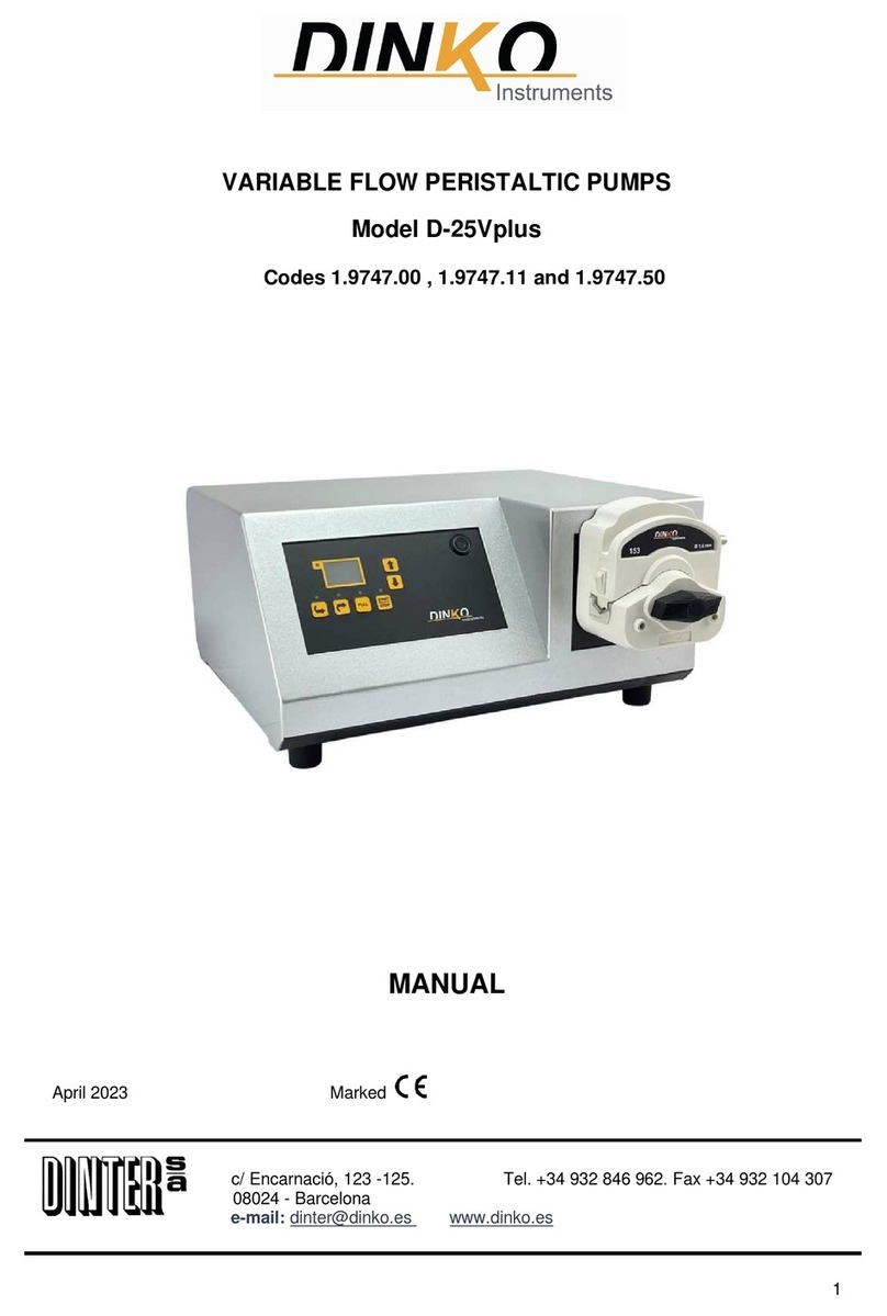
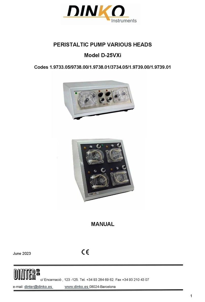
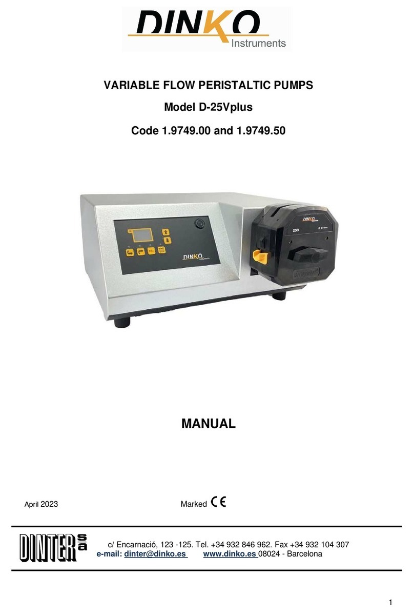
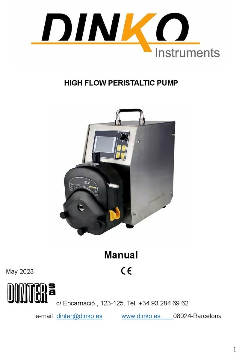
DINKO Instruments D-25VT User manual

1
PERISTALTIC PUMPS VARIABLE FLOW D-25VT
INSTRUCTION MANUAL
Rev. August 2022
c/ Encarnació, 123 -125. Tel. +34 93 284 69 62. Fax +34 93 210 43 07

2
INDEX
Page
1- General Introduction 3
2- Packing List 3
3- Descrip tion 3
4- Signals and Symbols 3
5- Pump Heads 4
5.1- Pump head 50 4
5.2 Pump Head CF-Opening 4
5.3- Tube loading: CF Pump head 4
5.4- Pump Head 1500-2r 4
5.5- Pump head- MC 4
5.6- Assembly pump head- MC 5
5.7- Pump head 5000-2r 6
6- Operating 7
7- Remote Control 7
8- Change Tubes 7
9- Ordering Information 8
10- Flow Tablets 8
11- Cyclic Timer 9
11.1- Menu selection 9
11.2- Modes of use 11
11.3- Run and stop time selection 11
12- Maintenance / Spares 12
13- Change Fuse 13
14- Troubleshooting 13
15- Warranty 13
16- CE-Declaration of Conformity 14
17- Other DINKO Apparatus 15

3
1-GENERAL INTRODUCTION
The following considerations have as purpose to guarantee a correct reception and use the apparatus, as well as the
security of the user. We recommend to read this manual detailed before proceeding to unpack the apparatus and later use.
-This manual should be conserved permanently within reach of the user.
- To unpack the apparatus carefully. Check that the content coincides with the packing list. Notify any eventuality
immediately.
- For the correct conservation of the apparatus it is necessary to avoid their installation in areas with corrosive
atmospheres or exposed liquid splashes.
- To avoid the use of the apparatus when the possibility exists to generate mixtures of explosive and inflammable gases.
-The European norm for use 89/655/CEE it exempts the maker all responsibility when it lacks an appropriate
maintenance or there is alteration or change of some component.
-The apparatuses that are sent to the Technical DINKO Instruments Service they will be perfectly clean and disinfected.
Otherwise, they will be rejected and returned with freight in charge of the owner.
2-PACKING LIST
Description Code Quantity
Peristaltic Pump D-25VT 1. 9732.XX /1. 9736.XX /1.9737.15/ 1.9745.XX /1.9767.50 /1.9768.50 1
Tube/terminals 3
Cable plug 1
Instruction Manual 1
Warranty 1
3-DESCRIPTION
Unitized instruments contain a peristaltic pump, speed control, cyclic timer, reverse and full flow switch, remote control and
on-off switch in a single case.
The peristaltic pumps D-25VT has a head that facilitates the extraction of the tube when it should substitute or for
sterilisation. In the code pump 9736 retires the cover extracting the three screws. Code pump 9745 has a pump head CF-3r,
5000-2r or MC for easy change tube. Each pump admits four or six tube sizes giving the flows ranges in the table.
The pump code pump 1.9737.15 retires the cover extracting the three screws. Wall thickness tube for 1500-2r head pump
and 5000-2r should be of 2,4mm. Also, for the code pump 1.9745.24 with pump head CF-3r
4-SIGNS AND SYMBOLS
At all times heed the danger warning signs and symbols that will appear in this manual or on labels attached to the pump
body such as those shown below
SIGNS/ SYMBOLS
INTERPRETATION
-
MEANING
Avoid finger contact with moving parts
Danger-Risk-Caution
Before remove cover
PULL-OUT plug
Before accessing inside of the Pump, disconnect the power cable
from the mains.
Possible overheating - Do not touch
230V AC 50/60Hz AC power supply voltage
110V AC 60Hz AC power supply voltage
12V DC or 24V DC DC power supply voltage
Disposal of waste electrical and electronic equipment by users
within the European Union.
It is not disposable as household waste.
Deliver to the agency for the recycling of electronic equipment.
Contact the local office, the store where you purchased the
equipment, or your household waste disposal service.
Recycling helps conserve natural resources.
Make sure it is recycled protecting human health.

4
5- PUMP HEADS
Back plate
5-1 Pump head 50
Screws Connectors
Rotor axis (rotor not showed)
Housing
Tube
5-2 Pump head CF: Opening
Only CF-3r pump head
1- Tube clamp setting.
2- Tube wall thickness
3- Set for tube bore size
5-3 Tube loading: CF Pump head
X- Not well installed tube
V- Well installed tube
5-4 Pump head 1500-2r
Cover fixing screws
5-5 Pump heads MC
Clamping levers of the micro tubes
Lever to remove the pump head

5
5-6 Assembly pump head MC

6
5-7 Pump head 5000-2r -Description and adjustment.
1 Lock 5 Flexible rotor lid 9 Roller
2 Protection lid 6 Hose guide roller 10 Tube clamp
3 Track 7 Rotor 11 Tube clamp
4 Clutch button lid 8 Support roller 12 Protection gasket
13 Drain
Remove rotor.
◊ Open protection lid and remove pump head hoses.
◊ Open flexible black lid located on the rotor centre.
◊ With a Phillips screwdriver to remove the central screw positioning.
◊ Pull the rotor hub off its axis.
◊ Between the hub and the shaft is a split collet. If the collet is retained by the shaft, pull it off, loosening, if necessary, using
light strokes. Do not try to remove it by prying with a screwdriver. If the collet is retained within the bucket, remove, if
necessary, slightly loosen the screw reinserting central locating and tapping the screw head.
Rotor replacement.
◊ Reassemble the split collet on the shaft, rotating it until it is fully inserted. Fit the body of the
rotor drive shaft as a unit.
◊ Open the flexible black cover of the centre rotor. With a Phillips screwdriver to tighten the
screw positioning a pair of 3 Nm to prevent the collet slipping during work. If the assembly
is correct, the guide rollers of the hose should be aligned with the outer surface of the track.
Close the flexible lid rotor.
◊ Close the cover and make sure the rotor is separated from it, watching the first rotation of the rotor.
Placing the tubes (hoses)
The 5000 pump heads are factory set to accommodate tubes from 1,6mm wall. Pumping performance may be adversely
affected if the tubes are not used right.
◊ Check hose length 225mm. to be placed inside the head. Please note,
if you put more than 225mm can be seen shortened tube life.
◊ Open the bottom clamp (spring) and put the hose to the first mark
of 225mm. aligned with the inside of the bracket that has the dock.
Loosen the clamp.
◊ Disengage the rotor clutch fully depressed the yellow button on the side of the rotor hub and rotor
turning the hub a few degrees, while maintaining the button. Now the rotor can give a complete
revolution independently of the gearbox and engine. If the clutch re-engages before the hose is
fully assembled, press the button again and turn the rotor a few degrees.

7
◊ Place the tubing around the track head, turning the rotor properly. Make sure the hose is not twisted or pinched between
the guide rollers and track. Check that the second mark of the 225mm. is located along the inner edge of the upper clamp.
◊ Open the upper hose clamp with spring and place the hose, making sure the hose does not twist and is supported
centrally between the guide rollers of the hose. Loosen the clamp
◊ Hose clamps, with spring, holding the hose must be strong enough to keep it from
Moving in or out of the pump head, but should not be tightened too much or choke the
passage of fluid. The clamps have a yellow slide that can be placed in two positions
while the clamps are open. The external position allows tightly hold the hose clamps,
while the inner position leaves him weaker. Adjust the sliders to prevent tube
movement during a test a few turns the rotor.
◊ Close the cover by pushing it fully until the latch engages
◊ Remember that it is appropriate, after 30 minutes of operation, tighten the hose back,
which can lengthen as it accommodates.
Tighten the hose so that the 225mm. hose are located between the parts of the hose
clamp that carry spring.
6- OPERATING
1. - Consult the table of dosages and install the appropriate tube (see maintenance section).
Remove the plastic cover of the pump head. Installing the tube with their terminals of fixation. When you settle the new
tube, should remain centred on the rollers to avoid the rotor to break the tube. Place the cover again. With each pump the
sizes of tube are giving. The feeding and discharge tubes could have any thickness of wall. But the tube that settles in the
pump head should have 1,6mm thickness of wall, except for pump head 1500-2r pump, 5000-2r and CF-3r with code pump
1.9747.24 which uses tube of 2,4mm wall thickness.
2. - Proceed to the programming of the cyclic timer. Seeing Description.
3. - Make sure that the voltage is 240V. Insert feeding and discharge tubes in the terminals of the pump head. Turn the - O -
reverse flow control button. Choose the speed acting on the digital speed control. Digital speed control can be set 0 - 99% in
1 % increments with 100 % repeat accuracy. Connect the cable plug. Push ON.
Because the friction of the tubes with the rollers increases with the tube diameter, the adjustable minimum speed increases
as much as big is the tube. Starting from the tube of 4,8mm the necessary minimum speed is the following one: tube 4,8mm
/ 5%, tube 6,4mm/10 %, tube 8mm/15 %.
It is not convenient to use smaller speed although the motor starts up since in any moment it can stop and to cause an
excessive heating of the regulation circuit that could be damaged if it remains in this situation for a lot of time.
When you use several CCF-3r pump head simultaneously in the pump 9745, tube diameter could be limited especially in
tubes of high hardness
7- REMOTE CONTROL
In the rear part of the pump there is a connection for a foot switch that is given as accessory with the order code 1.9740.02
When push the foot switch the dosage begins.
8- CHANGE TUBES
Press OF switch. Pump head 50: remove the three screws. To take out the tube together with their terminals of fixation. The
new tube should be centered on the rollers to avoid that the rotor breaks it. To take advantage of the turn of the slow rotor to
introduce the new tube. It is avoided this way to force the motor-axis when one tries to place the tube with the stopped rotor.
Take care
During the first minutes of operation some tubes, newly installed, undergo an elongation that alters the distances of
the tube and their fixings with the rollers. Readjust the tube in the pump head to prevent the rollers break the tube
unexpectedly.
Marking the tube with a marker makes it easier to detect a faulty attachment of the tube to their pump head which
will cause the tube to break through the rollers.
Place again the cover. Pump head CF, see “Description section”.
The supply and discharge tubes can have any thickness wall, but the tube that settles in the pump head should have a
thickness wall of 1,6mm. For pump with pump head 1500-2r and 5000-2r the wall thickness is 2,4mm. Also pump code
1.9745.24 with especial pump head CF-3r for 2,4mm thickness wall tube.
All the pumps are supplied with medical /alimentary degree silicone tube according to FDA norms and USP. It can sterilise.
Range of use until 250º C and half duration.

8
Other available materials are:
FARMED Long life. Medical / food grade. Free of plasticizers. Non-toxic or hemolytic. Suitable for high pressures
Compatible with chemicals, alcohols, and solvents. Autoclavable. Maximum temperature 135ºC
TYGON A-60-C ® Long life. Compatible with disinfectants and cleaning products. Resistant to acids, alkalis, oxidizing
agents such as Oxygen, Ozone, Peroxides and Hypochlorite’s. Food grade.
Autoclavable repeatedly. Temperature of use -59ºC to 135ºC. Beige colour
TYGON A-60-G ® Great resistance to fatigue and abrasion Compatible with Ozone, UV light and disinfectants. Resistant
to acids, alkalis and alcohols Use for vacuum. Temperature to use -59ºC to 135ºC. Black colour
SILICONE The most versatile tube. Platinum Cured Silicone. Medium duration. Medical / Food grade. Excellent
Biocompatibility. Autoclavable. Maximum temperature 140ºC. Translucent
TYGON L ® Long life. Non-toxic. Food / medical grade. Great chemical resistance to inorganic acids such as
alkalis, acids, and salts, as well as ketones, alcohols, detergents, disinfectants, and cleaning products
Autoclavable up to 5 times. Maximum use temperature 165ºC. Crystalline translucent
TYGON F-4040 ® Appropriate for gasolines, hot oils, kerosene and glycols. Yellow colour. Max. temperature 74ºC.
VITON ® Appropriate for acids and non-acetonic solvents. Black colour. Maximum temperature 300ºC.
9-ORDERING INFORMATION
All to 240V 50/60 Hz
Peristaltic pump D-25VT, pump head CF-4r. 10rpm. Code: 1.9732.25
Peristaltic pump D-25VT, pump head CF-4r. 80rpm. Code: 1.9732.26
Peristaltic pump D-25VT, pump head 50-3r. 30rpm. Code: 1.9732.05
Peristaltic pump D-25VT, pump head 50-3r. 80rpm. Code: 1.9736.80
Peristaltic pump D-25VT, pump head 50-3r. 240rpm. Code: 1.9736.00
Peristaltic pump D-25VT, pump head 1500-2r. 270rpm for 2,4mm thickness wall tube. Code: 1.9737.15
Peristaltic pump D-25VT, pump head CF-3r. 110rpm. Code: 1.9745.11
Peristaltic pump D-25VT, pump head CF-3r. 270rpm. Code: 1.9745.00
Peristaltic pump D-25VT, pump head CF-3r. 270rpm for 2,4 mm thickness wall tube. Code: 1.9745.24
Peristaltic pump D-25VT, pump head 5000-2r. 270rpm for 2,4 mm thickness wall tube. Code: 1.9745.51
Peristaltic pump D-25VT, pump head MC5-6r. Code: 1.9767.50
Peristaltic pump D-25VT, pump head MC10-6r. Code: 1.9768.50
10-FLOW TABLE. Regulation intervals for each tube diameter.
Code rpm
Head 0,5mm 0,8mm 1,6mm 3,2mm 4,0mm 4,8mm 6,4mm 8,0mm 9,6mm Tube
Ø
1.9732.25 10 CF-4r 0,01-0,25
0,03-0,62
0,2-2 0,5-6 0,7-9 -
Flow
ml/min
1.9732.26 80 CF-4r 0,15-1,8 0,4-4,5 1-15 4-40 7-57
1.9736.00 240
50-3r 0,6-5,2 1,5-16 5,6-65 25-225 35-283 70-400 130-700
- 1.9736.80 80 50-3r 0,15-2,2 0,4-5,6 1,3-24 3,8-73 5,9-114
8,9-145 16-258
1.9732.05 30 50-3r 0,05-0,8 0,13-2,0 0,6-7,5 1,5-23 2,1-35 3,2-45 5,7-81
1.9745.00 270
CF-3r 0,5-7,0 1,3-18 7,5-79 20-257 32-404 75-600 130-900 200-1300
-
1.9745.11 110
CF-3r 0,14-2,2 0,3-4,6 1,5-31 4,4-114
6,9-179
16-241 28-428 44-668
1.9745.24* 270
CF-3r 0,5-7,0 1,3-18 7,5-79 20-257 32-404 75-600 - - -
1.9745.51* 270
5000 0,12-1,8 3-28 14-112 43-449 68-705 100-999 165-1725 240-2760
348-4025
1.9737.15* 270
1500 - - - - - - 190-1700 400-2000
-
1.9767.50 110
MC5
1.9768.50 110
MC10
*For 2,4mm thickness wall tube *
Flow table pump head MC5-6r. Maximum speed 110rpm
Inside diameter mm
0,13
0,19
0,25
0,38
0,50
0,63
0,76
0,88
1,02
♦
1,14
1,29
Flow: ml / rpm
0,001
0,003
0,005
0,008
0,016
0,029
0,044
0,061
0,078
0,095
0,13
Max.
continuous flow ml/min
0,1
0,3
0,55
0,92
1,76
3,2
4,8
6.71
8.58
10,45
14,3
Inside diameter mm
1,42
1,47
1,52
1,65
1,85
2,05
♦
2,38
♦
2,54
2,79
3,00
♦
Flow: ml / rpm
0,16
0,17
0,18
0,21
0,26
0,32
0,38
0,45
0,52
0,58
Max. continuous flow ml/min
17,6
18,7
19,8
23,1
28,6
35,2
41,8
49,5
57,2
63,70
Flow table pumpm head MC10-6r. Maximum speed 110rpm
Inside diametre mm
0,13
0,19
0,25
0,38
0,50
0,63
0,76
0,88
1,02
♦
1,14
1,29
Flow: ml / rpm
0,001
0,003
0,004
0,008
0,013
0,024
0,035
0,048
0,06
0,08
0,09
Max. continuous flow ml/min
0,01
0,30
0,47
0,83
1,40
2,60
3,90
5,30
6,60
8,80
10,0
Diámetro interior tubo mm
1,42
1,47
1,52
1,65
1,85
2,05
♦
2,38
♦
2,54
2,79
3,00
♦
Flow: ml / rpm
0,11
0,12
0,13
0,15
0,18
0,22
0,26
0,30
0,33
0,36
Max. continuous flow ml/min
12,0
13,0
14,0
17,0
20,0
24,0
29,0
33,0
36,0
40,00
♦ Standard tubes, including a set of 12 units with the pump, diameter to choose.
Flows calculated with water in normal conditions without outlet back pressure.
• With the tube fixing lever moved from its vertical position the pressure is increased, but two to three times more Torque will be
required and the life of the tubes will be shortened.

9
11- CYCLIC TIMER
Before turning on the pump, place the motor rotation direction reversing control in position “0”.
When connecting the equipment, the timer turns on and waits. To start it, press the key ▲ (2)
OUT Open/closed contact indicator-red pilot light
15.00 - Measured time (red)
15.00 - Scheduled time (green)
Time units (hour-minute-second) H/M/S-green light
1 2 3 4
1 Button SET - 2 Increase button ▲ - 3 Scroll button► - 4 Reset button RST
The timer allows different working methods, depending on the selected menus.
11-1 MENU SELECTION
By pressing SET for more than 3 seconds you enter the Menu function. After selecting or modifying the parameter, press
SET and go to the next one. If you are more than 10 seconds without touching anything, it jumps to the original screen.
MENU SEQUENCE - Factory programming
rAn1
. Select units of By pressing ▲ decimals are selected
time and if they are
H.M.S and the maximum time for H.M.S or H/M . M/S
t. oFF (functioning) H from 99.99 to 9999
M from 99.99 to 9999
S from 99.99 to 9999
H/M 99.59
M/S 99.59
Press SET
rAn2 By pressing ▲ decimals are selected
Select units of and if they are
time H.M.S or H/M . M/S
H.M.S. and maximum for H from 99.99 to 9999
t.on (stop) M from 99.99 to 9999
S from 99.99 to 9999
H/M 99.59
M/S 99.59
Press SET
U-d By pressing ▲ is selected
Select the way U- Increase Mode
to count the time
d- Decrease Mode
Press SET

10
MENU SEQUENCE- Factory programming
i nt By pressing▲ is selected
Select response time 1 mS
20ms
Press SET
oUt
. Select the menu you want to use. By pressing ▲ is selected
n (Mode N) F( Mode F)
Description of the different modes
in the section MODES OF USE
C(Mode C) r( Mode R)
Press SET
StA By pressing ▲ is selected
Select start-up: YES- (When the equipment is connected,
you must press ▲ to start it up the first time
manual or automatic (manual)
No- When connected it starts up
automatically
Press SET
HoLd By pressing ▲ is selected
Selects that if the current power is lost,
on restart, follow the menu where it
was lost or start again Yes- Keep going
no- Start again
Press SET
By pressing▲ is selected
LoCY L-O-Nothing
Select ways to block the menu L-1-Block Reset
. L-2-Block time function and menu
..
L-3-Block all
Press SET

11
11-2 MODES OF USE
N-MODE
By pressing the foot switch or the RST key of the timer, the equipment will start up for the time programmed as t.oFF, which
is indicated in green by the programmed unit.
When it starts up, it will start counting the time (red numbers) and the green blinker will stay fixed. After the time has
elapsed, it will signal the time and the red signal will be on.
Start Stop M P
-----------------------
t.oFF t.oFF
RST RST
It is the appropriate mode for dosing by foot switch or button.
F-MODE
Same as the previous mode, but when the red numbers stop counting time.
R-MODE
Asymmetric cyclic method in which an operating time and a stop time are programmed. The operating time will be t.oFF
(closed contacts) and the stop time will be t.on (open contacts).
When starting the timer (press ▲) it will start counting the time t.oFF (contacts closed) of operation of the equipment with
the red digits, red light off and green light on.
Upon reaching t.oFF, it will stop for a time t.On (open contacts) with red digits, red light on, and green light flashing.
Start Stop M P M P
…………………
t.oFF t.on t.oFF t,on t.oFF………………………………
C MODE
Same as above but the green digits, programmed times, will only indicate the operating time.
11-3 RUN AND STOP TIME SELECTION
t. oFF and t. on indicates the status of the timer contacts.
To vary the conditions press ►
MENU SEQUENCE-
t. oFF
. Indicate that the contacts are closed The time parameters
and allow the equipment to 0,015 – 9999 H
function. Were selected in the
rAn1 of the 11enú.
Press SET
t. on The time parameters of
Indicates that the contacts are open 0,01S – 9999 H
and do not allow the equipment were selected in function
to function. rAn2 of the 11enú
It is indicated by a red pilot.
R and C menu only
The flashing number is selected with ▲ and moved to the next with ►. When all four digits are selected, press SET to
confirm.

12
12-MAINTENANCE / SPARES
Before proceeding to any exam or repair it is necessary to disconnect of the mains. All initiative should be made by qualified
personnel to avoid bigger wrongs.
Trust their apparatus to a technical service authorized by DINKO Instruments.
The motor and block of the dispenser pump don’t require lubrication for what they don’t have maintenance. It is convenient
to lubricate the rollers lightly with silicone grease.
The tubes should be replaced periodically to avoid the break.
Codes for calibrated tube of 1,6 mm wall thickness,1 meter.
Tube Ø 0,5mm 0,8mm 1,6mm 3,2mm 4,0mm 4,8mm 6,4mm 8,0mm
Farmapure 1.8700.16 1.8711.32 1.8700.48 1.8700.64 1.8700.80
Farmed 1.8710.05 1.8710.08 1.8710.16 1.8710.32 1.8710.48 1.8710.64 1.8710.80
Tygon A-60-C 1.8740.16 1.8740.32 1.8740.48 1.8740.64 1.8740.80
Tygon A-60-G 1.8750.16 1.8750.32 1.8750.48 1.8750.64 1.8750.80
Silicon 1.8760.05 1.8760.08 1.8760.16 1.8760.32 1.8760.40 1.8760.48 1.8760.64 1.8760.80
Tygon L 1.8770.16 1.8770.32 1.8770.48 1.8770.64 1.8770.80
Tygon 4040 1.8780.32 1.8780.48
Viton 1.8790.16 1.8790.32 1.8790.48 1.8790.64 1.8790.80
Codes for tubes (1,6mm wall thickness) and connectors. Pk of 5 units.
Tube Ø 0,5mm+ 0,8mm+ 1,6mm 3,2mm 4,0mm 4,8mm 6,4mm
Farmapure 1.8705.16 1.8705.32 1.8705.48 1.8705.64
Farmed 1.8715.05 1.8715.08 1.8715.16 1.8715.32 1.8715.48
Tygon A-60-C ®
1.8745.16 1.8745.32 1.8745.48 1.8745.64
Tygon A-60- G®
1.8755.16 1.8755.32 1.8755.48 1.8755.64
Silicon 1.8765.05 1.8765.08 1.8765.16 1.8765.32 1.8765.40 1.8765.48 1.8765.64
Tygon L ® 1.8775.16 1.8775.32 1.8775.48 1.8775.64
Tygon 4040 ® 1.8785.32 1.8785.48
Viton 1.8795.16 1.8795.32 1.8795.48 1.8795.64
+Packs of 0,5mm. and 0,8mm. 3 pieces, only for 50 pump head. For pump head CF, below.
Connector codes with 1meter tube (1,6mm thickness wall) and 2 stainless steel capillaries for CF-3r or CF-4r heads
Tube, inside Ø 0,5mm 0,8mm
Farmed 1.8710.15 1.8710.18
Silicone 1.8761.05 1.8761.08
For connectors of CF-3r or CF-4r heads with 0,5mm and 0,8mm Ø tubes longer than 1 meter acquire the tubes, see table,
and the capillaries code 1.0077.23, bag of 10 units, if required.
In the case of needing tubes with diameters greater than 0,8mm, see the tube table and acquire the tube and the white PP
connectors that are required:
White PP terminal connector for Ø tubes between 1,6 and 4,0mm Ø, for pump head 50. Code 1.0077.22 in bag of 10 units
White PP terminal connector for Ø tubes between 4,8 and 6,4mm Ø, for pump head 50. Code 1.0077.15 in bag of 10 units
White PP splice connector for Ø tubes between 4 and 6mm Ø. Code 1.0800.15 in bag of 10 units
White PP splice connector for Ø tubes between 4,5 and 8,2mm Ø. Code 1.0800.18 in bag of 10 units
White PP splice connector for Ø tubes between 8 and 10mm Ø. Code 1.0800.05 in bag of 10 units
White PP splice connector for Ø tubes between 10 and 12mm Ø. Code 1.0080.14 in bag of 10 units
White PP splice connector for Ø tubes between 10 and 15mm Ø. Code 1.0800.19 in bag of 10 units
Figure nr. 2 shows from left to right the head cover 50 with tube installed, a
connection / tube representing all tubes from 1,6 to 6,4mm diameter and a
connection / tube corresponding to 0,5 and 0,8mm diameter tubes provided of
loading / unloading capillaries of stainless steel
Fig. 1
Tubes for MC Pump head (indicate inside diameter tube). See table flows.
Pack Silicone tubing, 12 units. Code 1.8760.83
Tubes for pump head 1500, 5000 (2,4mm wall thickness tube)
Tube Ø.inside
0,5mm
0,8mm
1,6mm
3,2mm
4,8mm
6,4mm
8,0mm
9,6mm
Marprene ®
1.8713.16
1.8713.32
1.8713.48
1.8713.64
1.8710.82
1.8710.9
7
Silicone
1.8762.05
1.8762.08
1.8762.16
1.8762.32
1.8762.48
1.8762.64
1.8760.81
1.8760.
97
Tygon A
-
60
-
G ®
1.8756.48
1.8756.64
1.8756.80
1.8756.96
Viton ®
1.8791.16
1.8791.32
1.8791.48
1.8791.64
1.8791.80
1.8791.96

13
IMPORTANT: The tubing’s for the pump head should be greased lightly with silicone grease
Back plate 50. Code 1.0077.04 Button for flow reversing switch. Code 1.0025.01
Digital cyclic timer. Code 1.0045.13 Flow reversing switch and stop. Code 1.0015.05
Foot switch. Code 1.9740.02 Housing 50. Code 1.0077.03
Motor 10rpm CF-4r. Code 1.0079.03 Motor 80rpm CF-4r. Code 1.0079.02
Motor 240rpm, 50-3r. Code 1.0077.01 Motor 30rpm, 50-3r. Code 1.0077.24
Motor 80rpm, 50-3r. Code 1.0077.10 Motor 110rpm MC/ CF-3r. Code 1.0080.13
Motor 270rpm CF/1500/5000. Code:1.0080.01 Pump head MC5-6r. Code 1.0078.38
Pump head MC10-6r. Code 1.0078.39 Pump head 1500-2r. Code 1.0078.11
Pump head “CF-3r”. Code 1.0078.01 Pump head “CCF-3r” compl. Code 1.0078.02
Pump head CF-3r for WT 2,4mm. Code 1.0078.06 Pump Head CF-4r. Code 1.007822
Pump Head 5000 for WT 2,4mm. Code:1.0078.09 Rotor 50-3r. Code 1.0077.02
POWER SOURCES
For pump heads CF-4r and 50-3r. Code 1.8093.16 For pump heads 1500 and MC. Code 1.8093.17
For pump heads CF-3r and 5000-2r. Code 1.8093.21
13-CHANGE FUSE
The fuse box is part of the supply base located at the rear of the pump. See figure.
Base
Fusible
Interruptor
I O
Base/Fuse /Switch ON-OFF
Prying with a screwdriver between the central part of the box holder and the top of the supply base to remove the fuse box.
The box is subject not removed completely. There are two fuses.
Press the box inward to restore its original position.
14-TROUBLESHOOTING
The following table of faults, their causes and possible solutions, does not pretend to cover all possibilities.
However, user annoyances that actually have easily avoidable causes can be avoided.
PROBLEM
CAUSE
SOLUTION
It does not start and the pilot lights do not light
Lack of power
Blown fuse
Unknown
Check cable and plugs
Change fuse
Request Technical Service
The rotor of pump head does not turn, but the
lamps are lit
Broken tube that prevents it
Defective motor
Replace tube
Request Technical Service
Rotor rotates, tube is not broken,
but does not pump
Exhausted, worn tube
Insufficient tube wall
Empty feed tank
Chemical incompatibility of tube
Replace tube
Install suitable tube
Load the tank
Install suitable tube
Flow below theoretical
High viscosity
Excessive pump circuit
Internal obstruction in the tube
Insufficient tube wall
High discharge back pressure
Chemical incompatibility of the tube
Use a larger tube Ø
Shorten circuit
Clean up
Install suitable tube
Lower back pressure
Choose suitable tube
Head tube drifts Small tube diameter
Faulty tube installation
Choose suitable tube
Check the bindings
15-WARRANTY
WHAT IS COVERED:
This product is guaranteed to be free of defect in workmanship and materials under normal use for a period of one year from
the date of purchase by the consumer. During the warranty period, the manufacturer will repair or, at their option, replace at
no charge a product that proves to be defective, provided you return the product, shipping prepaid, to an authorized service
centre.
WHAT IS NOT COVERED:
Instruments subjected to misuse, buse, neglect or unauthorized repair or modifications will be excluded from this warranty.
Also excludes expendables, consumables. The liability of DINKO is limited to repair or replacement and in no event shall
DINKO be liable for any collateral or consequential damages or loss.

14
“CE” DECLARATION OF CONFORMITY
DINTER S. A. / DINKO Instruments c/ Encarnació, 123-125 / 08024 - Barcelona
Declare that the products mentioned in attached list, to which this declaration relates, comply with the essential safety
requirements of the relevant European Directive.
- Low Voltage Directive D2006/95/CEE, of December 12, 2006
-Essential requirements of Annex I of Directive for Machinery 2006/42/CEE, of May 17, 2006
- Electromagnetic compatibility (EC), relative to the Directive for electromagnetic compatibility 2004/108/CEE, of
December 15, 2004
-Safety for electrical devices of measurement, control, and laboratory use. Requirements concerning to CEM. EN 61326
-Safety rules for the electric devices of measurement, control, and laboratory use. Part I. General requirements EN 61010-1
Mounting and connecting instructions defined in catalogues and technical data sheets must be respected by the user
Name: Joan A. Bravo Josep X. Sensada
Position: Technical Manager Quality Manager
Signature:
Model: Peristaltic Pumps D-25VT

15
OTHER DINKO APPARATUS
- Colorimeters
- Extractor for mince analysis
- Heater Metallic Blocks
- Heater Plates
- Infrared Ovens
- Kits for Water Analysis
- Magnetic Stirrers.
- Nephelometers
- Orbital Shakers
- Peristaltic Pumps
- Photometers
- Respirometers BM
- Rod Stirrers
- Rotary Stirrers
- Sand Baths
- Spectrophotometers
- Temperature Controllers
- Timers
-Trichinoscopes
- Turbidimeters
- Turn Dishes
- Vacuum Pumps
c/Encarnació,123-125.
08024- Barcelona. Phone: +34 93 284 69 62 / Fax +34 93 210 43 07
Table of contents
Other DINKO Instruments Water Pump manuals

DINKO Instruments
DINKO Instruments D-25VXi User manual

DINKO Instruments
DINKO Instruments D-25VXi User manual

DINKO Instruments
DINKO Instruments D-25Vplus 1.9747.00 User manual

DINKO Instruments
DINKO Instruments D-25Vplus 1.9747.00 User manual

DINKO Instruments
DINKO Instruments A-60-F User manual

DINKO Instruments
DINKO Instruments D-25Vplus 1.9747.00 User manual
Popular Water Pump manuals by other brands

DROPSA
DROPSA BRAVO User Operating and Maintenance Manual

Graco
Graco Reactor 2 Series Operation

Regulus
Regulus CSE MIX W8-SC 1M Installation and operation manual

Clarke
Clarke CPE30A1 Operation & maintenance instructions

SKF
SKF JM Series Original operating instructions

caprari
caprari D Series Use and maintenance instructions