SFA SANIPUMP ZFS 71 Series User manual

Grinder pump
Operation manual
SANIPUMP®ZFS71
9030
02.2020

CONTENTS
Copyright / Disclaimer - SANIPUMP®ZFS 71 Installation and Maintenance Manual - Original operating instructions
All rights reserved. The contents of this document must not be reproduced, modified or disclosed to third parties except upon written consent from the
manufacturer. This document may be subject to change without notice. Status of the operating instructions: February 2020
1. SAFETY.....................................................................pg.4
1.1 Identifying the warning signs ...........................................pg.4
1.2 Personnel qualifications and training ...............................pg.5
1.3 Dangers from non-observance of the safety instructions.......pg.5
1.4 Safety-awareness at work................................................pg.5
1.5 Safety instructions for the customer/operator ....................pg.5
1.6
Safety instructions for maintenance, inspection and assembly work
.pg.5
1.7
Unauthorised re-equipping and spare-part production.........pg.6
1.8 Unauthorised modes of operation.....................................pg.6
2. GENERAL .................................................................pg.6
2.1 Scope...........................................................................pg.6
2.2 Queries and orders .......................................................pg.6
2.3 Technical data ...............................................................pg.6
2.4 Range of application .....................................................pg.7
2.5 Accessories ..................................................................pg.7
3. TRANSPORT AND TEMPORARY STORAGE ........pg.8
4. DESCRIPTION..........................................................pg.8
4.1 Motors..........................................................................pg.8
4.2 Pumps...........................................................................pg.8
4.3 Switching device (AC-powered model).............................pg. 8
5. INSTALLATION ........................................................pg.8
5.1 Electrical equipment .......................................................pg.8
5.2 Hydraulic system..........................................................pg.10
5.3 Level control system......................................................pg.11
6. COMMISSIONING ...............................................pg.11
7. MAINTENANCE AND REPAIR ............................pg.11
8. MALFUNCTIONS, CAUSES AND
TROUBLESHOOTING.................................................pg.11
9. GUARANTEE.........................................................pg.12
10. TECHNICAL MODIFICATIONS ..........................pg.12
Appendix A: Characteristic curves.......................................pg.13
Appendix B: Examples of installation
......................................
pg.13
Appendix C: Pump dimensions............................................pg.14
Appendix D: Sectional drawing and list of spare parts
...........
pg.15

4
1. SAFETY
WARNING
This device can be used by children who are at least 8 years old and
by people with reduced physical, sensory or mental capacities or those
without knowledge or experience, if they are properly supervised or if
they have been given instructions on safely using the device and the
associated risks have been understood. Children should not play with the
device. Children should not clean or perform maintenance on the device
without supervision.
ELECTRICAL CONNECTIONS:
The electrical installation must be done by a qualified electrical engineer.
The device's power supply must be connected to ground (class I) and protect-
ed by a high sensitivity differential circuit breaker (30 mA). Devices without
plugs must be connected to a main switch on the power supply which discon-
nects all poles (contact separation distance of at least 3 mm). The connection
must be used exclusively to provide the power to the product.
If the power cord is damaged, to prevent possible danger, it must be replaced
by the manufacturer, customer service team or a similarly qualified individual.
The operation manual at hand provides basic notes which have to be taken into account
during assembly, opera-tion and maintenance works. Therefore, before assembly and
commissioning, this operation manual has to be read by the assembler as well as the
responsible personnel/operator at all costs. It always has to be available on site of operation
of the machine/plant.
The general safety notes listed under the main point safety are not the only notes to be taken
into account. Please also observe the specific safety instructions, such as those for private
use, listed under other main points.
1.1 Identifying the warning signs
Danger
This term defines a high risk of danger, which can lead to death or
serious injury, if not avoided.
Dangerous area
This symbol characterises hazards that could lead to death or injury.
Dangerous voltage
This symbol characterises dangers associated with the voltage and
provides information on voltage protection.
Property damage
Thissymbol,incombinationwiththekeywordATTENTION,characterises
dangers to the machine and its proper operation.

5
It is imperative to observe signs that are attached directly to the machine (for example,
rotational direction arrow, sign for fluid connections) and must be kept fully legible.
1.2 Personnel qualications and training
The personnel responsible for operation, maintenance, inspection and assembly have to have
the corresponding qualifications for those types of work. Area of responsibility, competence
and the surveillance of the personnel have to be regulated precisely by the operator. If the
personnel do not possess the necessary knowledge, they have to be trained and instructed.
By order of the operator, the instruction and training, if necessary, can be carried out by the
manufacturer/supplier. Furthermore the operator has to make sure that the personnel have
completely understood the content of the operation manual.
1.3 Dangers from non-observance of the safety instructions
Non-observance of the safety instructions can result in danger to persons and damage to the
environment and the machine. Non-observance of the safety instructions can lead to loss of
any claims for damage compensation.
In detail, non-observance can for instance involve the following hazards :
• Failure of important machine/system functions
• Failure of prescribed methods for maintenance and repairs
• Danger to persons through electrical, mechanical and chemical hazards
• Danger to the environment through leakage of harmful substances
1.4 Safety-awareness at work
The safety instructions described in this Operating Manual, the valid national regulations on
accident prevention, and possible internal regulations of the customer on work, operation
and safety are to be observed.
1.5 Safety instructions for the customer/operator
• Hot or cold machine components which could cause danger have to be secured against
contact by the customer.
• Protective devices to prevent touching moving machinery (e.g. coupling) may not be
removed from operating machines.
• Leakage (e.g. shaft seals) of dangerous conveyed products (e.g. explosive, poisonous, hot)
has to be led off in such a way that there is no endangerment to persons or environment.
Legal stipulations are to be maintained.
• Hazards through electric energy are to be eradicated (for details, see national regulations
and those of the local power supply companies).
1.6 Safety instructions for maintenance, inspection and assembly
work
The customer has to ensure that all maintenance, inspection and assembly work is carried
out by authorised and qualified specialist personnel, who have been sufficiently informed
through relevant and adequate study of the Operating Manual.
Work on the machine is to be done on principle only when it is shut down. The procedure
for shutting down the machine is described in the Operating Manual and is to be precisely
adhered to.
Pumps, or pump units that convey hazardous media have to be decontaminated. Immediately
after finishing work, all safety and protective devices have to be re-attached and put into
effect.

6
Prior to initial (re-)start-up, you are to take heed of the points listed in the section Initial
Operation.
1.7 Unauthorised re-equipping and spare-part production
Re-equipment and modification of the machine are only permitted after consultation with the
manufacturer. Original spare parts and accessories authorised by the manufacturer are all
part of the safety strategy. Use of other parts can eliminate liability for the consequences
that ensue.
1.8 Unauthorised modes of operation
Operational safety of the delivered machine is only guaranteed when it is used appropriately
according to Section 2 - General in the Operating Manual. The limit values specified in the
data sheet may on no account be exceeded.
2. GENERAL
2.1 Scope
This operation manual is valid for the submersible waste water pumps SANIPUMP®ZFS 71.
If the instructions of the operation manual – especially the safety instructions - are
not observed, or in case of unauthorized modifications of the plant or the installa-
tion of non-original spare parts, the guarantee expires automatically. The manu-
facturer assumes no liability for damages resulting from such behaviour!
Manufactured sizes:
SANIPUMP®ZFS71.1S
SANIPUMP®ZFS71.1T
SANIPUMP®ZFS71.2T
SANIPUMP®ZFS71.3T
SANIPUMP®ZFS71.4T
2.2 Queries and orders
Please send your queries and orders to your specialist dealer.
2.3 Technical data
SANIPUMP®ZFS 71.1 S ZFS 71.1 T ZFS 71.2 T ZFS 71.3 T ZFS 71.4 T
Rated power P2[kW] 1.6 1.7 1.7 3.2 3.2
Voltage U [V] 230 400 400 400 400
Frequency [Hz] 50
Rated current consumption I [A] 10.5 3.7 3.7 6.5 6.5
Drive n [min-1] 2800
Max.discharge flow Qmax [m3/h] 17
Max. delivery height Hmax [m] 22 22 25 35 39
Max. media temperature tmax [°C] 40
Pressure connection (optional) Flange DN50
Weight with cable [kg] 38 38 38 44 44
Duty ratio ED S1- continuous operation (flooded), S3- 40% (emerged)
Minimum fluid level Bottom line of motor housing

7
Materials
Motor housing GG 20 Motor shaft 1.4021
Pump housing GG 20 Bearing flange GG 20
Cutting flange 1.4112 Impeller GG 20
Cutting knife 1.4112 Other seals NBR, FPM
Auxiliary bearing flange St 37-2 Floating-ring type shaft seal SiC
(silicon carbide
)
2.4 Range of application
The submersible waste water pumps of the type series SANIPUMP®ZFS 71 are used for the drainage of
sewage and wastewater tanks, excrement collection pits, sewage plants and the like in explosion-prone
areas.
In this context, the following has to be pointed out (Excerpt from DIN VDE 0165):
For the installation of electrical systems in explosion-prone areas, the “directive about electrical
installations in ex-plosion-prone areas” (ElexV) applies. Amongst other things, this directive regulates
the question of permitting ex-plosion-protected electrical equipment and the responsibility (admission) of
experts. (DIN VDE 0165 1.2)
When assessing the risk of explosion, that means when explosion-prone areas are defined, the „directives
for the avoidance of dangers caused by a potentially explosive atmosphere with collection of examples
– guideline on protection against explosion – (EX-RL)“ are to be taken into account. If it is a matter of
special cases, or if there are doubts about the definition of explosion-prone areas, the supervisory
authority has to decide. (DIN VDE 0165 1.1.2)
In case of medical areas, the DIN VDE 0107 (DIN VDE 0165 1.2) applies.
In case of the installation of electrical systems in areas which are endangered by explosive materials,
the DIN VDE 0166 (DIN VDE 0165 1.3) applies.
In case of the operation of electrical systems in explosion-prone areas, the DIN VDE 0105 part 9 (DIN
VDE 0165 1.4) applies.
This regulation does not apply for the installation of electrical systems in mine openings which can be
endangered by mine gas. Here, the norms of the set DIN VDE 0118 „Installation of electrical systems in
underground mining companies” (DIN VDE 0165 1.5) apply.
Terms:
- "Explosion-prone areas" are areas in which an explosive atmosphere can occur in endangering
quantities (dangerous explosive atmosphere) due to the local and operational circumstances (explosion
hazard) (DIN VDE 0165 2.1).
- "Explosive atmosphere" is a conglomerate of inflammable gases, vapours, mists or dusts including the
common additives (e.g. humidity) under atmospheric conditions, inside which a reaction independently
reproduces itself after ignition. Atmospheric conditions are total pressures of 0.8 to 1.1 bar and
conglomerate temperatures of -20 to +60°C. (DIN VDE 0165 2.2)
Please always refer to the national standards in force.
2.5 Accessories
All pumps of the type series SANIPUMP®ZFS 71 are delivered with 10 m of cable and free cable end.
Switching devices for pumps with explosion protection are available as standard or special models with
various level control systems.
For the installation of the pump, a supporting ring (primarily for transportable operation) or a coupling
device (stationary operation) is available.

8
3. TRANSPORT AND TEMPORARY STORAGE
On principle, the pumps SANIPUMP®ZFS 71 should be lifted and/or transported using the eyelets on
top or the handlebar designed for that purpose. Under no circumstances is the pump to be lifted on the
power supply cable!
For temporary storage and conservation, it suffices if the pumps are stored in a cool, dry, frost-protected
and dark place.
4. DESCRIPTION
4.1 Motors
The pumps SANIPUMP® ZFS 71 are equipped with an AC asynchronous induction motor or a three-
phase asynchronous motor. Temperature sensors, which function as temperature limiters, have been
integrated into each of the three motor windings. If the motor overheats for any reason, the bimetallic
contacts respond to this and the motor is switched off.
The motor is to be restarted solely by hand! However, the motor may only be restarted after an error
analysis has been conducted and the cause of malfunction has been eliminated.
The motors are certified by the BVS - Dortmund and have the following certificates of conformity:
BVS05ATEXE028X.
4.2 Pumps
The pump housing and the impeller are made of grey cast iron; the cutting device, which is
located in front of the impeller on the suction side, is made of a special alloy. This cutting device
comminutes suspended soils, so that they will not enter the pump and choke it. The pumps are
equipped with a flange DN 50.
4.3 Switching device
The pumps are delivered without switching device.
5. INSTALLATION
- Disconnect the power supply before carrying out any kind of
work on the plant!
- The electrical connections are not to be exposed to humidity!
5.1 Electrical equipment
The AC-powered model of the pump can be operated with an auxiliary switch device which is
equipped with the following elements: main switch, fuses, contactors, thermal motor protection relay,
operating capacitor, restart lockout for the clipping circuit, signal lamps „Betrieb“ (operation) and
„Störung“ (malfunction), Ex i - relay and a floater for the protection against dry running.
The pump is connected to an earthed wall socket with an earthed type plug by means of the cable which
is con-nected to the switching device.
9
- The switching device has to be installed outside the explosion-
prone area!
- The floater for the protection against dry running has to be
installed in such a way, so that a decline of the water level below
the bottom line of the motor housing is not possible.
Further electrical installation is not necessary. If required, the motor housing can additionally be earthed
by means of the external earthing terminal intended for that.
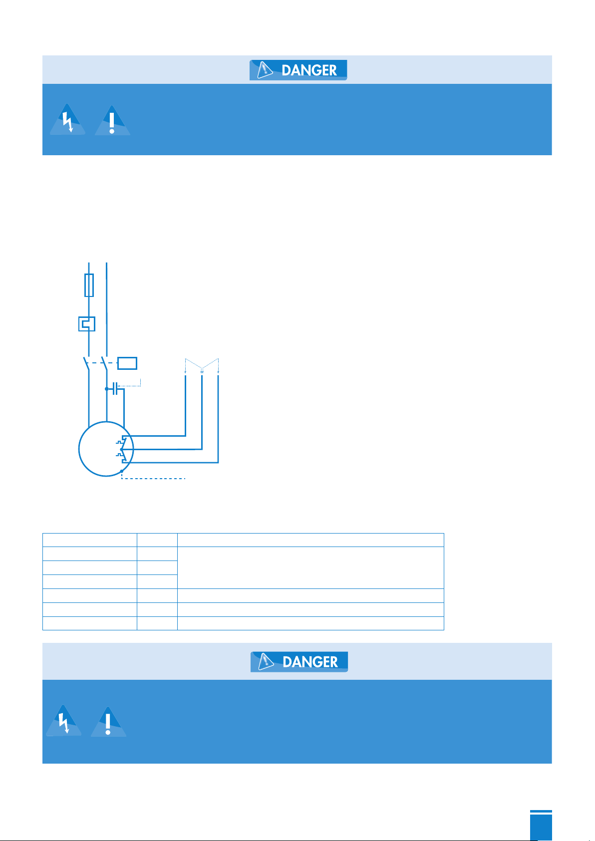
If an additional switching device is connected to the pump SANIPUMP®ZFS 71.1, it has to be connected
as follows:
1~ 230 V/50 Hz
1~
230 V
50 Hz
L1 N
U1
1
U2
2
TB1
4
TB2
5
TB3
6
Z1
3
M
Motor
protection
Fuse
MAINS
Motor
relay
Motor capacitor
Thermal winding protection
Control loop Clipping
circuit
Green/Yellow
PE conductor
Three phase model :
The wires of the seven-wire connection cable of the pumps (three-phase model) are marked as follows:
Green/Yellow PE Ground wire (earthing)
1 U1
Three windings, star connection2 V1
3 W1
4 TB1 Second contact control loop
5 TB2 Shared contact control loop and clipping circuit
6 TB3 Second contact clipping circuit
- The switching device has to be installed outside the explosion-
prone area!
- The floater for the protection against dry running has to be
installed in such a way, so that a decline
of the water level below the bottom line of the motor housing is
not possible.

10
Wiring diagram:
3~ 400 V/50 Hz
3~
400 V
50 Hz
L1
U1
1
TB1
4
TB2
5
TB3
6
M
L3L2
V1
2
W1
3
Motor
protection
Fuse
MAINS
Motor
relay
Thermal winding protection
Control circuit Clipping circuit
Green/Yellow
PE conductor
Connection of the thermal winding cover:
- Control loop : T1 and T2 must be connected in a switching device in such a way, that the following function
is guaranteed: When the temperature sensors respond, the pump is switched off until the tempera-ture has
dropped again. Now the pump is switched on again.
- Clipping circuit : T2 and T3 must be connected in a switching device in such a way, that the following
function is guaranteed: When the temperature sensors respond, (failure of the control loop), the pump is
switched off and can be restarted by hand solely. The pump may only be restarted after an er-ror analysis
has been conducted and the cause of malfunction has been eliminated.
Connection to the switching device PS1-LCD and PS2-LCD:
Switching
device PS1-LCD PS2-LCD
Pump 1 Pump 1 Pump 2
Switching device 20 21 22 31 32 33 38 39 40
Pump T1 T2 T3 T1 T2 T3 T1 T2 T3
5.2 Hydraulic system
These pumps are not to be mounted in dry installation, since a minimum
water level up to the bottom edge of the motor housing is prescribed by
the guideline on protection against explosion.
Installation with supporting ring:
- Mount supporting ring to intake flange of the pump and install pump. Ensure stability of the pump.
- Optionally connect pressure side by means of flange DN 50 or thread (The pump is equipped with a female
thread G2 and a flange DN 50).
- If a hose is to be laid on the pressure side, kinks are to be avoided.
- Avoid kinks during the laying of the supply cable. Lay supply cable without tensile loading and without
causing chafe marks.
Installation for shaft fitting:
- Position pipe clamp on inner rim of the shaft and loosely fix it with two screws.

11
- Sound out position of guide pipe frame for coupling pedestal, adjust coupling pedestal on shaft bottom and
mount it with the heavy-duty dowels which are included in the delivery.
- Install pressure pipe and valves in a tension-free manner.
- Slip the guide pipe on the coupling pedestal, shorten it to correct length, slip on pipe clamp and tighten it
for good.
- Mount coupling element and lowering chain to the pump, lower pump with the chain (insert guide pipe into
coupling element) and couple it, hang the chain up on the pipe clamp so that it is ready to hand.
- Lay supply cable. Avoid kinks and lay supply cable without tensile loading and without causing chafe marks.
5.3 Level control system
The pumps SANIPUMP®ZFS 71 have to be controlled by means of a level control in such a way, that a
decline of the water level beneath the minimum allowable level (bottom line of motor housing) is avoided at
all costs.
The level control can be effected by means of a floating switch, electropneumatically (press switch) or by
means of other applicable methods. The switching point of the pump should be set in such a way, that the
pump is entirely submersed under water.
If the level control is effected via a floating switch, the signal of the floaters has to be transmitted via
intrinsically safe Ex i –relays.
6. COMMISSIONING
Check all connections for correct assembly, set gate valve on passage and check level control system
for proper operation.
During the initial test run, check pipes for tightness and reseal them, if necessary.
7. MAINTENANCE AND REPAIR
Disconnect the power supply before carrying out any kind of
work on the plant!
After an operation time of six to twelve months, the oil storage inside the seal carrier always has to be
controlled as follows: put the pump on its side on a clean surface and position it in such a way that the
oil filling screw faces upwards. Take out the screw and check the oil level. If only a small quantity of
oil is lacking, the oil storage can be filled up without any problems. If a considerable quantity of oil is
lacking, or if the oil is mingled with water, the customer department has to be informed.
All other maintenance works on the pump and on the electrical equipment should be carried out by the
manufacturer or an authorised qualified company in intervals of six to twelve months (or also in shorter
intervals, according to case of operation). Please immediately inform the customer department in case
of damage to the pump and/or the electrical equipment.
8. MALFUNCTIONS, CAUSES AND TROUBLESHOOTING
Disconnect the power supply before carrying out any kind of work
on the plant !

12
Malfunction Cause Elimination
1. Motor is not
rotating - absence of line voltage or improper
line voltage - check voltage supply
- incorrect connection - correct the connection
- defective power cable - replacement (customer service)
- defective/wrong capacitor - replacement (customer service)
- impeller/cutting knife blocked - cleaning
- activated motor protection
(overheating, blocking, improper
voltage or other malfunction)
- inspection, inform customer
service
- control malfunction/defective floating
switch - inspection, inform customer
service
- motor defective - replacement (customer service)
2. Motor rotates but
does not convey - impeller blocked or worn out - cleaning/replacement
- check valve blocked - cleaning
- gate valve blocked/closed - cleaning/opening gate valve
- pressure pipe blocked/hose buckled - cleaning/eliminating kinks
- intake socket blocked - cleaning
- incorrect rotating direction - correction
- water deficiency inside the shaft - switch off/inform customer
service
3. Motor switches off
during start-up - voltage improper or unsteady - correction/customer service
- thermal protection laid out incorrectly - inspection/customer service
- current consumption too high - customer service
4. Motor does not
switch off - control malfunction - customer service
- wrong/defective floating switch - replacement/customer service
9. WARRANTY
As the manufacturer, we provide a warranty of 24 months on these pumps from date of purchase.
Your sales receipt will act as a proof of warranty. During that warranty period, we gratuitously remedy
all deficiencies which are attributed to material or fabrication defects by either repairing the plant, or
by replacing the defective parts (to our choice).
Defects which are attributed to misuse or wear are excluded from warranty. We will assume no
responsibility for consequential damages that are caused by a breakdown of the plant. In case of a
warranty claim, please contact your specialist retailer.
10. TECHNICAL MODIFICATIONS
We reserve all rights for technical modifications in terms of further development.
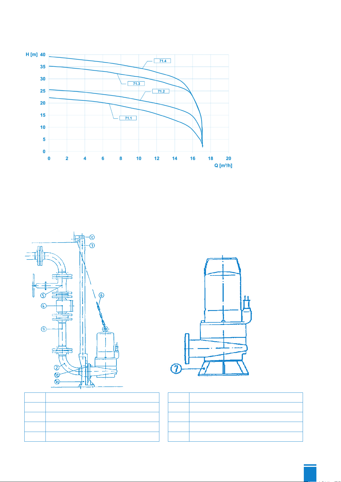
13
Appendix A: Characteristic curves
Appendix B: Installation suggestions
Fixed installation Portable installation
1a Coupling pedestal 4 Backflow preventer
1b Guide piece 5 Wedge-type flat slide valve
1c Pipe clamp 6 Lowering chain with clevis
2 Flange elbow 7 Supporting ring
3 Guide pipe 5/4'' 9 Pressure pipe
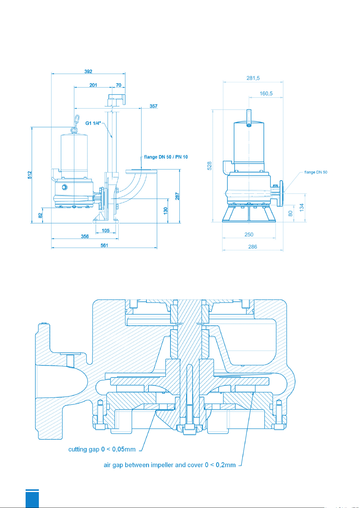
14
Appendix C: Pump dimensions
Fixed installation Portable installation
Adjustment values for cutting gap and pump hydraulics

15
Appendix D: Sectional drawing and list of spare parts

16
Pos. Art. Nr. Designation Quantity
1 17369 Motor complete SANIPUMP® ZFS 71.1 S 230 V 1
1 17368 Motor complete SANIPUMP® ZFS 71.1 T and ZFS 71.2 T 400 V 1
1 17370 Motor complete SANIPUMP® ZFS 71.3 T and ZFS 71.4 T 400 V 1
2 17356 GLRD LD1/25-G38 motor side 1
3 11679 Locking ring DIN471-A25x1,2 1
4 16381 Hexagon socket screw M8x25-A2 5
5 17377 GLRD MG1/25-G6 medium side 1
6 17373 Impeller ZFS 71.1 Ø135 1
6 17371 Impeller ZFS 71.2 Ø145 1
6 17372 Impeller ZFS 71.3 Ø160 1
6 17351 Impeller ZFS 71.4 Ø170 1
7 17350 Lid ZFS 71 1
8 17109 Countersunk screw M5x10-A2 DIN965 3
9 17352 Knife screwing ZFS 71 1
10 11640 Sealing screw, bea. G 3/8 (ventilation) 1
10 11639 Sealing screw G3/8 DIN910 (oil) 1
11 11663 Ring screw DIN 580-M8-A2 1
12 15320 Hexagon socket screw M6x20-A2 4
13 10008 Hexagon socket screw M6x10-A2 4
14 17355 Pump housing ZFS 71 1
15 17353 Cutting plate ZFS 71 1
16 17354 Cutting knife ZFS 71 1
17 11822 O-ring 160 x 3,5-NBR70 1
18 11629 O-ring 147 x 3 1
19 11672 Sealing ring 8x14x1 Cu 1
20 11659 Handle 1
21 10666 Hexagon socket screw M6x12-A2 DIN 912 2
22 17375 Shim ring 10x30x0,1 1.4301 2
22 17376 Shim ring 10x30x0,5 1.4301 2
23 11656 O-ring 125x2-NBR70 1
24 11646 Sealing ring 17x22x1,5 Cu für Pos 230 2
70 11645 Tooth lock disc S8x13x0,8 A2 4
11690 Wisura technical white oil NFW 0.4 L
Other manuals for SANIPUMP ZFS 71 Series
2
Table of contents
Other SFA Water Pump manuals

SFA
SFA SANILife Tray Matic User manual

SFA
SFA Sanipro XR User manual

SFA
SFA SANICUBIC 1 User manual

SFA
SFA Sanicom FF03-P95 User manual

SFA
SFA Saniswift Pro User manual

SFA
SFA SaniPump Manual

SFA
SFA Sanicondens Deco+ User manual

SFA
SFA SANIBROYEUR PRO User manual

SFA
SFA SaniAccess 3 User manual

SFA
SFA SFA SANISPEED User manual


