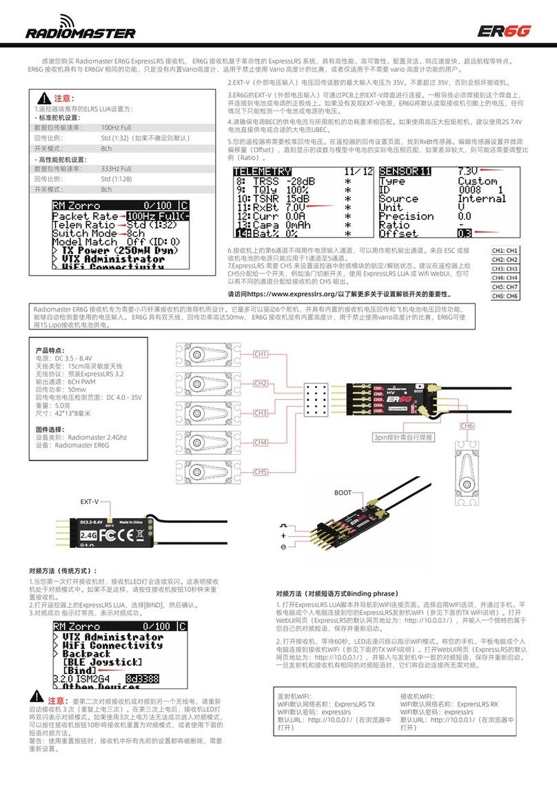
TECHNO-AC Success AG-511N Manual


2
Table Page of Contents
Introduction ........................................................................................................3
1. The general description ..................................................................................... 3
Specification АP-014 ............................................................................................. 4
2. Receiver AP-014 .................................................................................................. 5
2.1 General view and buttons mappi ................................................................... 5
2.2 Receiver control and indication modes .......................................................... 6
3. Electromagnetic sensor EMD-247 ...........................................................8
4. Transmitter AG-105 ...................................................................................................9
4.1. Purpose of use and physical configuration .............................................................. 9
4.2. Control and indication elements ..............................................................................10
4.3. Ways of external commutation ............................................................................... 13
4.4. Accessories .......................................................................................................... 13
4.5. Design and function ............................................................................................... 14
4.6. Illustrative use information about «Power supply monitoring», «Buttons functionality»,
«Symbols» ....................................................................................................................... 15
4.7. «Multimeter» of the output parameters ................................................................... 15
4.8. Sound signals .......................................................................................................16
5. Working with the device ............................................................................................ 1 6
5.1. Preparatory activities ............................................................................................. 16
5.2. Settings ................................................................................................................19
5.3. Clips ..................................................................................................................... 19
5.4. Internal transmitting inductor «In» . .......................................................................... 20
5.5. External induction transmitting antenna .................................................................. 20
5.6. Transmitting induction “clamp” ............................................................................... 21
5.7. External power sources ......................................................................................... 21
5.8. Electromagnetic compatibility ................................................................................. 22
5.9. Ingress protection rating ........................................................................................22
Transmitter AG-105 Technical specifications ........................................................... 23
Appendix Transmitter AG-105 Indication ................................................................. 25
6. Search the route in passive mode .............................................................26
6.1 Route location methods ................................................................................ 26
6.2 Route search in a passive mode ................................................................... 27
6.3 Search of the route in the active mode ........................................................... 28
7. Additional features ...............................................................................29
7.1 Indirect electromagnetic mode of depth measuring ........................................ 29
7.2 Detecting the pipeline and utility lines intersection point ................................. 29

3
Introduction
The Cable and pipe locator «Success AG-511N» is a search-diagnostic kit with extended
operating temperature range on the basis of a receiver with the LED display AP-014 and the small
self-powered «AG-105» tracer portable generator.
The locator is designed to survey areas of ground before digging, the search slopes of electric
cables and conductive underground utilities, determine the depth of their occurrence, searching
places of power cable damage
Application:
- Detection of cables and metal pipelines underground up to 6 m depth
- Measurement of the depth by passive “electromagnetic” method
- Distance of tracing from the place of transmitter connection is up to 3 km
- Survey the ground before the ground works ( BB mode)
-Tracing of the buried utility without direct connection to it.
The application field
- Housing and public utilities
- Electricity networks
- Heating systems
- Water utilities
- Organizations conducting earthworks, etc.
Operating conditions
Ambient air temperature, °С ..................................... ........from -30 до +50
Relative humidity, % .......................... ...........................up to 85 at t=35 °С
Atmospheric pressure, кPа ..............................................from 84 up to106
Degree of protection against external influences................................ IP 54
1.2 The principle of operation
The principle of operation of the Cable and pipe locator «Success AG-511N» is based on
phenomenon of electromagnetic induction. The electromagnetic «EМD-247» sensor records
variable electromagnetic field which is being produced around a cable under research of it or a
pipeline and converts an electromagnetic signal into a power signal. An electrical signal enters the
receiver, where it is passing amplification and filtering (the selection signal of the given frequency.
The location of the maximum of electromagnetic field intensity measured above the ground,
corresponds to the axis of the desired communication. The operator on the signal in the head
phones and the LED indicator determines the location of the alignment and possible defects of
communication.
1 The general description
1.1 Composition of the set
Receiver АP-014
Head phones
The electromagnetic
sensor EMD-247
Transmitter
AG-105

4
Specification АP-014
AP-014 receiver
Frequencies of the receiver’s
filter
Main filter frequency 50 Hz /100 Hz /512 Hz / 1024 Hz
8192 Hz / 32768 Hz.
«Broadband», (frequency range) 0.05...8.2 KHz
Gain factor 100 dB
Visual indication LED scale – 7 values.
Gain factor Headphones - natural, filtered and synthesized signal.
Built-in emitter - synthesized signal.
Visual indication Voltage 1.8 to 4V. - alkaline batteries АА type 1.5 V (2 pcs.).
Time of continuous operation not
less than 10 hours
Operation temperature -300С…+500С
Location precision , m ± 0,3
Ingress protection rating IP54
AP-014 receiver dimensions 145х70х24 mm
Weight of the electronic unit 0,15 kg
Electromagnetic sensor EMD-247
Type of transducer Resonant ferrite magnetic antenna
The center frequencies of filter 50 Hz /100 Hz / 512 Hz / 1024 Hz / 8192 Hz / 33 kHz
Type power From the receiver
Switching filters Forced (by a receiver)

5
2. Receiver AP-014
Rectiver «АP-014» is made in the dimensions of the cell phone, has a built-in micro CPU control,
membrane keypad and led indicator of seven LEDs.
2.1 General view and buttons mapping.
Sensor connector Headphone connector
Led scale
Sensitivity
Volume
On/Off
Pause
Frequency and sound modes
(>3c)
+
Battery cover
compartment
Batteries
+

6
2.2 Receiver control and indication modes
The receiver can work with acoustics or electromagnetism sensors. This set is intended for
operation with the electromagnetic EMD-247 sensor. The type of the sensor is determined
automatically. For an acoustic sensor there is only a broadband reception mode, as evidenced by
the constantly blinking right LED box marked WB. For an electromagnet sensor there are several
reception frequencies.
The light emitting diode scale executes indication of several functions:
а) this is an indication of a power battery condition,
b) a frequency of the received signal is switched in a circle,
c) a sensitivity is more-less,
d) a volume is more-less.
To understand where you are, one needs to know the following: at startup the scale is checked,
i.e. consistently included 4 cycles of running lights, then a slight pause, then highlighted the level
of battery power state for 5 seconds, then the signal strength is displayed.
(when the acoustic «AD-227» sensor is connected to the receiver, the filter frequency is not
displayed);
5. It is turning into the operating mode, the LED display is indicated by the input signal level at
a selected frequency:
and a synthesized audio signal is given on headphones.
Turning off the receiver is performing by briefly pressing the button «Power On / Off».
Low input level High input level
- Activation/deactivation of the receiver. The receiver turns on when one-time
pressing the «Activation/deactivation of the power» button. When you turn on, the device
consistently:
1. Enable animation plays («running lights» on the LED display);
2. About 4 seconds indicates battery charge (if all the LEDs are lit, than the charge is maximum,
if the first led light blinks, the device is turned off or the batteries are low):
3. Sound plays when the instrument turns on;
4. If the «EMD-247» sensor is attached for around 2 seconds, one light emitting diode of the light
emitting indicator diodes displays the operating filter frequency (for example, 1024 Hz – «1k»),
Weak battery charge Maximum battery charge

7
- The choice of the operating frequency. The LED indicators of the receiver on the front
panel have inscriptions, corresponding to certain frequencies of the receiver:«50» 50 Hz,
«100»: 100 Hz, «512»: 512 Hz, «1k» – 1024 Hz, «8k» – 8192 Hz, «33k» -
–32768 Hz, «WB» «Wide band» (0,05...8,60 kHz). Operating frequency is selected by consistent
briefly pressing the button «Switching frequencies and operating modes» and is displayed on the
display corresponding flashing led for two seconds.
-Adjustment of the receiver sensitivity and volume levels is being made by the
corresponding buttons «more» and «less».
During adjustment and for 2 seconds afterwards the sensitivity level is displayed on the
scale by the blinking light emitting diode.
Change of the level is occurring step by step. When you change the level on five steps,
there is switching of the indication to the adjacent LED (at increasing
- The sound generation mode. The sound being fed to headphones is generated by the device
and modulates at frequency depending on the selected filtering frequency signal level. This mode
is selected by default during activation of the device.
- Change of the way of audio indication. During long retention of the button «Frequency
switch» the device switches the mode of audio indication. Three audio indication modes
are implemented in the receiver:
- The natural sound mode. The sound is fed to headphones through the filter on the chosen
one frequency in straightness off the sensor.
- The mode of the built-in speaker. The sound signal is generated by the device and modulates
at frequency, depending on the selected filtration frequency signal level, and is fed into the built-
in speaker. In this mode a natural sound feds to headphones as in the «Natural sound mode».
- Increase and reduction of headphones volume level. The volume in headphones
level is changing with the corresponding «Change of volume” on headphones buttons.
The volume level is displayed on the light emitting diode indicator with help of the blinking
light emitting diode.
increasing on the first, at reducing on the left.)
Change of the sensitivity level can be made by a short press of the «more» and «less» buttons,
as well as by their retention for achievement of the required level.
Increase and reduction of headphones volume level. The volume in headphones level is
changing with the corresponding «Change of volume” on headphones buttons. The volume level
is displayed on the light emitting diode indicator with help of the blinking light emitting diode.

8
Change of the volume in headphones level does not affect the input level.
- The mode «Pause». When pressing the «Pause» button, any audio indication stops and
in pressing the light emitting diode indicator displays input level measured at the moment
of the «Pause» button pressing. The exit from the mode is being carried by a repeat press
of the button.
Mode «Stop / Pause» is recommended to use with the acoustic sensor to mute
the sound in headphones in order to eliminate noise that occur when moving and
installing the sensor.
3. Electromagnetic sensor EMD-247
The set uses electromagnetic sensors «EMD-247» on the basis of resonance ferrite magnetic
antenna. Resonance frequencies of the antenna: 50 Hz, 100 Hz, 512 Hz, 1024 Hz , 8192 Hz and
32768 kHz. Switching of resonance is forced (controlled by the receiver).
Lock nut rod
Locking antenna nut
Rod
The EMD Rod for easy transportation is sliding. Antenna of the electricitymagnetic sensor can take
three positions relative to the boom: at 0
0
, 45
0
, 90
0
degrees.
To bring the electromagnetic sensor from the vehicle into working position, it’s necessary: to
loosen the lock nut rod, to slide the rod to the desired length and to fix the locking nut.
To change the electromagnetic antenna position relative to the rod, it’s necessary to loosen the
fixing nut, mount the antenna to the desired position, to fix the position by the locking nut
Antenna electromagnetic

9
4. Transmitter AG-105
AUTONOMOUS • POWERFUL • PORTABLE • MEASURING
Device introductory information
4.1 Purpose of use and physical configuration
The AG-105 is an automatic utility locating transmitter
designed for the generation of the propagating electric
oscillations in the traces of the buried utilities using
electromagnetic method of the trace search.
Field of application:
- Housing maintenance and utilities sector;
- Communications industry;
- Electric power and heat supply industries;
- Gas supply.
The device is shown in the enclosure-case containing:
1 - information panel on the inner side of the cover;
2 - battery holder with the handle in the center for removing;
3 - push-button and LED indication panel.
DISTINCTIVE FEATURES
The extremely high output power and autonomous operating time for such a compact battery
set (“type C”x8) and small size of the device.
The universal power supply provides an opportunity to reach the output power of over 20W.
In the autonomous power supply mode the “life cycle” depends on the quality of the batteries
applied “type C”.
For example, under initial output power of 7 W in the continuous oscillation mode the “life cycle”
is approximately equal to 5 hours and under initial output power of 15 W in the intermittent
modulation mode the “life cycle” is approximately 25 hours (with the use of standard “fresh”
batteries, e.g. “Energizer C”). Using high-capacity batteries (for example, “Duracell ULTRA”), the
duration of the autonomous operation can be extended by 20-30%. If “12V” external battery (e.g.
automotive) is connected the operation time is defined by the battery capacity. When connecting
to the external power source of “15V” the operating time is not limited.
The dimensions of the portable device in the casing amount to 216x180x105 mm and weight
does not exceed 2 kg.
The above-mentioned features are secured by the application of the unique superefficient
modification circuit technology of power amplifiers composition CLASS D. Pulse output amplifier
reaches 85% efficiency which is particularly important for the energy consuming devices with an
autonomous power supply.
AG-105 is the best-in-class of the “portable utility locating transmitters with low-
powered autonomous power supply” in terms of the qualitative characteristics, namely
“power –operating life– dimensions – weight”.
The device generates a sine-shaped signal continuously “Co” or discontinuously “Pu” for utility
(cables and steel pipelines) locating and special dual-frequency signal “2F” for identification of
“someone else’s” utility or for flaw detection of earth leakage.
Such a unique (among other transmitters) peculiarity as uncommonly high potential output
current (more than 5A) make it possible to carry out utility locating of not quite adapted to such
procedure the extraordinary low-resistance utilities (e.g. “earthed” pipelines) when the significant
part of the output current inefficiently flows to earth already near the connection point.
1
3
2

10
The Internal transmitting inductor creates quite intense electromagnetic field under relatively
low energy consumption. There is a possibility to connect the external induction transmitting
antenna which produce intense emitting and provide an immediate access to the “buried” utilities.
An add-on transmitting induction “clamp” let inducing a current effectively into the specifically
“chosen” utility from others nearby (inclusive of the one under voltage).
Several protection levels against all sorts of unacceptable factors ensuring the highest level of
reliability.
The internal “multimeter” displays the following readings according to the operator’s choice:
voltage, current, resistance, output power or power supply voltage.
In case of decrease of the “energy potential” (output voltage) of the power source during the
oscillation process (for example, batteries self-discharge) the signal strength is automatically
proportionally (incrementally) decreasing and consequently the consumed power. This program
system extends batteries’ “life cycle” considerably. Therefore while searching there is no
premature “path loss” and the decrease of signal level is offset by the options for the manual or
automatic adjustment of the sensitivity of receivers made by “TECHNO-AC”.
The ingress protection rating of the casing is IP65 which completely precludes any ingress of
the dust or water jets when lidded. The operating temperature range is -30ºС to +60ºС with the
external (battery or mains supply).
4.2 Control and indication elements
See - Appendix 3
4.2.1 Display (functional fields of the
front panel)
«Electrical power supply field» always
displays rough estimates of the power supply
source condition in the current mode of
operation using three coloured light emitting
indicators.
1) The results of energy potential
assessment of the power supply source
(feasible operability index with current energy consumption level). Three categories of the output
voltage of the power supply source «U» are determined under the specific value of the absorbed
current in the actual operating mode:
- green colour of the indicator «U» – «nominal» voltage (high energy potential of the batteries or
powerful external source);
- yellow colour of the indicator «U» – «acceptable» voltage (medium energy potential of the
batteries);
- red colour of the indicator «U» – «cut-off» voltage (energy potential of the batteries almost
used up, possible «unexpected» shutdown).
2) The category of the ABSORBED CURRENT «I» rate is specified based on the concordance
between measured value of the current and the figure of the one of the three ranges specifically
set by the program for the actual operating mode:
- green colour of the indicator «I» – «low» absorbed current;
- yellow colour of the indicator «I» – «medium» absorbed current;
- red colour of the indicator «I» – «high» absorbed current.

11
Colour combinations «U ↔ I».
The possibility in principle to raise the output signal level
«U,В» depending on the combination of the indicators
colours «U ↔ I» (if no other restrictions are in place)
Colour of the glow
«U» «I»
YES
green green
yellow green
green yellow
NO
yellow yellow
red any
any red
NOTES for «Internal parameters field» and «Output parameters field»
1) Red colour of the glow of any indicator means that «oscillation» is in progress.
2) Parameter or mode the value of which is displayed in the «Digital field» in the «stop» passive
mode is singled out by the flash of the relevant indicator.
4.2.2 «Internal parameters field»
according to the operator choice shows the
following numerical values of the following
parameters in the «Digital field».
1)POWER SUPPLY VOLTAGE in volts « »:
- the lack of the glow – another display
parameter is chosen;
- green colour glow – power supply voltage
in the «stop» mode;
- red colour glow - power supply voltage in the «oscillation» mode.
2) FREQUENCY of the generated signal in kilohertz «f,kHz»:
- the lack of the glow – another display parameter is chosen;
- green colour glow in the «stop» mode – the set frequency of the output continuous «Co» or
pulse «Pu» signal is indicated in the «Digital field».
4.2.3 «Output parameters field»
(only in «oscillation» mode) at the choice of
operator signifies via red colour the value of
the specific output parameter that is indicated
in the «Digital field»:
- «U,V» - output voltage in volts;
- «I,А» - load current in amperes;
- «P,W» - load power in watts;
- «R,Ω» - load resistance in ohms;
- «R,kΩ» - load resistance in kilohms.
NOTE
In «antenna» modes «In» and «An» the only value available is «U,V».

12
4.2.4 «Modes field»
in accordance with the operator choice
shows operating modes under various load
types and different «modulation» options of
the output signal.
1)« » - on / off «ANTENNA» mode and type
of connection of transmitting antenna:
- the lack of the glow – earrings or clamp
are connected to the output (there is no
transmitting antenna);
- green glow – no equipment is connected to the output, internal transmitting inductor is only
operable «In»;
- yellow glow – external induction transmitting antenna «An» is connected to the output.
2) « » -on / off “MODULATION” (special form signal) and type of the special form:
- the lack of the glow – no modulation (continuous signal «Co» of the «regular» sine form);
- green glow – pulse modulation mode «Pu»;
- yellow glow – dual-frequency modulation mode «2F».
NOTE
«Modes field» always indicates information about the set operating modes irrespective of
whether oscillation process is running or stopped due to non-use of the red colour (the colour
signifying the «oscillation» mode).
4.2.5 «Digital field»
at the discretion of the operator displays
either numerical parameter value (power
supply voltage « » / signal frequency
«f,кHz» / output voltage «U,V» / load current
«I,A» / load power «Р,W» / load resistance «R,Ω
/ kΩ») or symbolic notation of the mode:
«In» - internal transmitting inductor;
«An» - external induction transmitting antenna;
«Co» - continuous oscillation mode;
«Pu» - pulse modulation mode;
«2F» - dual-frequency modulation mode.
The type of the displaying value in the “Digital field” is defined by the CHOICE button and
indicated by the glow of the relevant indicator in one of the surrounding functional fields.
4.2.6 Control (buttons)
POWER « » by sequenced presses the electrical power
supply of the device can be switched on and off.
CHOICE « » by sequenced presses PARAMETER or MODE
indication can be chosen to be shown in the “Digital field”.
MORE / LESS « » by sequenced presses the parameter
(mode) in the “Digital field” set by the CHOICE button « » can
be decreased / increased (adjusted).
START/STOP « » by sequenced presses the device can be
switched from “stop” to “oscillation” mode and back.

13
4.3 Ways of external commutation
Three-pin connector
«EXTERNAL SUPPLY»
for battery supply or main supply source.
As illustrated the rubber cover protects
the connector when unused from the
external factors.
Five-pin connector «OUTPUT»
for output cable connection with
(“alligator”) clips, transmitting antenna or
induction «clamp».
As illustrated the rubber cover is removed
for making external sources connection
possible.
4.4 Accessories
Output cable
(«clips (earrings)»)
is designed for «contact»
connection of the transmitter
outlet to the utility under
examination and earthing
point
Earthing rod
is used as earth «return» of
the electric current in case of
«contact» way of connection
to the utility under examination
with the use of output cable
(“clips”)
External battery cable
is designed for connection
to the battery as the external
power supply source.
Clamp with red adhesive tape
corresponds with the positive
potential «+», the clamp with
black adhesive tape relates
to the negative potential «-»
Transmitting induction
“clamp”
CI-110 is designed for highly
efficient induction of the
trace current to particularly
“allotted” utility or for “non-
contact” connection to the
utility under voltage
Induction transmitting
antenna
IEM-301.5 designed for“non-
contact” connection of the
device outlet to the utility under
examination.
Mains power supply
adapter
АG114М.02.020 (GS60A15-
P1J «MEAN WELL»-based) is
for the connection of the device
to the mains with the voltage of
220V
*Extra accessories,
optional
*Extra accessories,
optional
*Extra accessories,
optional

14
4.5. Design and function
Convenient and user-friendly control and indication units with explanations, the elementary
control algorithm backed by automation (“intuitive interface”), several protection levels from
emergency modes, all these things help any untrained operator to master the device within the
shortest period.
The automatic adjustment allows to generate the specific signal current at the wide range of
the load resistance. The transmitter can be connected to the load directly via connecting wires
(“contact” way of connection) or by “non-contact” (induction) method with the use of the internal
transmitting antenna or with the extra accessories involved, e.g. external transmitting antenna or
induction “clamp”.
The circuit solution of the power amplifier is implemented in the unique upgrade of the CLASS
D technology and provide the highest degree of efficiency among all the known circuit design
concepts for the power amplifiers. Thanks to the above-mentioned the relatively long “life cycle”
in the autonomous mode at such a high initial maximum output power is achieved despite the light
weight and small size of the device.
The values of the output current set by the program at the automatic adjustment with the load of
“occasional” resistance are optimum judge from the sensitivity of the majority of cable avoidance
tools and are equal to 0.2A at “low” frequencies 512Hz «0.5» and 1024Hz «1.0» and 0.1A at “high”
frequencies 8192Hz «8.2» and 32768Hz «33». During the automatic adjustment load voltage
incrementally increase until the moment when the values of the absorbed current and load current
will not exceed the figures set by the program. If pre-set load current value is not achieved due
to the high load resistance then maximum possible output voltage is defined. Upon completion
(or interruption by START/ STOP « » buttons) of the automatic adjustment process, the manual
control over the voltage (current, power) is available via buttons LESS/ MORE« ».
Under power supply voltage decrease during oscillation (e.g., batteries self-discharge) the
signal output voltage is lowering proportionally (incrementally) (and consequently absorbed
power) as the supply source “energy potential” reduce. This program system extends batteries’
“life cycle” considerably. Therefore while searching there is no premature “path loss” and the
decrease of signal strength is offset by the wide range of options for the manual or automatic
adjustment of the sensitivity of receivers made by “TECHNO-AC”.
WARNING! ENERGY SAVING!
All operations with output voltage (current, power) under connected load lead to the
changes of the energy consumption (and consequently “life cycle” of the autonomous
power supply). Watch the indicators of the power supply voltage “U” and absorbed
current “I” in the “electrical power supply field” so that the time is enough to perform
utility locating. In order to save energy operate the device at the minimum sufficient load
power. Always use “economy” pulse mode “Pu” when applicable. The operation breaks
help to partially restore the capacity. Therefore “net” operating time with interruptions is
always more than time of continuous operation all other conditions being equal. The fall of
environment temperature at the autonomous battery power supply has an adverse effect
on the “life cycle” of the power supply set (especially crucial at sub-zero temperatures).
Always have a backup set of batteries.

15
NOTE
While changing batteries use only all 8 elements of “type C” produced by the same company,
from same series and condition (all 8 cells are always operable or inoperable altogether).
ALKALINE 1,5V batteries are recommended.
It is highly recommended to convince that all 8 elements have approximately the same charge
level. The assessment can be done with the help of direct-current voltage voltmeter if all 8
elements are manufactured by the same company, marked with the same series and of same
condition.
If the batteries kit has undergone full “life cycle” in the “energy consuming” continuous mode
“Co” it is still likely to be used for quite a long time in “economy” pulse mode “Pu” at “low”
output power (up to 2 hours at the initial power of 5W).
4.6. Illustrative use information about «Power supply monitoring»,
«Buttons functionality», «Symbols»
On the inner side of the cover one can see information on the principle of the following information
types representation, namely POWER SUPPLY MONITORING, BUTTONS FUNCTIONALITY AND
SYMBOLS of the “Digital field” and the front side of the panel
4.7. «Multimeter» of the output parameters
In the “Digital field” during oscillation with the use of “clips” or “clamp” the approximate values
of the output parameters are indicated:
- load signal voltage in volts «U,V»;
- load current in amperes «I,A» (minimum measured and indicated value – 0,05А «.05»);
- load power in watts «P,W»;
- load resistance in ohms or kilohms «R,(Ω / kΩ)».
In «antenna» modes «In» or «An» only «U,V» is indicated (output signal voltage applied to the
antenna).
The accuracy of measurements is enough for situation assessment at load resistance up to
800Ω.
The parameter which value should be indicated in the “Digital field” is set by the “CHOICE”
button « » in the “Output parameters field” immediately during oscillation process.

16
4.8. Sound signals
The sound signals correspond with the specific events and conditions.
«Welcome tune» consists of 9 notes activating by the device switching on via pressing POWER
«» button.
«High» note while pressing CHOICE « » button during the automatic adjustment – the relevant action
took place.
«High» note while pressing MORE « » button — the increase (alteration) of the parameter value (mode).
«Low» note while pressing LESS « » button — the decrease (alteration) of the parameter value (mode).
«Very low» note by pressing one of the buttons LESS / MORE « » - the action is not allowed by the
program.
Double note signal by pressing CHOICE « » button in the “stop” mode – the relevant action took place.
Dual sound signal by pressing START / STOP « » – initiation or shutdown of the oscillation.
Triple note signal by pressing START / STOP « » - the manual interruption of the automatic
adjustment.
The sequence of the rising notes ending with the triple note signal – the full cycle of the
automatic adjustment.
Double note sequence («siren») - output current overload.
Sequence of the triple note “alarms” – hardware current safety system activation
Sequence to the quadruple note “alarms” – power supply voltage is unacceptably low.
«Quick» sequence of the similar «high» note — power supply voltage is unacceptably high.
«Farewell phrase» consists of the thee falling notes during manual shutdown of the device by
the pressing POWER « » button.
5. Working with the device
Prior to the “contact” connection it is necessary to make sure that the utility under
examination has no voltage to “earth” and also that there are no works carried out or
scheduled to be conducted which execution can lead to deliberate or accidental contact
with conductive part which is under the voltage;
If the examination of cable under voltage is required one should use “non-contact”
method of connection with the help of the transmitting antenna or induction “clamp”.
Attention
!Make sure that the transmitter is turned off, before connecting it to the electric load.
5.1 Preparatory activities
5.1.1 Remove the battery set by simply pulling up by the handle and
insert 8 power supply elements into it observing the polarity (batteries or
NiMh accumulators). Put the battery set back.
5.1.2 When the transmitter is being turned on, it indicates the type of
power supply. In order to change the type of power supply, you have to
turn on the transmitter holding “ ” button.
After that, you can switch the type of power supply by pressing
“ ”and “ ”. You can choose between battery “ ” or accumulator “ ”.
To confirm your choice of power supply type, press start button “ ”.
NOTE: Using the accumulators without corresponding
transmitter setting, may cause their malfunction.
7.1.3 Choose the load type from the options:
- “clips” (connect “output cable” to the connector “OUTPUT” on the back panel);- internal
transmitting inductor «In» (no connections allowed to the “OUTPUT” connector on the back
panel);

17
5.1.4 Connect the output of the device to the utility under examination via contact or non-
contact (induction) method (in accordance with the chosen utility locating method). The contact
method is more efficient for “utility locating” but not always convenient and absolutely unsuitable
for cables locating which are “under voltage”.
NOTE
In the article only classical methods of “contact” and “non-contact” connection are represented
in various circumstances. Special connection options such as “conductor-conductor, “conductor-
armour”, armour-earth”, “parasitic capacity of unconnected multi-conductor cable” and others
used under the specific conditions and only for “flaw detection” are considered in the “utility
locating methods” indicating in the descriptions of the utility locators.
1) Base method of the “contact” connection to the utility.
The “clips” are used (“output cable” with “alligator” clips) and earth rod.
One clip should be connected to the input of the utility under examination and the second one to
the earth rod (or to the relevant earthing, e.g. standard earthing bus) at maximum distance from
the utility. It is essential to provide close contact with utility and earth.
The opposite end of the utility under examination should be earthed for creating the paths for
earth return of the signal revocable current.
Special option – bare PIPE IN THE GROUND. The
ground contact is possible along the entire length
of the utility and in any segment. The additional
earthing of the pipe is useless.
In this case the resistance between the
connection to the pipe and earthing point (rod or
other standard earthing bus) is extremely low.
“Revocable” current is reduced considerably
the farther the location from the connection point.
Nevertheless owing to the unique (for this type
of devices) “reserve” of the output current (more
than 5A at the load less than 0.8Ω) it offers high
probability of the successful utility locating at a
considerable distance from the connection point.
The diminishing of the signal at the distant pipeline sections is offset by the considerable “reserve”
for the manual or automatic adjustment of the sensitivity of receivers made by “TECHNO-AC”.
NOTE for “non-contact” connection methods («In» / «An» / «clamp»).

18
If the utility forms part of the complete electrical circuit “source – utility – consumer” (as per
illustration) then in case of the specific electric properties of these chain loops the utility locating
via the “non-contact” connection method («In» / «An» / «clamp»)is quite likely without additional
earthing.
In this example “revocable” signal current of “high” frequency (0.5…33kHz) “overlaps” the
current of “low” (industrial) frequency (50 / 60Hz) which is not preventing from the utility locating
and the flow path for “revocable” current of the signal already provided.
2) If the internal transmitting inductor is in
use then the casing of the device should be located
right above the utility under examination (to set
the reference point “In_axis” on the front panel
above the axis of the utility and oriented parallel to
its direction). The utility locator shouldn’t be used
nearby the transmitter location in order to avoid
the immediate induction connection (apart from
the utility).
If the utility is not a part of the complete electrical
circuit then both its ends should be earthed for
creating a path for earth current “return” of the
signal.
3) If the external induction transmitting
antenna is in use “An” then it should be located
as close as possible to the examined utility and
coplanar with it. The utility locator shouldn’t be
used nearby the transmitting antenna in order to
avoid the immediate induction connection (apart
from the utility).
If the utility is not a part of the complete electrical
circuit then both its ends should be earthed for
creating a path for earth current “return” of the
signal.
The earthing should be done at a possible
distance from the utility to reduce mutual
cancellation of the “tracing” and “revocable\
return” signal current.
4) If the induction transmitting “clamp” is in
use then the utility should be wrapped by them in
any available point. The utility locator shouldn’t be
used near the “clamp” location in order to avoid
the immediate induction connection (apart from
the utility) despite the fact that in this case this
connection is not as evident as in the “antenna”
modes “In” and “An”.
If the utility is not a part of the complete electrical
circuit then both its ends should be earthed (for
creating a path for earth “return” of the “revocable”
current signal. The earthing should be done at a
possible distance from the utility to reduce mutual
cancellation of the “tracing” and “revocable\
return” signal current.

19
5.2. Settings
5.2.1 Open the cover. Turn on the device by pushing POWER « » button.
5.2.2 After switching on of the device “on default” the indicator POWER SUPPLY VOLTAGE
«» glows green. The device is in the “stop” mode. The pre-set of the modes and parameters
values should be done.
5.2.3 If it is necessary to change the indicated mode or parameter it can be done by sequenced
presses of the CHOICE « » button.
In this case (“along the loop” and “counterclockwise”) in the “Internal parameters field” and
“Modes field” one can choose reference and variable values of the modes and parameters
indicated in the “Digital field”. The chosen mode and parameter marked by the flash of the relevant
indicator.
The sequence of the indications in the functional fields.
1) « » - POWER SUPPLY VOLTAGE in volts (reference value, green glow);
2) « » - active «ANTENNA» mode and the type of connected transmitted antenna (depends on
which accessory is connected to the «OUTPUT» connector:
3) « » - active / non-active «MODULATION» and the type of the special signal form (should
be chosen in the “Digital field” by MORE/ LESS « » buttons):
- lack of glow – no modulation (continuous signal «Co» «of standard» sin form);
- green glow – pulse modulation mode «Pu»;
- yellow glow – dual-frequency modulation mode «2F».
4) «f,kHz» - frequency of the generated signal in kilohertz (green glow) is chosen in the “Digital
field by LESS/ MORE « » buttons:
- for loads “clips”or “clamp” - 512Hz «0.5» / 1024Hz «1.0» / 8192Hz «8.2» / 32768Hz «33»
- for «antenna» modes «In» or «An» - 8192Hz «8.2» / 32768Hz «33».
The generation frequency is set if possible lower but according to recommendations of the
chosen “utility locating method” and proceed from the premise that the lower the frequency:
- the less re-inducing to the nearby facilities, the less the leakage of the “revocable” current, the
more transmission distance.
- the lower sensitivity of the utility locators (more revocable current required and consequently
power of transmitter) the more difficult to overcome the utility conductivity flaws.
5.3 Clips
(standard accessory for the “contact” connection)
5.3.1 If “clips”\ earrings are connected to the “OUTPUT” the device is ready for “contact” load
connection. The internal transmitting inductor “In”
is not connected (“ANTENNA” mode indicator « »
does not glow).
5.3.2 To connect one clip to the input of the
examined utility and the second one to the earthing
rod (or relevant earthing) at maximum distance from
the utility. The opposite end of the examined utility
should be earthed.
5.3.3 By pressing the button START/STOP « »
is initiated the automatic adjustment process with
the l “occasional” resistance load. And along with this the output signal voltage incrementally
increases up to the moment when the specific load current value is reached (or exceeded) (0.2A
at frequencies 512Hz “0.5”/ 1024Hz “1.0” / “2F” or 0.1A at frequencies 8192Hz “8.2” / 32768Hz
“33”). If the load resistance is too high for reaching these values of the output current then the
maximum possible output signal voltage is produced.

20
5.3.4 After that manual alterations (by LESS/ MORE « » buttons) of the output signal voltage
are possible in the range of provided by the automation.
5.4. Internal transmitting inductor «In»
5.4.1 The internal transmitting inductor is connected to the output automatically if there are
no other accessories connected to the “OUTPUT” connector. «Antenna” mode “In” is indicating
(« » - green).
5.4.2 For maximum intensity of “inducing” the reference point of the emitting inductor (“In axis”
on the front panel) should be placed above the utility axis and in its direction.
5.4.3 In the “ANTENNA” mode “In” (via buttons LESS / MORE « ») the FREQUENCY of the
generated signal can be chosen «f,kHz»: 8192Hz «8.2» / 32768Hz «33».
5.4.4 In the “ANTENNA” mode “In” besides of the “regular” continuous oscillation mode «Co»
(by pressing LESS / MORE « » buttons) pulse “MODULATION” «Pu» is available for choosing.
5.4.5 The oscillation is activated by START / STOP « » button. Upon completion of the automatic
adjustment the highest value of signal voltage is reached on the output «U,V» ≥ «40».
5.4.6 After that manual decrease and inverse increase of the signal voltage (by LESS / MORE
« » buttons) in the range envisaged by the automation.
5.5. External induction transmitting antenna
(extra accessory for “non-contact” connection
5.5.1 The appliance of the external transmitting antenna
IEM-301.5 allow to provide the higher emission intensity
and more convenient access immediately to the utility in
comparison to the use of internal transmitting antenna
“In”.
5.5.2 If the external induction transmitting antenna is
connected to the “OUTPUT” connector the device is in
“ANTENNA’ mode «АН» (« » - yellow, and in the “Digital
field” when choosing symbol «An» is indicated).
5.5.3 For maximum “inducing” intensity the utility line
and antenna frame should be positioned as close to one another as possible and coplanar with
each other.
5.5.4 In the “ANTENNA” mode «An» (by LESS / MORE « » buttons) it is possible to choose
generated signal FREQUENCY «f,kHz»: 8192Hz «8.2» or 32768Hz «33». The switch of the resonant
frequency which is located in the casing of the transmitting antenna should be positioned «8.2»
or «33».
5.5.5 In the “ANTENNA” mode «An» apart from «regular» mode of continuous oscillation «Co»
the pulse «MODULATION» mode «Pu» is available.
5.5.6 The oscillation is initiated by START / STOP « » button. Upon completion of the automatic
adjustment process the highest signal voltage value is reached on the output «U,V» ≥ «40» (if
antenna is not overload by nearby massive metallic objects.
5.5.7 After that manual decrease and inverse increase of the output signal voltage (by LESS /
MORE « » buttons) in the range provided by the automation.
NOTE for subparagraph 7.4 and 7.5
In the «Output parameters field» in the «ANTENNA» modes «In» and «An»“output signal voltage”
is available «U,V», applied to the antenna.
The current «I,А», power «Р,W» in the utility and its resistance «R,Ω / kΩ» in this instance are not
measured and not displayed (because of the lack of galvanic coupling).
Table of contents
