TECHNO-MEDIA SAT-TV 40 User manual

TECHNO-MEDIA srl
Via IV Novembre 92, 20021 Bollate (MB) tel. 0248672988 - info@techno-media.it
UMN_00094001
User Manual With Controller Beep Box 2

‘User Manual’’ Automatic Satellite Antennas TECHNO-MEDIA SRL
UMN_00094001 Rev7
TECHNO-MEDIA SRL
2
Document Revision
Revisione
N°
Date
Owner
Notes
1
28/01/2014
T-Media
New Release 2014
2
20/05/2014
T-Media
Added New prog. Mode
3
26/09/2014
T-Media
Minor Changes
4
23/04/2015
T-Media
Minor Changes
5
01/03/2016
T-Media
Added BeepBox Ver 1
6
02/03/2016
T-Media
Added Dish Focus Tuning
7
08/03/2017
T-Media
Added Conenction BeepBox FastOn

‘User Manual’’ Automatic Satellite Antennas TECHNO-MEDIASRL
UMN_00094001 Rev 7
TECHNO-MEDIA SRL
3
Indice
Document Revision...............................................................................................................................................2
INTRODUCTION...................................................................................................................................................4
Symbols in this manual.....................................................................................................................................4
Technical Specification......................................................................................................................................5
System Components.........................................................................................................................................6
Warranty.............................................................................................................................................................8
Installation............................................................................................................................................................10
SafetyInstruction for Installation.....................................................................................................................10
Dish Assembly.................................................................................................................................................11
Arm Focus Tuning...........................................................................................................................................12
Antenna Installation.........................................................................................................................................13
Passage of the cables.....................................................................................................................................14
At this point the antenna installation will proceed in the vehicle. Had it not been executed yet, be sure to
fully sealed waterproof box or previouslymounted cable guide...................................................................16
Installation of the control Box Beep Box Version 1........................................................................................17
Installation of the BeepBox Version 2.............................................................................................................18
Electrical Connections.....................................................................................................................................18
BeepBox with preassembledWires................................................................................................................19
BeepBox with FastOn connectors..................................................................................................................20
How to connect the Set Tob Box....................................................................................................................21
USE of the System SAT-TV 40; 65; 80 with BEEP-BOX 2..............................................................................23
Description of the system................................................................................................................................23
Switching ON...................................................................................................................................................25
Switching OFF.................................................................................................................................................25
Closing the Antenna........................................................................................................................................25
Satellite Searching Process............................................................................................................................27
Scan Process...................................................................................................................................................27
Programming the Receiver type.........................................................................................................................28
How to program the Set Top Box type...........................................................................................................28
PROTECTION.....................................................................................................................................................29
Motor Protection ..............................................................................................................................................29
HOW TO UPDATE THE RECEIVER CHANNELS...........................................................................................30
BEEP SIGNALING DETAILS.............................................................................................................................31
PROBLEM and SOLUTIONS.............................................................................................................................32
‘User Manual’’ Automatic Satellite Antennas TECHNO-MEDIASRL
UMN_00094001 Rev 7
TECHNO-MEDIA SRL
4
INTRODUCTION
Symbols in this manual
Read the Manual.
Respect indication to avoid risks for user.
Only qualified person of TECHNO-MEDIA srl.
Pay attention.
Correct.
Wrong.

‘User Manual’’ Automatic Satellite Antennas TECHNO-MEDIASRL
UMN_00094001 Rev 7
TECHNO-MEDIA SRL
5
Technical Specification
Dish
Offset Dish with three possible
dimension: 40, 65, 80cm
Search Mode
Automatic, Satellite is recognized
through the audio signal provided by
your set top box
Power Supply
Min
Typ
Max
12V
14.5
Current Sink
Min
Typ
Max
80mA
150mA
1A
Weight
4.3 Kg
Protection Fuse
2A self restoring, one on the main 12V
line and the secondo ne on the ignition
line. Both inside the Beep Box.
Dimension with dish closed
Height
Width
Depth
21cm
60
80

‘User Manual’’ Automatic Satellite Antennas TECHNO-MEDIASRL
UMN_00094001 Rev 7
TECHNO-MEDIA SRL
6
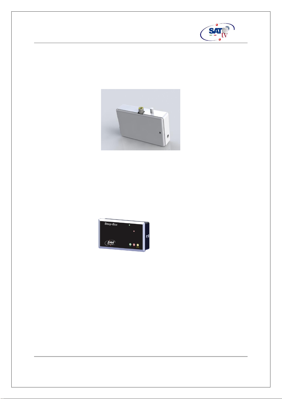
System Components
Inside the boxyou will find:
Automatic Antenna SAT-TV 40 or 65 or 80 based on what
you purchased.
5 Meters Ethernet cable to
connect the Antenna and The
Beep Box.
SCART-SCART Cable with an extra audio
RCA out to be connected to the Beep Box.
Coaxial cable to connect the antenna to the SetTop Box.
‘User Manual’’ Automatic Satellite Antennas TECHNO-MEDIASRL
UMN_00094001 Rev 7
TECHNO-MEDIA SRL
7
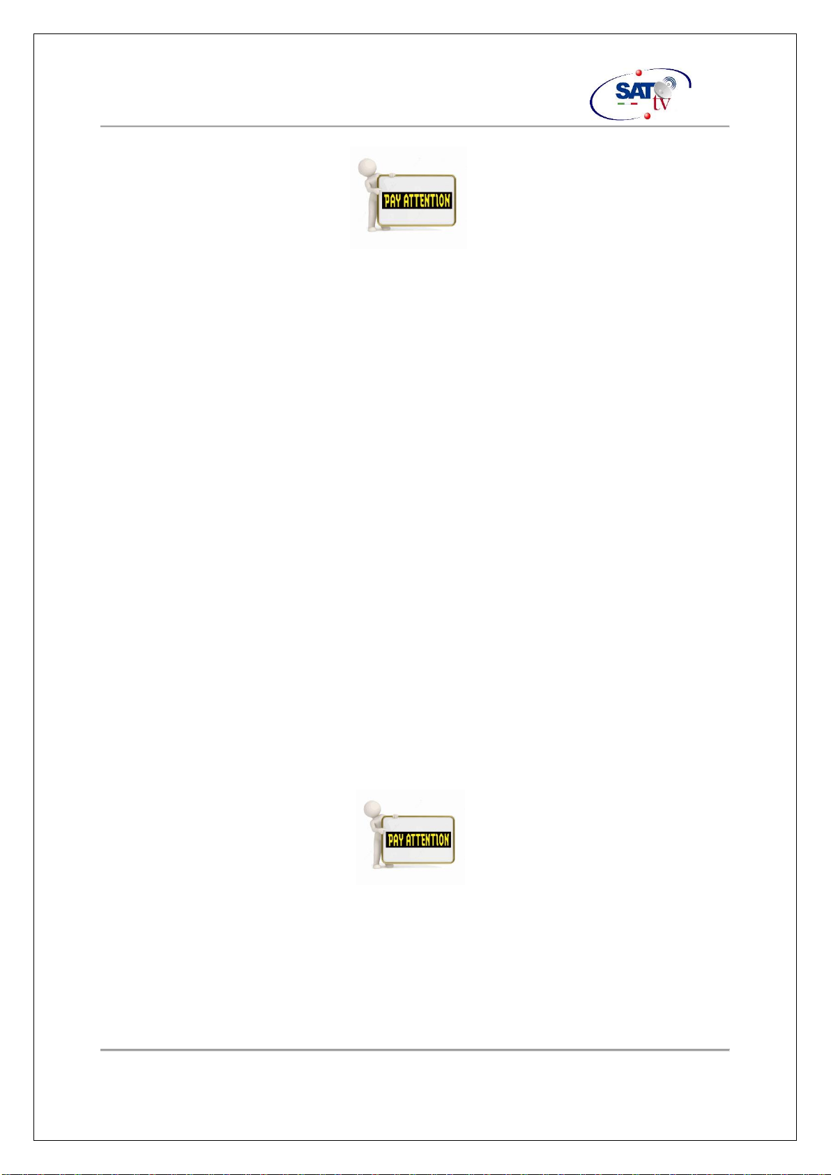
Depending on the version you purchased, you can have different type of power supply
box.
1) The Beep-Box 1. This unit allow to power up the antenna and close it using the
only one button available on the box.
The same button allow to program the type of Set Top Box used and the satellite
to be searched.
Please refer to the paragraph: HOW TO PROGRAM THE SET TOP BOX TYPE
2) Beep-Box 2
This one allow to switch off the antenna in order to easily download the new
settings for your Set Top Box.
‘User Manual’’ Automatic Satellite Antennas TECHNO-MEDIASRL
UMN_00094001 Rev 7
TECHNO-MEDIA SRL
8
Warranty
Both Electronics and Mechanical parts are covered for 2 years. **
** European Warranty.
Keep copy of the purchase document ( without this document we could not proceed
with a warranty repair).
Cost of the parts and works are covered by the warranty.
Shipment and risk for the transportation are customer costs.
Under a valid warranty we will proceed to renew the system with the latest
modification.
The replaced parts will not be returned.
The antenna warranty will be extended for an additional three (3) months and only on
the same defect.
If the validity of the warranty and in need of repair, bring the antenna to one of our
authorized service center. If there is no service center in your area, please send the
antenna in its original packaging at TECHNO-MEDIA srl. with a detailed explanation of
the defect. For added traceability, it is required to send an email to: info@techno-
media.it
‘User Manual’’ Automatic Satellite Antennas TECHNO-MEDIASRL
UMN_00094001 Rev 7
TECHNO-MEDIA SRL
9
Exclusions and termination of the warranty
Are expressly excluded from the warranty all those faults that are
attributable (at the discretion of the TECHNO-MEDIA Ltd.) to:
•Improper installation, misuse, neglect.
•Tampering or antenna opened by the user or unauthorized
personnel.
•Failures that are attributable to an incorrect antenna use.
•Use of non-original parts.
•Failures caused by adverse weather conditions such as lightning, hail and strong
wind.
•Failures caused by supply voltage or incorrect connections.
‘User Manual’’ Automatic Satellite Antennas TECHNO-MEDIASRL
UMN_00094001 Rev 7
TECHNO-MEDIA SRL
10
Installation
Safety Instruction for Installation
It is needed to pay attention to the following guidelines in order to avoid damage to the
people who will operate the installation.
Sincethe antenna will (in most cases)mounted on the roof of the vehicle
andthisbeinganoperationatriskoffallingfortheoperator,youwillneed
to take all preventive measures to avoid harm to people involved in the
assembly. It must also check that the capacity of the vehicle roof is able
to support the weight of the traderand tools needed during installation.
Be sure that:
1. Antenna and its parts are not powered during installation.
2. People involved does not suffer from Vertigo.
3. There is no risk to fall down from the roof or from the aids used to reach it.
4. Do not stand in a risky position where tools or material can fall down during the
installation.
‘User Manual’’ Automatic Satellite Antennas TECHNO-MEDIASRL
UMN_00094001 Rev 7
TECHNO-MEDIA SRL
11
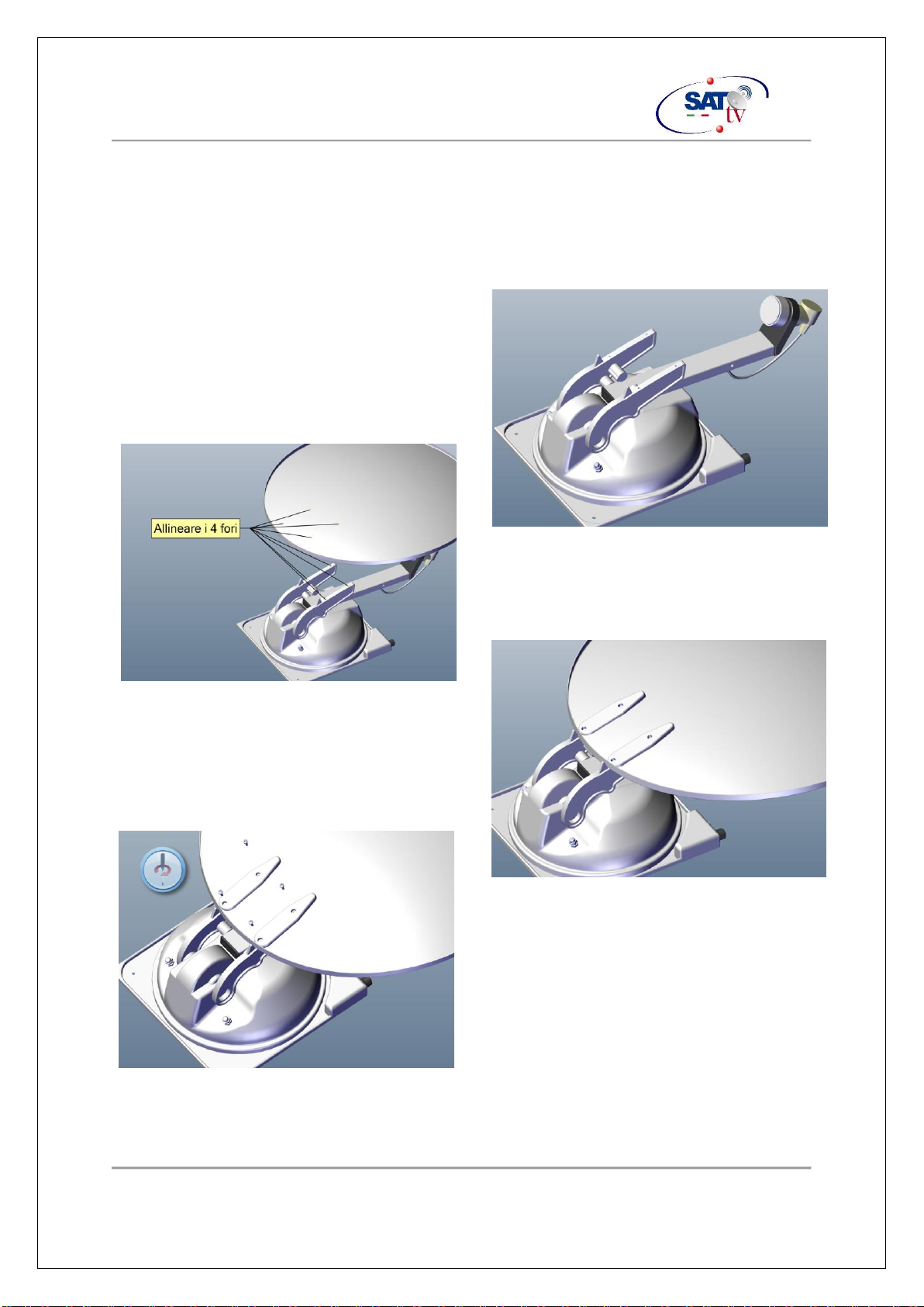
Dish Assembly
Dish is separated by the main body during shipment.
To install it a single Phillis screw driver is needed.
Screws are screwed on the main body and must be removed before installation.
Place the main body on a stable and flat
surface
Align the 4 holes on the Dish with the four
holes on the two support on the main body
Align the 2 plates with the dish and the main
body
Set the four screw firmly
‘User Manual’’ Automatic Satellite Antennas TECHNO-MEDIASRL
UMN_00094001 Rev 7
TECHNO-MEDIA SRL
12
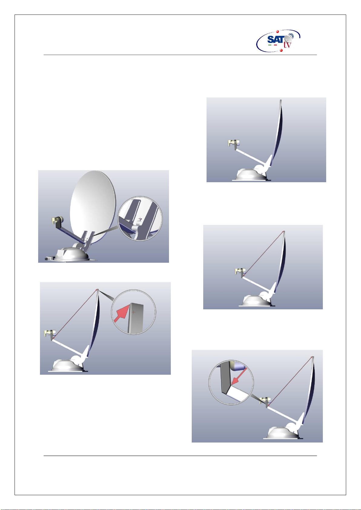
Arm Focus Tuning
In case of problems pointing a satellite, it is possible that a tuning of the arm/dish angle is
needed.
In case of that:
•Switch on the Set Top Box
•Switch On the Antenna pressing the ON
button
•Waituntiltheantennastartthehorizontal
rotation.
•Press the OFF button
With a screwdriver , turn the screw shown in
thepictureinordertoset thedistancebetween
the edge of the dish and the arm to 67 cm for
the dish of 65cm and 86 cm for the one of
80cm
Measure the distance from the hole close to the
edge of the dish
To the junction between the arm and the
plastic of the LNB handler.
Nowswitch ON again the Antenna and waitfor
the complete process.
‘User Manual’’ Automatic Satellite Antennas TECHNO-MEDIASRL
UMN_00094001 Rev 7
TECHNO-MEDIA SRL
13
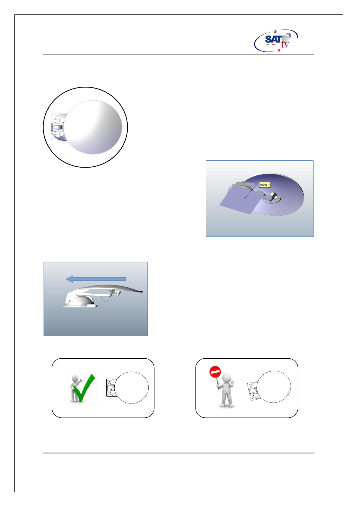
Antenna Installation
Verify that there is enough space on the roof of the vehicle
in order to allow the antenna movement. The antenna
always opens first vertically and then horizontally to allow
you to reduce the overall operating conditions but, in far
south regions, such as Morocco or North Africa, to point
the antenna of some satellites could tip very back, so it is
necessary that there are no objects that prevent its
rotation.
Consider a space of about 130 cm in diameter
around the antenna as shown.
Thoroughly clean the area identified for fitting and
removing all tracesof grease, dust and debris.
With a caulking gun, apply a uniform layer of
polyurethane adhesive on the baseplate of the
antenna body (Area 1). Refer to the operating instructions of the adhesive used. Use
adhesives compatible with the counter material (ABS) and the roof of your vehicle.
Then position the antenna in the above cleaned area
by paying attention to the direction. The arrow in the
figure indicates the direction of march of the vehicle.
Be sure that the antenna is parallelto the sides of
the vehicle.
‘User Manual’’ Automatic Satellite Antennas TECHNO-MEDIASRL
UMN_00094001 Rev 7
TECHNO-MEDIA SRL
14
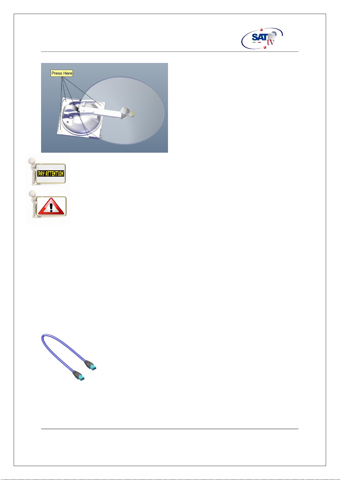
Press firmly on all four corners of the
aluminum plate and at the center of the cap
as indicated by the figure. Do not press
above the parabola to prevent warping it.
Thiswillirreparablydamagethemechanics.
Select a suitable adhesive to fix the baseplate ABS to your roof.
Follow the instructions from the manufacturer of the glue and in any case, let
itrestattheappropriatetemperature (seemanualglueinstructions)foratleast
24 hours before starting move the vehicle.
Passage of the cables
If it was notalready, make a hole for the passage of the two cablesrequiredto the antenna
operation.
Aftermaking the hole, fit the weatherproof box or the cable guide.
Run the two cables supplied in the kit if necessary with the help of an electrician's probe,
if you were to encounter resistance, DO NOT pull on the cables, you might run into the
cable breakand then the antenna malfunction. Such failure is not covered by warranty.
Ethernet cable 5 meters NOT cross
‘User Manual’’ Automatic Satellite Antennas TECHNO-MEDIASRL
UMN_00094001 Rev 7
TECHNO-MEDIA SRL
15
Antenna Coaxial cable 5 meters
Leave a sufficient cable length between the cable
guide and the antenna so you can reach the
connectors on the antenna connection body
without bending too close or keeping in tension
cables.
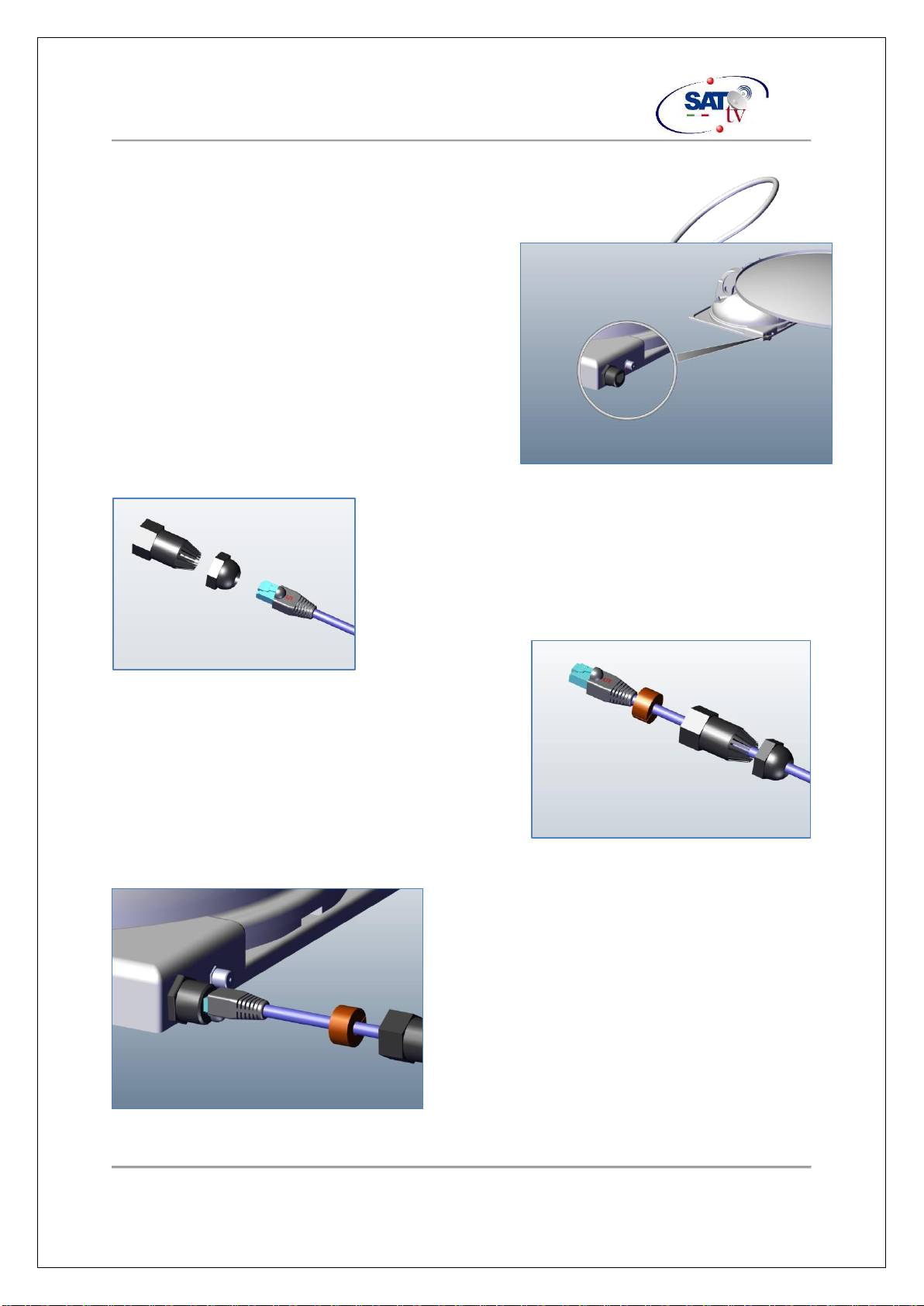
If not already assembled, install the seal and plastic cap
on the end of the Ethernet cable which isthen connected
to the antenna:
First plug the Ethernet cable into the side of the
guard as shown in the figure, first the rear and then
plug in the casing front.
Oncethecableisintothetwoparts,opentherubber
gasket provided and let it fit around the ethernet
cable.
Connect the RJ45 connector of the Ethernet
cable to the antenna connector, as shown in the
figure,insert theconnectoruntiltheretainingtab
does not Click
‘User Manual’’ Automatic Satellite Antennas TECHNO-MEDIASRL
UMN_00094001 Rev 7
TECHNO-MEDIA SRL
16
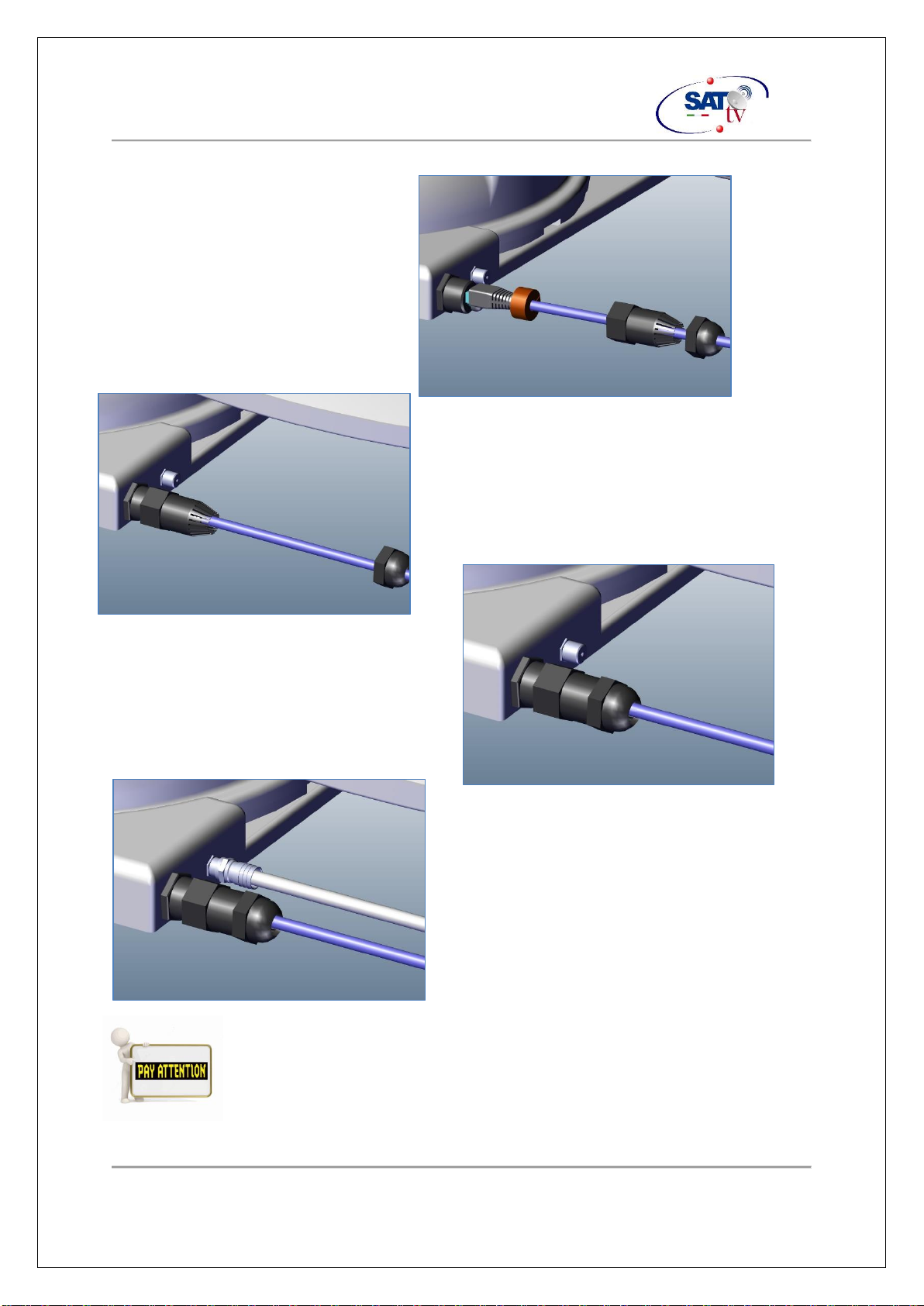
Move the seal close to the connector
Screw the connectorbody as shown in the
figure. Perform the operation carefully avoiding
to turn the other party on the dome. Do this by
hand without the use of tools, it is not
necessary to tighten too hard.
Screw the last part on the body of the
connector so that the gasket is contained
inside avoiding infiltrations of water. Do
this byhand without the aid of tools, it
is not necessaryto tighten too hard
Proceed at this point to the antenna cable
connection. Be careful not to rotate the
antenna connector on the body.
At this point the antenna installation will proceed in the vehicle. Had it not
been executed yet, be sure to fully sealed waterproof box or previously
mounted cable guide.

‘User Manual’’ Automatic Satellite Antennas TECHNO-MEDIASRL
UMN_00094001 Rev 7
TECHNO-MEDIA SRL
17
Installation of the control Box Beep Box Version 1
The installation of BeepBox 1 is very simple, there are only three wires that must be
connected:
•Power (Red and BlackWires)
•Ignition KEY power (YellowWire)
•Audio Signal from Set Top Box
1. Connect the RED WIRE to +12V of the Battery
2. Connect the BLACK WIRE to the negative of the battery or to the vehicle chassy
3. Connect the YELLOW WIRE to a 12V line which is powered only when ignition
key is turned or the vehicle is ON.
4. Keep the BeepBox in an accessible position.
Cavo
Ethernet.
Cavo
Antenna
Alim.
Principale
Beeper e
Fusibile
Chiusura
Sotto
Chiave

‘User Manual’’ Automatic Satellite Antennas TECHNO-MEDIASRL
UMN_00094001 Rev 7
TECHNO-MEDIA SRL
18
Installation of the BeepBox Version 2
The control and power supply box supplies
power to the antenna when you press the ON
button or when the vehicle is set in motion. It
allows you to close the antenna andto program
the type of decoder used.
Switching ON is delayed either pressing the ON
button or turning on the vehicle.
Install the Beep-Box leaving adequate ventilation to prevent electronics
failures.
Electrical Connections
Afteridentifying thepositionand setthe controller to the wall, proceed to connectingallthe
wires of the same as shown below:
Plug the RJ45 connector from the antenna on
theroofofthevehicle initsconnector,asshown
in figure until you hear the click of the retention
clips.
TaketheSCART-SCARTcable**fromthepackage
and connect the RCA connector to its connector on
the controller. Refer to the figure on the side
‘User Manual’’ Automatic Satellite Antennas TECHNO-MEDIASRL
UMN_00094001 Rev 7
TECHNO-MEDIA SRL
19
At this point you can proceed to the connectionof the power cables.
Even if the voltages involved are quite low, pay attention to avoid shorts
and invert connections.
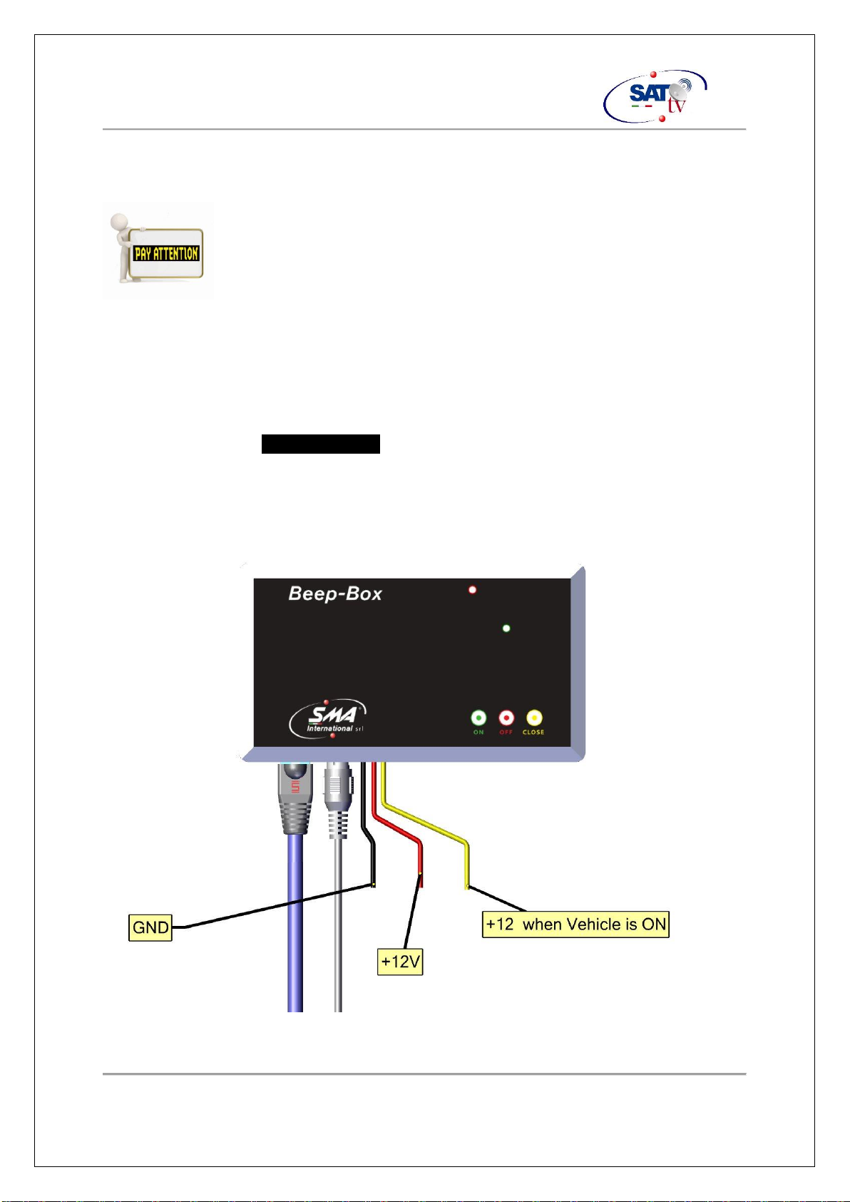
BeepBox with preassembled Wires
1. Connect the BLACK WIRE to the negative of the battery or to the vehicle chassy
2. Connect the RED WIRE to +12V of the Battery.
3. Connect the YELLOW WIRE to a 12V line which is powered only when ignition
key is turned or the vehicle is ON.
Refer to the belowpicture

‘User Manual’’ Automatic Satellite Antennas TECHNO-MEDIASRL
UMN_00094001 Rev 7
TECHNO-MEDIA SRL
20
BeepBox with FastOn connectors
In case of BeepBox with FastOn connection, asshown in the following picture, proceed to
connect power as indicated below:
1. Connect the BLACK WIRE coming from the negative of the battery to the Left
FastOn
2. Connect the RED WIRE coming from +12V of the Battery to the center FastOn
3. Connect the YELLOW WIRE which came from a12V line which is powered only
when ignition key is turned or the vehicle is ON to the Right FastOn.
This manual suits for next models
2
Table of contents
Popular Antenna manuals by other brands


Directive Systems & Engineering
Directive Systems & Engineering DSE1445LYA manual

Garmin
Garmin GMR 430 XHD3 Series installation instructions

CommScope
CommScope CMAX-DM20 installation guide

Wilson Electronics
Wilson Electronics 301119 installation guide

Steren
Steren ANT-9029 instruction manual

Leica
Leica Zeno FLX100 user manual

Travel Vision
Travel Vision R7 80 user manual

Winegard
Winegard SquareShooter HDTV2 SS-2000 user manual

Jonsa
Jonsa AKUY13 installation instructions

Oehlbach
Oehlbach Scope Vision Outdoor User's manual & warranty information

CUSHCRAFT
CUSHCRAFT LFA-2M16EL instruction manual

Tranzeo Wireless Technologies
Tranzeo Wireless Technologies TR-2000 manual