TECHNOALPIN M 20 AT User manual

2005
M
20 AT
USER MANUAL

TechnoAlpin M20
- 1 -
INDEX
1. AUTOMATIC OPERATION..............................................................................................2
1.1 AUTOMATIC REGULATION....................................................................................................................................................3
1.2 SERVICE CONSOLE FOR THE AUTOMATIC SNOW MACHINE.....................................................................................................5
2.0 KEYBOARD ………………………………..………………………………….……..……....6
2. OPERATION OF DISPLAYS, DIFFERENT MENUS AND VARIOUS LEVELS........................……….............…6
2.2 FUNCTION OF THE KEYS ……………………………………………………………….….....…..7
3.0 AUTOMATIC CONTROL ……………………………………………………………….…..8
3.1 THE SENSOR SET....................................................................................………................8
3.2 THE CONTROL UNIT PU-080- AND PU-79-P KEYBOARD ……………………….…..……………………8
4.0 WHAT A LEVEL IS ……..............................................................................………….9
5.0 LEVEL 1……………………………………………………………………..……….………10
5.1 STARTING THE M20 SNOW MACHINE.......................................................................….………11
5.2 STARTING AND MONITORING THE M20 SNOW MACHINES FROM DATA FIELD “STATUS”……………………15
6.0 LEVEL 2………………………………………………………………..……………………18
6.1 SETTING THE SNOW QUALITY ………………………………………………………..……….....19
6.2 SETTING THE WATER PRESSURE ……………………………………..………………………….20
6.3 SETTING THE AUTOMATIC START …………………………………….…………………………..20
6.4 SETTING THE HUMID BULB TEMPERATURE …………………………………………………..…….21
6.5 SETTING THE SPOTLIGHT ………………………………………………………………………..22
6.6 SETTING THE HIGH ANGLE …………………………………………………………………….…22
6.7 SETTING THE SWING ANGLE ………………………………………………………………..…....23
6.8 SETTING THE SHAFT NUMBER ……………………………………………………………….……24
7.0 LEVEL 3……………… ………………………………………..…………….……..….…24
7.1 CHOICE OF LANGUAGES ……………………...………………………..………..……..……….25
7.2 MODIFYING THE E2PROM VALUE…………………………………………….……….…..……….25
8.0 MANUAL OPERATION ……………………………………………………………….……26
8.1 MANUAL START FOR THE M20 SNOW MACHINE…….…………………………..………….………….26
8.2 OPERATION ……………………………………..……………………….…………………...27
8.3 STOPPING………………………………………………………………………….….………29
9.0 ERROR MESSAGES ..................... ............…….................................29
TechnoAlpin M20
- 2 -
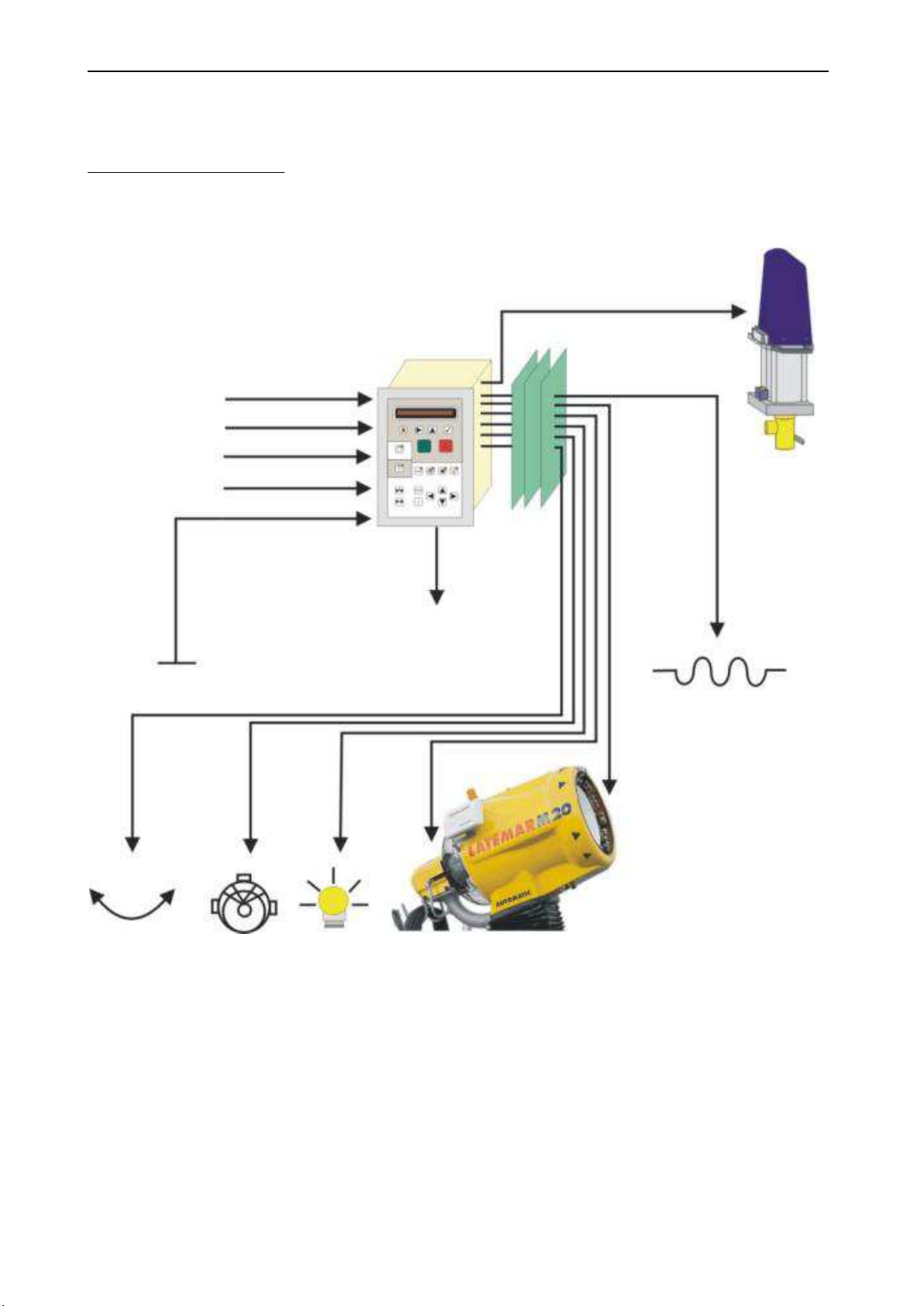
1. AUTOMATIC OPERATION
Automatic operation has been developed to minimize the operating expenditure. Running and stop phase will be
regulated automatically and during operation the snow machine sets itself according to the environmental
conditions.
Block scheme:
Swinging
Compress.
Spotlight
Air temp.
Atass
Humidity
Water temp
Wat.press.
Shaft num.
Turbine
keyboard
Valve card 1
Valve card 2
Power card
Hydromat
Heating
Control
un
TechnoAlpin M20
- 3 -
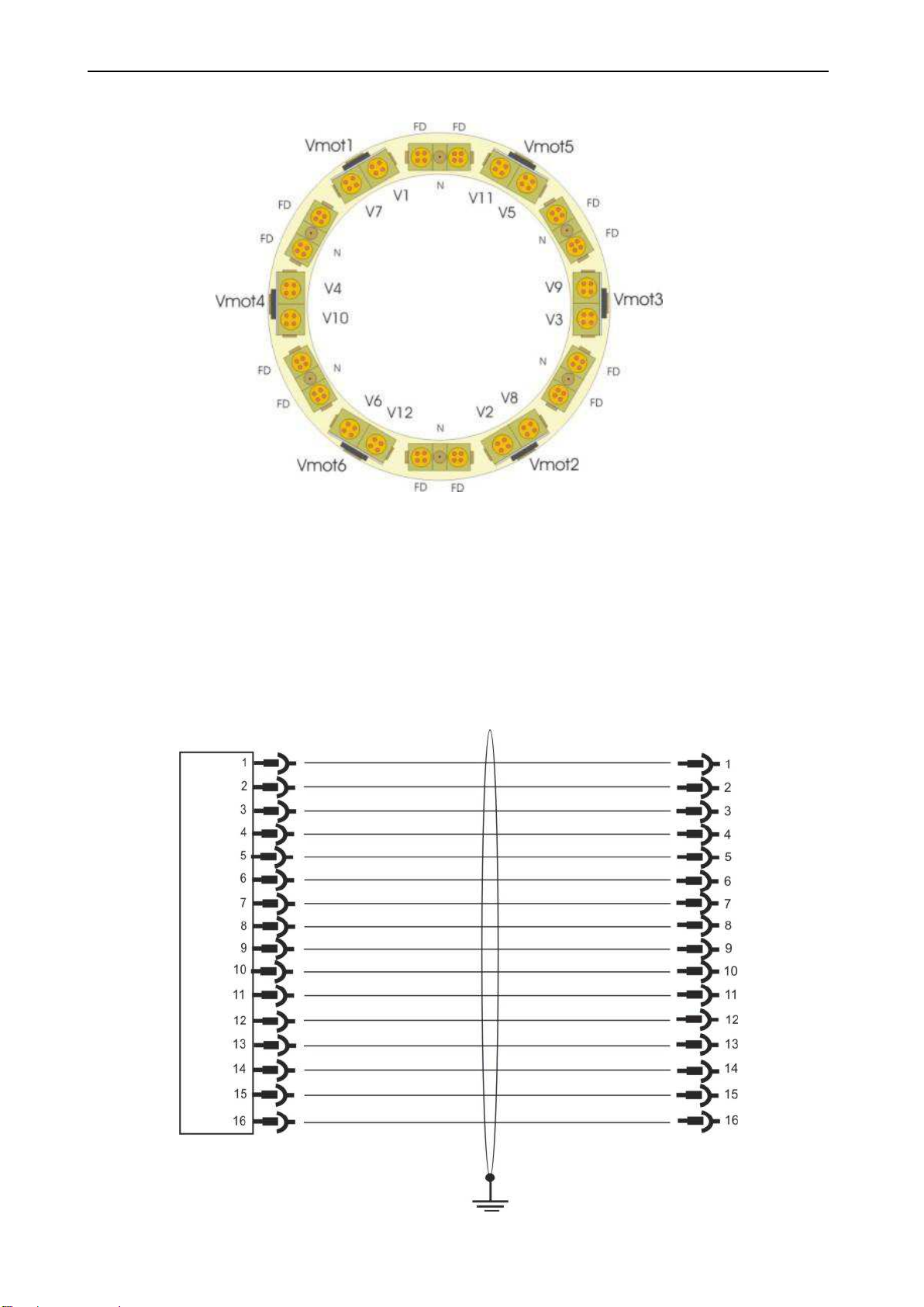
THE JET RINGS
On the M20 jet ring you find (viewed from the front):
o12 fixed jets (FJ)
o6 nucleators (N)
o12 switchable jets (numbered V1….V12)
o6 valve motors (numbered Vmot1…..Vmot6)
1.1 AUTOMATIC REGULATION
Automatic regulation is accomplished through the sensor set, the control unit and the valve cards. The snow
machine sets itself according to the given environmental conditions to produce the required snow quality. If an
automatic hydrant of the Hydromat SE is installed, the snow machine can also independently set the water
pressure to the required operating pressure.
Automatic Hydrant recognition:
24 V extern
Automatic Hydrant present
Extern Start (if available)
Extern Stop (if available)
Hydromat 200 present
Hydrant on
Hydrant off
24 V Shaft recognition
white/green (3)
Shaft recognition canal 1
yellow/brown (2)
RS 485 yellow
red(1)
RS 485 green
RS 485 brown
RS 485 white
r
E-motor present
Shaft recognition
channel 2
0 V extern
white/yellow (4)
red/green (7)
pink (8)
blue (9)
yellow (10)
brown (12)
green (11)
white (13)
grey (14)
violet(15)
black(16)
grey/pink (5)
brown/green (6)

TechnoAlpin M20
- 4 -
Circuit diagram
X1
X1
Plug to
Hydromat
16 pin
10x1,5mm² 10x1,5mm ² 4x(2x1mm²) 4x(2x1mm ²)
4x(2x1mm²) shildet c able
4x(2x1mm²) shildet c able
power cable 4x25-50mm²
heating2x1m m²
HYDROMAT4X15MM²
RS485
RS485
pro tec tion 4x63A
FI 4x63A 3 00m A
hydrom at protec tion PKZMO_16A
heating 16A
1234567 8 910
1
2
3
4
5
6
7
8
9
10
11
12
13
14
15
16
ca ble 10x1,5mm²
ca ble 10x1,5mm ²
24V extern
hydrom at present
start extern
stop extern
hydrom at 2000 present
hydrant open
hydrant closed
pit recognition+ 1
p it re c og nition-1
1
1
blue
blue
2
2
blue
blue
0V extern
p it re c ognition-2
E-Motor for manuel
hydrant p resent
16 PIN
PLUG
MANUAL
+
3
blue
4
blue
RS485
RS485
RS485
RS485
RS 485
RS 485
RS485
RS485
21
p it re c og nition
1-50
51-200
data c able
RS-485
4x(2x1mm ²)
data cable
RS-485
4x(2x1mm ²)

TechnoAlpin M20
- 5 -
Hydromat SE:
The Hydromat SE is an automatic Hydrant with hydraulic / electro-mechanical control, which is run automatically
from the snow cannon. The snow cannon reads and compares the given parameters and operates the
opening/closing of the hydrants.
The Hydromat SE is equipped with an electrical keyboard for manual operation and can, if necessary, be directly
mechanically operated on the equipment.
1.2 THE SERVICE CONSOLE OF THE AUTOMATIC SNOW MACHINE
The operating console represents the man–machine –interface of the snow machine. It shows us a display and a
row of service keys. The key group is divided into two areas: the upper gray area is where we find automatic
operation and the lower white area is where we find the manual operation.
KEYBOARD

TechnoAlpin M20
- 6 -
Auto
_ _ _ 0
0.0 bar
Off
The snow machine
measures in this case 0.0
bar water pressure
Operational condition; the
snow machine is switched
off.
The snow machine is
set on automatic
operation, it is
switched off.
H.....Heating turned on
K.....Compressor turned on
T.....Turbine turned on
2.0 THE KEYBOARD
On the M20 snow machine with tower the keyboard is integrated along with the control unit
in the switch box, however the keyboard is fixed on under the tower for machine service. It
is linked to the control unit with a CANbus.
The keyboard has a display with 2x20 symbols and 20 keys.
IMPORTANT: Next to the slave key you will find an emergency off key, to close off the
machine in emergencies.
It is divided into 2 operational levels: the upper gray part for automatic operation, the lower
white part for manual operation.
2.1 OPERATION OF DISPLAY, DIFFERENT MENUS AND VARIOUS LEVELS
The display has 2x20 symbols. The first line of the display shows the operational situation
(it says whether the snow machine runs automatic mode or manual), it describes the
measured environmental conditions and the calculated values (humid bulb temperature).
The second line serves for the description of the environmental parameters, the calculated
values and for the task of error reports.
The environmental parameters are the following: air temperature, water pressure, relative
humidity, water temperature. The parameters displayed are measured values.
Calculated values are: humid bulb temperature and water capacity, where the displayed
values can slightly differ from the real values.
The 3 lines show
the operational
condition of the
equipment, left to right.
CONTROL
KEYS
Display
KEYS FOR AUTOMATIC
OPERATION
KEYS FOR
MANUAL
OPERATION
TechnoAlpin M20
- 7 -
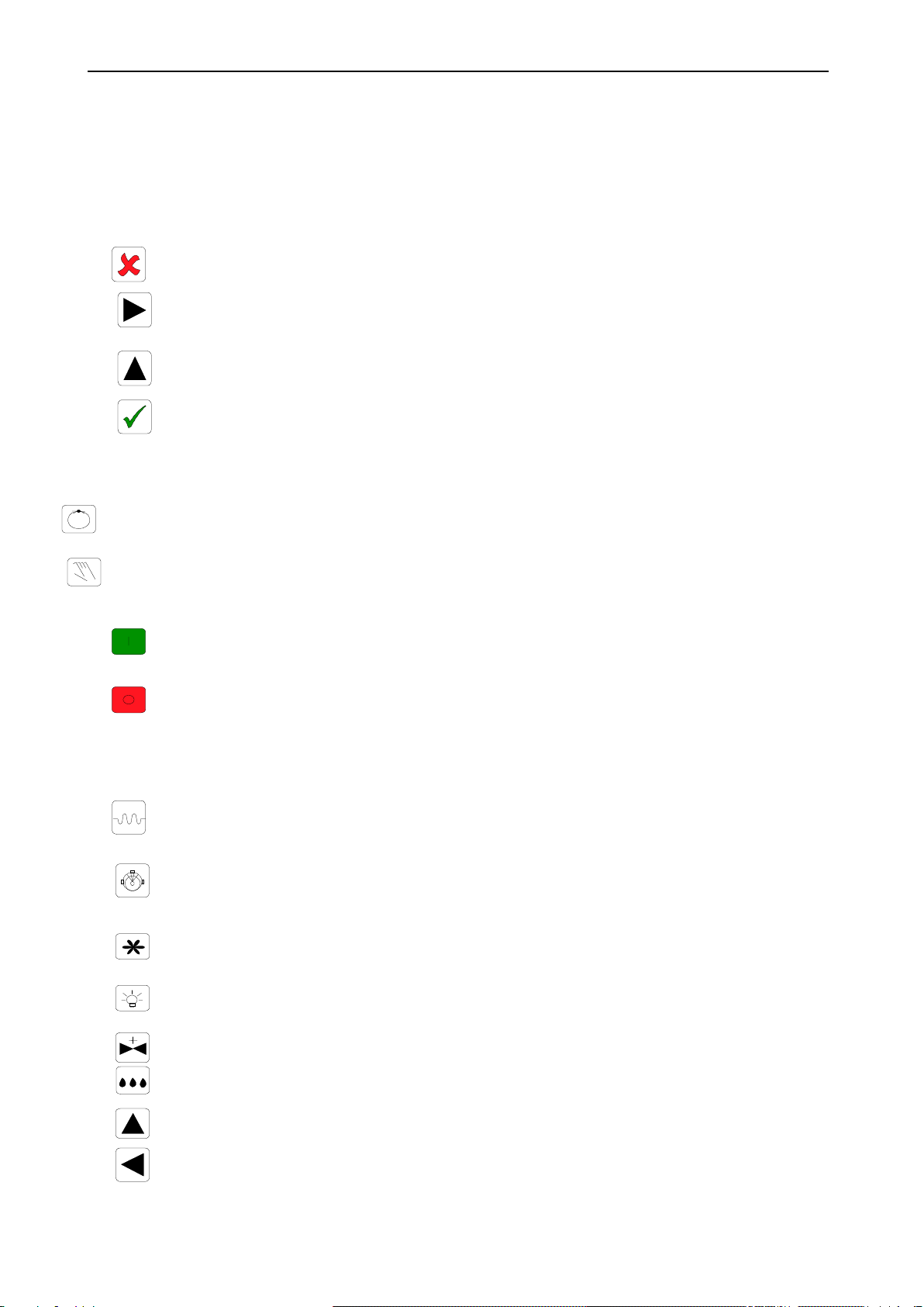
2.2 FUNCTION OF THE KEYS
To control the display, the different menus and different levels there are 4 keys at your disposal: ESC, DOWN, UP
and ENTER.
The ESC key serves for being able to move from one level to the preceding one. If pressed repeatedly,
it acts to reach level 1.Moreover this key is used for leaving a menu (in the case of a level having more
than one menu) .
The DOWN key is used to leaf backwards through the menu, or to lessen values (to number off).
The UP is used to further leaf through the menu, or to increase value (enumerate).
The ENTER key will be used to move from level 1 to level 2 (and further), or to confirm changes. A
menu can be chosen with the key too.
KEYS TO SWITCH BETWEEN AUTOMATIC OPERATION AND MANUAL.
Key for automatic operation: after pressing this key the snow machine runs in automatic.
Key for manual operation: after using this key the snow machine runs in manual.
On and off keys:
Keys for manual operation:
Key for turning on and off Turbine in manual operation
START- key for automatic operation
STOP –key for automatic operation
Key for turning on and off heating in manual operation
Key for turning on and off compressor in manual operation
Key for turning on and off lighting in manual operation
OPENING OF THE HYDRANTS
OPENING OF THE VALVES
Turbine upwards
Turn to the left

TechnoAlpin M20
- 8 -
3. AUTOMATIC REGULATION
Automatic regulation is accomplished through the sensor set, the control unit and the valve cards. The snow
machine sets itself according to the given environmental conditions to produce the required quality in snow.
If an automatic Hydrant of the type E-Motor, Hydromat or Hydromat 2000 is installed, the snow machine can also
set the water pressure independently to a required operation pressure.
3.1 THE SENSOR SET
The sensor set serves for fixing the humid bulb temperature and possesses 2 sensors, which can measure the air
temperature from –30°C to +30°C and the relative air humidity from 0 to 100%. The output measurement signal
ranges between 4 and 20 mA .
The sensors are installed in a measuring station directly on the snow machine and deliver their values directly to
the control unit, which then in turn calculates the humid bulb temperature. This humid bulb temperature forms the
basis for the snow production in the automatic operation.
Besides this, the water temperature and water pressure are measured on the jet ring. The values serve to
influence the condition of the jets and to regulate the water quantity. All sensors send their information to the
control unit, which works on the data.
The water pressure will be measured from 0 to 60 bar and converted into a measurement signal between 4 and
20 mA; the water temperature will be measured from –10°C to +30°C, and converted into a signal between 4 and
20 mA.
3.2 THE PU-080 CONTROL UNIT AND PU-79-P KEYBOARD
With the M20 AT snow machine control unit and keyboard are 2 units, which are linked through a CANbus. The
control unit is a programmable controller unit and has the functions of reading data, storing data and working on
read analog value. The control unit, to which the different sensors are connected, calculates the energy content of
the air. This calculated value will be corrected with the water pressure. A further correction will be made based on
the required snow quality. The result of the calculations results in the required amount of water leading to the
correct opening of the jets. As well as this, the control unit continually supervises the proper function of the M20.
The control unit receives the environmental data from the sensors and the set parameters from the keyboard.
Each switching process is checked and in the case of an error the corresponding error report appears on the
display and if necessary the machine will be halted. The control unit has 16 digital inputs/outputs, 6 further analog
inputs and 2 serial ports:
The RS 422-interface works in the (ATASS) network and the RS 232-interface serves for serial communication
with a PC.
Closing of hydrants
Closing of valves
Turbine downwards
Turn to the right

TechnoAlpin M20
- 9 -
4. WHAT IS A LEVEL?
A level brings together various menus with their data, such as the level for the memory read analogue values. The
M20 Software is subdivided into 3 levels:
Level 1 is the main level and it concerns the operational condition and contains 7 data sets
Level 2 contains variable parameters: with a maximum of 9 data sets.
Level 3 contains 3 data sets: the version of the software, the choice of language and the E2prom
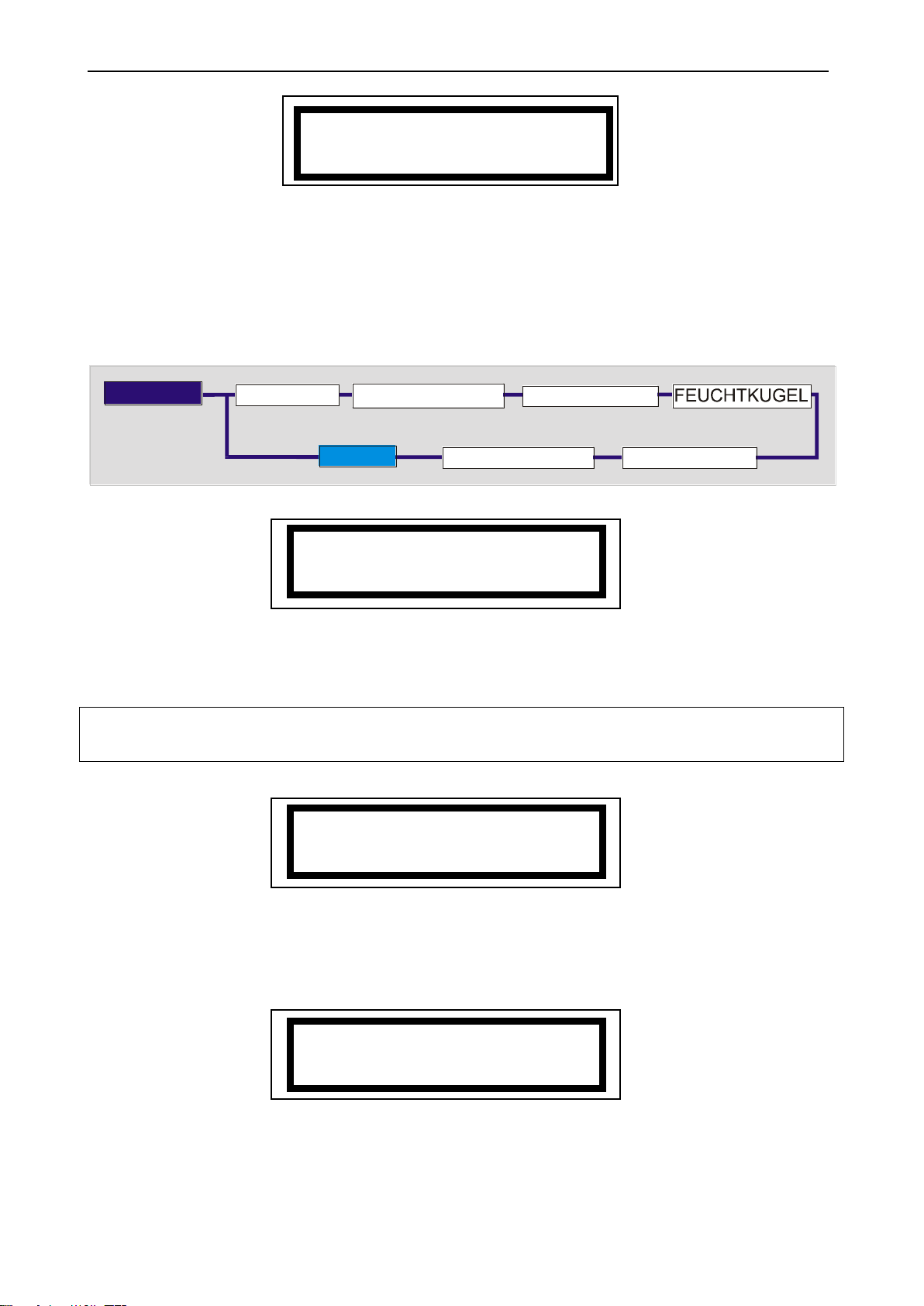
LEVEL 1 AIR TEMP WATER PRESSURE REL. HUMIDITY HUMID BULB TEMP.
STATUS WATER CAPACITY WATER TEMP.
LEVEL 2 SNOW QUALITY TARGET PRESSURE AUTOMATIC SNOW READY
SHAFT NUMBER SWING TARGET POS. VERTICAL LIGHT
LEVEL 3 SOFTWARE VERSION LANGUAGE
STORE E2PROM
EBENE 1 WASSERDRUCK REL FEUCHTE
STATUS WASSERDURCH WASSERTEMP
EBENE 2 SCHNEEQUALIT SOLLDRUCK AUTOMATIK
SOLLPOS. VERTIKAL LICHT
SCHNEIBEREIT.
SCHWENKEN
SCHACHTNUMMER
LUFTTEMP
EBENE 3 SOFTWARE VERS SPRACHE
SPEICH. E2PROM
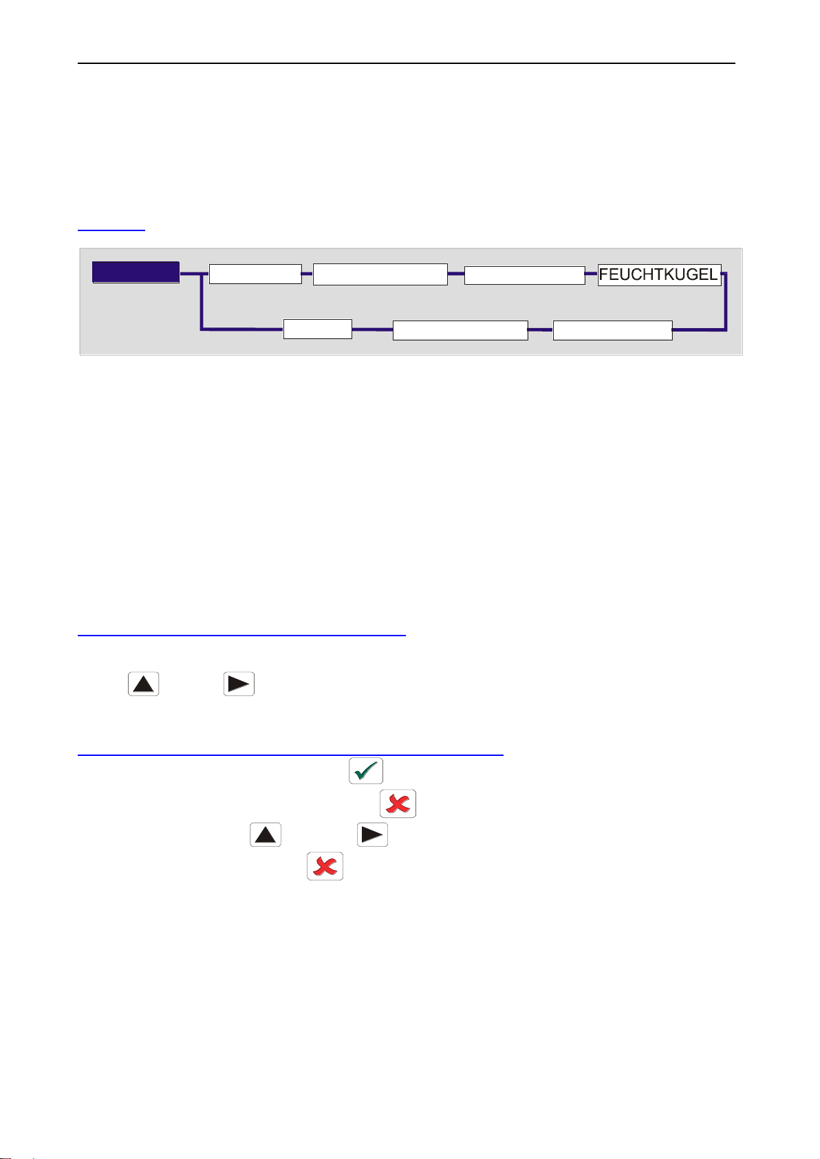
In the following part of the handbook the functions of different levels will be explained in detail. The heading line of
the page should be helpful for you in terms of understanding the levels and can look as follows:
EBENE 2 SCHNEEQUALIT SOLLDRUCK AUTOMATIK
SOLLPOS. VERTIKAL LICHT
SCHNEIBEREITSCHA
SCHWENKEN
SCHACHTNUMMER
TechnoAlpin M20
- 10 -
LEVEL 2 SNOW QUALITY TARGET PRESSURE AUTOMATIC SNOW READINESS
SHAFT NUMBER SWING TARGET POS. VERTICAL LIGHT
Here we are speaking about the second level and in detail about the setting of snow quality.
5. LEVEL 1
EBENE 1 WASSERDRUCK REL FEUCHTE
STATUS WASSERDURCH WASSERTEMP
LUFTTEMP
LEVEL 1 AIR TEMP. WATER PRESSURE RELATIVE HUM. HUMID BULB TEMP.
STATUS WATER CAPACITY WATER TEMP.
Level 1 is the operation level and contains 7 settings:
Air temperature (+30..-30°C)
Water pressure (10...40 bar)
Relative air humidity (0%....100%)
Humid bulb temperature (0...-10 °C)
Water temperature (-10...+30 °C)
Water capacity (0...15 l/s)
Status (Status of the snow machines)
The data in level 1 cannot be changed, these serve only as information.
HOW CAN I MOVE AROUND IN LEVEL 1 ?
To change from one data setting to another in level 1
the UP and DOWN keys may be used.
HOW DO I MOVE FROM ONE LEVEL TO THE OTHER ?
To change to level 2 simply press the ENTER key.
To leave level 2 and to get back to level 1, the ESC key can be pressed.
To change to level 3, the UP and DOWN keys in level 2 must be pressed at the same time.
To leave level 3, simply press the ESC key.

TechnoAlpin M20
- 11 -
5.1 STARTING THE M20 SNOW MACHINE
EBENE 1 WASSERDRUCK REL FEUCHTE
STATUS WASSERDURCH WASSERTEMP
LUFTTEMP
LEVEL 1 AIR TEMP. WATER PRESSURE REL. HUM. HUMID BULB TEMP.
STATUS WATER CAPACITY WATER TEMP.
Before the snow machine is started up by an appropriately trained
technician, the following must be observed:
The current EC designated norms in terms of security mechanisms must be laid out in the working area. .
The snow machine must be solidly fixed to its site.
The hydraulic connections will have to be tested.
The electrical supply must be sound and all cables must be intact.
No unauthorized persons should be in the area surrounding the snow machine.
1. The electrical supply must be connected and the main switch must be on Position 1 (switched on).
A sign now appears on the display.
2. Connect the water supply to the snow machine.
Attention: Before starting the snow machine all the safety instructions must be read through and followed in a
precise manner.
ATTENTION:
Before starting you must be absolutely sure that the ventilator pipe is free
(intake- and power out area). The ventilator impeller wheel must be able
to freely turn and can in no case be iced over.
The snow machine can be started from each data field of level 1.
(also valid for level 2)
Bring the main switch on to position 1(turned on). The following data is seen on the display. (illustration 1):
illustration 1
Auto shows that the snow machine is in automatic operation (default).
The operation condition will be shown on the three lines _ _ _ : the heating (appears as H on the first
line, when it is switched on), the compressor (appears as C on the second line when switched on)
and the turbine (T on the third line, when switched on).
Auto - 30 °C
_ _ _ 0 Off

TechnoAlpin M20
- 12 -
0 corresponds to the number of open switchable jets. At the start no jets are open, the snow machine
starts only with fixed jets. In the best of situations up to 10 jets may be opened.
Off corresponds to the operation situation of the snow machine in its opening stage.
-30°C corresponds to a meteorological value, that will be shown on the second level after applying
the UP or Down keys (in this case the air temperature appears).
EBENE 1 WASSERDRUCK REL FEUCHTE
STATUS WASSERDURCH WASSERTEMP
LUFTTEMP
LEVEL 1 AIR TEMP. WATER PRESS. REL. HUMIDITY HUMID BULB
STATUS WATER CAPACITY WATER TEMP.
Bild 2
illustration 2
If the machine is to be started:
Press the START key
ATTENTION
During the starting phase the light is switched on.
In display the following is shown (illustration 3):
Bild 3
illustration 3
The letter H on the line shows that the heating is switched on.
The ***START symbol means that the machine has been started.
The value –30°C shows the air temperature, if you want to see the description of the shown value (naturally
without switching off the machine) the UP
or DOWN key can be pressed. The following appears on the
display (illustration 4):
Auto - 30 °C
_ _ _ 0 Air temp.
fttemp
Auto - 30 °C
H _ _ 0 *** START ***

TechnoAlpin M20
- 13 -
iIlustration 4
INFORMATION
If the words: START, STOP, READY!, WAIT... and OFF appear on the display the UP
or DOWN
keys can be pressed, to see the description of the shown value in the upper lines.
After the starting phase, for which the heating will always remain switched on, the heating will be switched on and
off for variable time periods, depending on the air temperature.
At the same time the snow machine starts positioning. The turbine swings downwards, to the end switch, then it
goes to the set position (in the case of a built-in electric motor).
In the meantime the compressor will be switched on, its warm running time depends on the measured air
temperature.
On the display the letter Kappears on the second line position as will be seen in illustration 5:
EBENE 1 WASSERDRUCK REL FEUCHTE
STATUS WASSERDURCH WASSERTEMP
LUFTTEMP
LEVEL 1 AIR TEMP. WATER PRESSURE REL. HUMIDITY HUMID BULB TEMP.
STATUS WATER CAPACITY WATER TEMP
Bild 5
Illustration 5
After the warm running time of the compressor is completed, the valve test will be carried out. If the valve
test is successfully completed, the swinging operation begins (if a swing width is set). Then the turbine may
be brought into use, the letter T appearing on the third line position. ( illustration 6).
Bild 6
Illustration 6
Finally the hydrant will be opened.
ATTENTION (in the case of an automatic hydrant available)!
When a minimum pressure of 8 bar on the jets is not reached within a short time span, then a corresponding error
report will be given and the machine will be halted.
If a smart hydrant such as Hydromat SE, Hydromat 2000 or E-Motor is connected to the snow machine, the
machine will open the hydrant automatically.
Auto - 30 °C
H _ _ 0 Air temp.
Auto - 30 °C
H K _ 0 Air temp.
Auto - 30 °C
H K T 0 Air temp,

TechnoAlpin M20
- 14 -
IMPORTANT
In the case of manual hydrant installation, then this must be opened within 60 minutes.
OPERATION:
Now the snow machine is in operation.
During this phase the following should be considered:
The water pressure will be regulated by means of opening and closing the hydrant.
The switchable jets will be opened and closed depending on the humid bulb temperature, the water
temperature and the water pressure.
Snow control: check the quality of the snow produced where it mostly collects.
There is the possibility to change the set snow quality.
Continually supervise the correct running of the machine, even when it is in automatic mode.
ATTENTION
When the machine is in operation, do not stand in front or at the back of the
running turbine!
At all times (operation, running phase, stop phase,.... the machine):
EBENE 1 WASSERDRUCK REL FEUCHTE
STATUS WASSERDURCH WASSERTEMP
LUFTTEMP
LEVEL 1 AIR TEMP. WATER PRESSURE REL. HUMIDITY HUMID BULB TEMP.
STATUS WATER PRESSURE WATER TEMP.
All data can be seen in level 1. The UP and DOWN keys may be used.
Some parameters can be set in level 2, be altered (as will be explained in the following section). The machine sets
itself automatically on the newly given parameters.
You may change to level 3 and alter parameters (as will be explained in the following section).
THE STOP PHASE
Pressing the STOP key , the following appears on the display :

TechnoAlpin M20
- 15 -
Illus. 7
You see from the display that the machine is in the stop phase(***STOP*** ) but the turbine (T), the compressor
(C) and the heating are (H) still in operation, these will be automatically switched off at a given moment.
In the case of installation of a smart hydrant such as Hydromat SE type, Hydromat 2000 or E-Motor, then there will
be automatic closure by the snow machine.
IMPORTANT
In the case of manual hydrant installation, then closure must follow within 60 minutes by hand.
As soon as the machine is turned off, the water hose must be separated from the machine and emptied.
ATTENTION
In the case of an apparent machine error, the warning light will flash.
5.2 STARTING AND SUPERVISING THE M20 SNOW MACHINE WITH THE “STATUS” DATA FIELD
EBENE 1 WASSERDRUCK REL FEUCHTE
STATUS WASSERDURCH WASSERTEMP
LUFTTEMP
LEVEL 1 AIR TEMP. WATER PRESSURE REL. HUMIDITY HUMID BULB TEMP.
STATUS WATER CAPACITY WATER TEMP.
In order to follow each step that the machine carries out in start and stop phase, simply go to the “Status” field on
level 1.
If the machine is actually switched off, you can gather the following from the Status:
Initially the snow machine is switched off: (illustration 8)
Bild 8
Illustration 8
After the automatic start has been set, and the environmental conditions allow snow production , “READY”
appears on the display (illustration 9):
Auto - 30 °C
H K T 0 ***STOP***
Auto Status
_ _ _ 0 cannon off
TechnoAlpin M20
- 16 -
Bild 24
illustration 9
Now simply press the START key , to set the snow machine in motion.
If the automatic start is active and the START key pressed before “Ready” is shown, the cannon will not
start. The report Wait... (illustration 10) appears. The cannon then waits until the environmental conditions set on
to “snow readiness”. Then the machine can start by itself.
illustration 10
After the above-described start phase data, you here see the necessary indications:
After pressing the START key the heating will be switched on and shown on the display (illustration 11):
Bild 9
Illus. 11
After the startup phase, in which the heating always remains on, the heating will constantly be switched on and off
for longer or shorter periods depending on the air temperature.
In the case that the snow machine is fitted with a motor for vertical adjustment, the snow machine begins
positioning. The turbine swings downwards, up to the end switch, then it positions itself in the set position. See
display (illus. 12)
Illus. 12
If the machine has reached the set position, the following appears on the Display (Illus. 13)
Auto Status
H _ _ 0 Positioning
Auto Status
H _ _ 0 Start
Auto Status
_ _ _ 0 Ready !
Auto Status
_ _ _ 0 Wait...
TechnoAlpin M20
- 17 -
Illus. 13
In the case that the snow machine is not fitted with a motor for vertical setting (the hand crank will be used to bring
the snow machine into position) the word ‘start‘ remains on the display, see picture 11.
Then the compressor will be switched on, needing a warming up period, depending on the measured outside
temperature.
The following phase is planned for the valve test (illus. 14)
EBENE 1 WASSERDRUCK REL FEUCHTE
STATUS WASSERDURCH WASSERTEMP
LUFTTEMP
Bild 12
Illus. 14
The equipment now begins to swing, in the case that a swing width larger than 0 is set.
Then the turbine will start off and the hydrant will be opened, if an automatic hydrant is connected (illus 15).
In the case that only a manual hydrant has been installed, the snow machine waits for the opening by the user.
ATTENTION
In the case that the hand operated hydrant is not opened within 60 minutes, an error report appears on the display,
and the machine will be stopped.
illustration 15
As soon as the water pressure exceeds a fixed value, the snow machine is operationally ready. The following
appears on the display. (illustration 16):
illustration 16
Auto Status
H _ _ 0 Position OK
Auto Status
H K _ 0 Valve test
Auto Status
H K T 0 hydrant open
Auto Status
H K T 0 operation

TechnoAlpin M20
- 18 -
STOPPING THE M20 SNOW MACHINE FROM THE “STATUS” DATA FIELD
Also when stopping the snow machine, all steps that the machine is carrying out can be supervised from the
“Status” data field.
If the STOP key is pressed, the following appears on the display (illustration 15):
illustration 17
The next step is closing the valves and the hydrant. When an automatic hydrant has been installed, this will be
closed by the snow machine itself, otherwise the snow machine waits until the hydrant will be closed manually by
the user (illustration 16).
illustration 18
ATTENTION
When the manual hydrant has not been closed within a period of 60 minutes, then an error report appears on the
display and the machine keeps running, as long as the water pressure does not sink to under 2 bar
(The automatic hydrant needs a shorter switch off time.)
With the closing of the hydrants, all valves will be closed at the same time. In the case of jet ring pressure of more
than 2 bar, all valves will be opened, so as to improve emptying.
After this phase the turbine will be switched off (illustration 19).
Illus. 19
The compressor will be immediately stopped after the switching off of the turbine.
As soon as the compressor is switched off, the turbine pipe goes to the vertical position. The remaining
water can then flow from the jet ring and icing over will be avoided.
(illus. 20).
Illus. 20
Auto Status
H _ _ 0 Cannon on_off
Auto Status
H K T 0 ***STOP***
Auto Status
H K T 0 hydrant closed
Auto Status
H K _ 0 turbine off

TechnoAlpin M20
- 19 -
The turbine pipe will then go into the vertical basic position (illus. 21).
Bild 19
Illus. 21
After this the machine has gone back to the basic position (start position), the heating will be switched off.
If the on phase has ended, the following appears on the display (illus. 22):
Illus. 22
6. LEVEL 2
EBENE 2 SCHNEEQUALIT SOLLDRUCK AUTOMATIK
SOLLPOS. VER LICHT
SCHNEIBEREIT
SCHWENKEN
SCHACHTNUMMER
Level 2 snow quality target pressure automatic snow readiness
Shaft no. swing target position vertical lightning
Level 2 is the menu for changeable parameters, it contains 8 settings:
Snow quality (1...9)
target pressure (10....40 bar)
Automatic operation (on/off)
Snow readiness
spotlight (on/off)
Vertical position (0...5)
Swing width (0....7)
Shaft number (1...255)
The parameters in level 2 can be changed and can be set to a required value.
The snow machine can also be switched on from level 2. The start process is the same as already described as in
level 1.
HOW CAN YOU MOVE AROUND IN LEVEL 2 ?
To change from one data field into the next in level 1, simply press UP or DOWN . When these keys
are pressed longer, you have the function to count values up and down faster.
HOW DO I MOVE FROM ONE LEVEL TO THE NEXT ?
To reach from level 1 to level 2, press the ENTER key.
Auto Status
H _ _ 0 Cannon mid
Auto Status
_ _ _ 0 Cannon off
Table of contents


