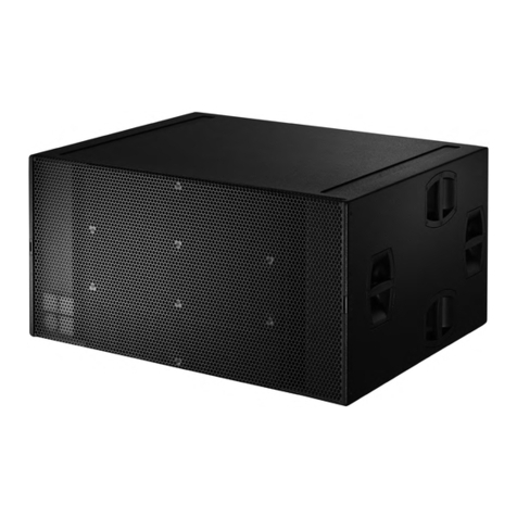
TECNARE Sub Series User manual

Keep these important operating instructions.
Check www.tecnare.com for updates.
Operation Manual
Compact Subwoofer
SW-118M
Sub-Series


SW-118M
Operation Manual
Subwoofer Series | rev.
2.00
2
General Information
Sw-118M Operation Manual
Ver.: 2.0_UK 11/2016
©EXEL ACOUSTICS SL; all right reserved
The information contained in this manual has been
carefully checked for accuracy, at the time of going to
press, however no guarantee is given with respect to
the correctness.
Exel Acoustics SL accepts no responsibility for any
errors or inaccuracies that may appear in this manual
or the products and software described in it. Technical
specifications, dimensions, weights and properties do
not represent guaranteed qualities. As manufacturers
we reserve the right to make alterations and
modifications within the framework of legal provisions,
as well as changes aimed at improving quality.
EXEL ACOUSTICS SL
CL Encinar, 282 – Pol. Ind. Monte Boyal
45950 Casarrubios del Monte (Toledo) Spain
Phone: (+34) 918 170 110 Fax:
e-mail: support@tecnare.com www.tecnare.com

SW-118M
Operation Manual
Subwoofer Series | rev.
2.00
2
IMPORTANT SAFE INSTRUCTIONS
Before using our product, be sure to carefully read the manual and safe Instructions. Keep this document with the device all
time.
1 Read these instructions.
2 Keep these instructions.
3 Heed all warnings.
4 Follow all SAFETY INSTRUCTIONS as well
DANGER and OBLIGATION warnings.
5 Only use attachments / accessories
specified by the manufacturer.
6 Use only with the cart, tripod, bracket or
table specified by the manufacturer, or sold
with the apparatus. When a cart is used, use
caution when moving the cart / apparatus
combination to avoid injury from tip-over.
7 If the equipment is used in a manner not
specified by the Exel Acoustic, the protection
by the equipment may be impaired.
8 Read the entire Product Information
document before exploiting the system.
9 Read the Rigging Manual before installing
the system. Use the rigging accessories
described in the rigging manual and follow
the associated procedures.
CAUTION: Rigging should only be done by experience
professionals.
10 This speaker enclosure is capable of
creating a strong magnetic field. Please use
caution around the enclosure with data
storage devices such as phones, computers
or hard drivers.
11 Handles are for moving the system only.
12 Beware of sound levels. Never stand in the
immediate vicinity of loudspeaker driven at
high level. Professional loudspeaker
systems are capable of causing a sound
pressure level (SPL) detrimental to human
health. Hearing damage can also occur with
prolonged exposure to sound: 8h at 90
dB(A), 30 min at 110 dB(A), less than 4 min
at 130 dB(A) Source: European Directive
relating to the assessment and management
of noise 2002/49/CE
13 When setting up the loudspeaker or
loudspeaker stand, make sure they are
standing on a firm surface. If you place
several enclosures on top of one another,
use straps to secure them against
movement.

SW-118M
Operation Manual
Subwoofer Series | rev.
2.00
2
DECLARACIÓN DE CONFORMIDAD
DECLARATION OF CONFORMITY
EXEL ACOUSTICS SL
CL Encinar, 282. Polígono Industrial Monte Boyal. 45950 – Casarrubios del Monte (Toledo),
España (Spain).
Declara que el producto SW-118M y sus respectivas opciones, cumple con las Directivas:
Declare under our sole responsibility that devices in the SW-118M range of products, comply
with relating Directives:
(1) Directiva de Baja Tensión - 2006/95/CE
(2) Directiva de Compatibilidad Electromagnética - 2004/108/CE
(3) Directiva RoHS - 2011/65/UE
(4) Directiva RAEE - 2012/19/UE
(1) Low Voltage Directive 2006/95/CE
(2) EMC 2004/108/CE
(3) RoHS Directive 2011/65/UE
(4) WEEE Directive 2012/19/UE

SW-118M Operation Manual
3Subwoofer Series | rev.
2.00
Table of Contents
IMPORTANT SAFE INSTRUCTIONS......................................................................................... 2
DECLARACIÓN DE CONFORMIDAD ........................................................................................ 2
1Introduction ........................................................................................................................ 4
1.1 Welcome to Tecnare.................................................................................................... 4
1.2 Overview the SW-118M Subwoofer............................................................................. 5
1.2 Connections ................................................................................................................. 6
1.3 Processing and Amplification....................................................................................... 7
2Loudspeaker Configuration.............................................................................................. 8
2.1 Standard Operation...................................................................................................... 8
2.2 Cardioid Operation ....................................................................................................... 9
3Configuration .................................................................................................................... 10
3.1 Connection to PA4.1500 ............................................................................................ 10
3.2 Connection to PA3000 ............................................................................................... 11
3.3 Connection to PA5000 ............................................................................................... 11
3.4 Connection to T20-44 ................................................................................................ 12
4Integrating SW-118M ..................................................................................................... 13
4.1 Integrating SW-118M subwoofer with Tecnare Loudspeaker Systems..................... 13
4.2 Integrating SW-118M subwoofer with CLa208 Curvilinear Array Loudspeaker ........ 13
4.3 Integrating SW-118M with Ibza Series and V Series Loudspeakers ......................... 14
4.4 Optimum Loudspeaker to Subwoofer Ratio............................................................... 14
4.5 Placement for SW-118M............................................................................................ 15
5Technical specifications .................................................................................................. 16

SW-118M
Operation Manual
Subwoofer Series | rev.
2.00
4
1Introduction
1.1 Welcome to Tecnare
Thank you for choosing the high-quality Tecnare®SW-118M System “Made in Spain” from
EXEL ACOUSTICS SL.
Please spare a little time to study the contents of this manual, so that you obtain the best
possible performance from this unit.
All Tecnare®products are carefully engineered for world-class performance and reliability.
If you would like further information about this or any other Tecnare®product, please
contact us. We look forward to helping you in the near future.
As part of a continuous evolution of techniques and standards, Exel Acoustics
SL as manufacturer of Tecnare®products reserve the right to change the specifications
of its products and the content of its documents without prior notice.
Updates and supplementary information are available on the Tecnare®website:
http://www.tecnare.com
Tecnare Technical Support is available at:
•(T): +34 918 170 110 - +34 918 171 001
•(e-mail): support@tecnare.com
Thank you again for placing your confidence in Tecnare®products.

SW-118M Operation Manual
5Subwoofer Series | rev.
2.00
1.2 Overview the SW-118M Subwoofer
The SW-118M is a compact, high-output 1x18-inch vented subwoofer cabinet designed to
extend the power bandwidth of other Tecnare loudspeaker, enhancing the low-frequency
headroom in a variety of full range systems.
The response given with this subwoofer is very deep, starting at 35Hz. The cabinet is made
in 18mm birch plywood and covered with rugged polyurea texture finish and protected with
epoxy powder coating grills.
Suitable for both fixed installation and touring application, the SW-118M is available in four
versions:
•With side panels including handles
•With integrated rigging system allows SW-118M subwoofer to be flown or ground-
stacked, as a standalone array or within a vertical SW-118M/CLa208 array.
•SW-118M-A is a self-powered with a one-way amplification with DSP fixed in
factory
•SW-118M-PCC3 is a self-powered with one-way amplification and controlled with a
DSP.
When the subwoofer is used with the optional bumper THV-118, it can be arrayed with
other SW118Ms and CLa208 curvilinear line array system together the optional TTF-118-208
transition frame, in either flown or ground stacked configuration. Rigging frame also allow
working in cardioid array configuration.
The SW-118M operating
frequency response is starting at 35Hz to
400Hz (+/-3dB measured on axis) and the
peak SPL of 135dB. Designed and
manufactured at Exel Acoustics’Spain
headquarters, the SW-118M are
engineered for extreme efficiency at low
frequency.
The cabinet also features a pole mount
socket. The SW-118M passive version is
driven and amplified by Tecnare PA-Series
and DP-Series Controller or T-44/48
Amplifier. These ones ensure linearization,
protection and optimization for the
loudspeaker system in its different
configurations, cardioid included. Do not
used this options is a risk o damaging the
loudspeaker components.

SW-118M
Operation Manual
Subwoofer Series | rev.
2.00
6
1.2 Connections
SW-118M loudspeaker utilizes Neutrik®SpeakON®connectors. There are two NLT4
connectors on the rear of each SW-118M. These connectors mate with Neutrik NL-4 or NL-4
compatible in-line cable connectors. All four pins of both connectors are wired in parallel. The
following subsections describe the electrical connections.
IN speakON®point
1+
1-
2+
2-
Connection
LF +
LF -
Loop +
Loop -
The SW-118M uses the pin assignment 1+/1+. Under special
order, the customer can required the assignments 2+/2- and appoint
the pin 1+/1- to TOP cabinets.
Using one as the input, the second connector allows for direct
connection to a second cabinet.

SW-118M Operation Manual
7Subwoofer Series | rev.
2.00
1.3 Processing and Amplification
Only operate Tecnare loudspeaker with a correctly configured Tecnare preset. Tecnare
offer a complete solution that guarantees the highest level of performance. A complete range of
controllers, amplified and amplified controller with DSP are available to get this objective.
Otherwise, there is a risk of damaging the loudspeaker components.
1.3.1 Processing
There are two options using our digital controllers. Our DP2696 or DP4896. The options
vary depending on the final application. Refer to DP2696 or DP4896 user manual.
1.3.2 Amplification
To power Sub Series, Tecnare recommends amplifiers with the power ratings enough to
feed the loudspeakers. For high power or live applications, it is recommended to
oversize the amplifiers relative to the nominal AES output of the subwoofers. In certain
specific cases it is possible to slightly under-power the subs or loudspeakers as long as
the amplifier will not be driven to its limits.
In any case, the Tecnare processors should be deployed in front of the amp to ensure
that the amplifiers to not go into clip.
The DP4896 processors also include:
- Thermal protection from power surges or overload
- Excursion displacement protection
The T20-44 amplifier is the ideal companion for maximum performance of the Sub
Series loudspeakers. This amplifier controller with DSP offer a complete both preset and
protection solution for any application.

SW-118M
Operation Manual
Subwoofer Series | rev.
2.00
8
2Loudspeaker Configuration
2.1 Standard Operation
The standard operation corresponds to the use of subwoofers as single elements or as
standard subwoofer arrays.
In this configuration the system operates with an omni-directional or quasi-omni-directional
directivity pattern.
SW-118M Standard operation

SW-118M Operation Manual
9Subwoofer Series | rev.
2.00
2.2 Cardioid Operation
SW-118M subwoofer can be configured in cardioid arrays to reduce the amount of output
heard behind the subwoofers. Subwoofer cardioid arrays are archived by placing three units
coplanar to each other (in either a ground stacked or flown array) with one unit facing the
opposite direction. The output of the reversed subwoofer cancels the output of the other
subwoofers normally present behind the units.
Tecnare has specifically designed cardioid presets. However, we recommend calculating
the appropriate ratio of forward to rear facing loudspeakers, as well as the measurement of
required parameter setting of polarity, delay, and gain. For more information, contact Tecnare
Technical Support.

SW-118M
Operation Manual
Subwoofer Series | rev.
2.00
10
3Configuration
Tecnare®Sound Systems recommended operating the SW-118M loudspeaker together
Tecnare loudspeaker controllers.
Tecnare®only recommends using preset/amplifier developed by Tecnare; otherwise there is
a risk of damaging the loudspeaker components. DP Series Loudspeaker Controller, PA Series
amplifier and T-Series amplifier are ideal for this purpose.
Ensure that the right preset was selected before connecting the loudspeaker with the
amplifier.
Operating with an incorrect preset can damage part of the loudspeaker.
Ensure that the amplifier is properly size according to requirements. Under-power or
oversize power amplifier without the supervision of an expert may damage the loudspeaker.
Please note the technical specification section.
3.1 Connection to PA4.1500
MAXIMUM OF 4 ENCLOSURES PER PA4.1500
1 x SW-118M can be connected to each output channel on the PA4.1500. Therefore, a
single PA4.1500 amplifier controller can drive up to 4 enclosures.
See the preset manual connect the reverse subwoofer to use the cardioid preset.
Impedance load: 8Ω

SW-118M Operation Manual
11 Subwoofer Series | rev.
2.00
3.2 Connection to PA3000
MAXIMUM OF 2 ENCLOSURES PER PA3000
1 x SW-118M can be connected to each output channel on the PA3000. Therefore, a single
PA3000 amplifier controller can drive up to 2 enclosures.
See the preset manual connect the reverse subwoofer to use the cardioid preset.
Impedance load: 8Ω.
3.3 Connection to PA5000
MAXIMUM OF 4 ENCLOSURES PER PA5000
2 x SW-118M can be connected to each output channel on the PA5000. Therefore, a single
PA5000 amplifier controller can drive up to 4 enclosures.
See the preset manual connect the reverse subwoofer to use the cardioid preset.
Impedance load: 8Ω for 1 enclosure, 4Ω for 2 enclosures.

SW-118M
Operation Manual
Subwoofer Series | rev.
2.00
12
3.4 Connection to T20-44
MAXIMUM OF 16 ENCLOSURES PER T20-44
4 x SW-118M can be connected to each output channel on the T20-44. Therefore, a single
T20-44 amplifier controller can drive up to 16 enclosures.
See the preset manual connect the reverse subwoofer to use the cardioid preset.
Impedance load: 8Ω for 1 enclosure, 4Ω for 2 enclosures, 2Ω for 4 enclosures.

SW-118M Operation Manual
13 Subwoofer Series | rev.
2.00
4Integrating SW-118M
4.1 Integrating SW-118M subwoofer with Tecnare
Loudspeaker Systems
Although the low frequency performance of the most of Tecnare loudspeaker allows them to
be used without subwoofers for some events, it is often necessary to augment mid-high and full-
range loudspeaker systems with subwoofers when higher SPL is needed, or when the program
content requires additional low-frequency energy (for example, for sound reinforcement for live
music performance).
The SW-118M subwoofer can achieve frequencies down to 35 Hz, extending the system
response appreciably and increasing the acoustic power of the system in the lowest
frequencies. Common applications for the SW-118M subwoofer include using it with CLa208
curvilinear array loudspeakers, as well as using it with Ibza or V Series loudspeakers.
Bass performance is often highly program - or venue - dependent, as well as subjective as
to quantity and quality. For this reason the type, quantity, and disposition of subwoofers may
vary considerably with the application. The quantity recommendations below are for general
purposes, providing a balanced system for most music applications. Quantities may need to be
adjusted up or down for specific situations.
4.2 Integrating SW-118M subwoofer with CLa208
Curvilinear Array Loudspeaker
When fitted with rigging hardware, SW-118M subwoofers may either be ground stacked,
flown as part of a CLa208 array, or flown separately alongside a CLa208 array, to boost the
system’s low-frequency output and headroom. For flown arrays, the SW-118M attaches to the
THV-118 rigging grid; the CLa208 attach to the bottom of the SW-118M via the TTF208-118
Transition frame, which support both uptilt and downtilt for the flown loudspeakers. When flown
separately, SW-118Ms should be flown so that the spacing between the line of CLa208
enclosures in less than 1 m / 3.3ft.
See the THV-118 and TTF-118 Rigging & Ground stack Instructions for more detailed
information on rigging a SW-118M
The SW-118M extends the low-frequency response of the system by approximately one
octave, as well as provides additional headroom in the lowest octave of the CLa208's range.
A general recommendation is to use CLa208s and SW-118Ms in a 2:1 ratio.
4.2.1 Signal Delay on Subwoofers
If SW-118Ms are flown or stacked with CLa208 as configured in DP-Series Loudspeaker
controlled or T-Series Amplifier, use the factory preset setting.
For other configuration, it will usually be necessary to determine the signal delay setting by
measurement.

SW-118M
Operation Manual
Subwoofer Series | rev.
2.00
14
4.3 Integrating SW-118M with Ibza Series and V Series
Loudspeakers
The SW-118M subwoofer can be used with the IBZA Series and V Series loudspeakers to
the boost the low-frequency output and headroom for these systems. The IBZA Series and V
Series loudspeakers can be easily integrated with the SW-118M using the subwoofer’s integral
35mm (1/2-inch) pole-mount receptacle.
4.4 Optimum Loudspeaker to Subwoofer Ratio
As previously stated Bass performance dependent as different variables:
•Loudspeaker model
•System configuration
•Frequency content of sound program
•Headroom required for low frequencies
For the most applications, the ratio in the next table should yield good results. Remember to
adjust this quantity to up or down for specific situations.
Loudspeaker model Recommended Ratio (Loudspeaker per
SW118M)
CLa208 2/1 for flat frequency applications
2/2 for DJ Booth monitor applications
Ibza6 3/1 for bass-heavy applications
4/1 for flat frequency response
Ibza8 3/1 for bass-heavy applications
4/1 for flat frequency response
Ibza10/Ibza12/V10/V12 1/1 for bass-heavy applications
2/1 for flat frequency response
Ibza15/V15 1/1 for flat frequency response
1/2 for bass-heavy applications
NOTE: If the SW-118’s amplifier/DSP Limit LED begins to light before
reaching the required SPL, consider adding more SW-118M to meet the SPL
requirements without exposing the drivers to excessive heat and excursion.

SW-118M Operation Manual
15 Subwoofer Series | rev.
2.00
4.5 Placement for SW-118M
An important factor governing subwoofer response is their placement relative to adjacent
surfaces. Subwoofers gain significant power by coupling (or loading) with nearby floors and
walls. Placing any loudspeaker against a large plane (relative to wavelength) produces a half-
space loading condition, meaning that all the energy radiating spherically (equal energy in all
directions) from the loudspeaker is now being radiated into a hemisphere, or half the area. This
result in a 6 dB increase in energy radiating into the hemisphere, the same increase that
happens by doubling the number of subwoofers, compared to the same subwoofer in free space
(suspended).
4.5.1 Flying SW-118M subwoofer
It is beneficial in some cases to fly subwoofers, even though they will not
benefit from half-space loading. For example, placing subwoofers in a flown array of
mid-high loudspeakers can create a smoother full-range frequency image because the
subwoofers are not separated by distance from the flown array to the floor. When flying
subwoofers, consider deploying some sort of low-frequency directional array to keep the
low-frequency energy going to the audience and headroom requirements of the system.

SW-118M
Operation Manual
Subwoofer Series | rev.
2.00
16
5Technical specifications
SW-118M COMPACT SUBWOOFER SPECIFICATIONS
ACOUSTICAL
Operating Frequency Range
35Hz -400 Hz±3dB, measured on axis. 35Hz-140Hz Recommended operating frequency range.
Response depends on loading conditions and room acoustics
Axial Sensitivity 98 dB (1w/1m)
Calculated SPL 129 dB continuous/135 Peak
Nominal Dispersion 360º for a single unit; varies with number of units and configurations
COMPONENTS
Low Frequency
1 x 18-inch cone driver ferrite magnets, direct radiation, bass-reflex
Nominal impedance: 8Ω
Voice coil size: 4-inch
Power Handling Capability: 1200 W AES / 2400 W continuous
Note: Power Handling measured using AES Standards= 2 hours test made with continuous pink noise
signal (6 db crest factor).
AUDIO INPUT
Connectors IN: 1 x NL4 SpeakON®LINK: 1 x NL4 SpeakON®
Wiring Pin 1+/-: LF+/- ; Pin 2+/- : Parallel; Optional wiring: Pin 1+/-: Parallel; Pin 2+/-: LF+/-
PHYSICAL
Enclosure 18mm birch plywood. Finished in Polyurea surface
Protective Grille Powder-coated perforated steel with acoustically transparent reticulated foam
Rigging
Integral 38 mm (1-1/2-inch) pole-mount receptacle on top; Optional TRK-118 rigging kit for arrays with
CLa208 curvilinear array loudspeaker. Eight recessed carrying handle
Dimensions (HxWxD) 596mm x 590mm x 691mm (23.46” x 23.23” x 27.20”)
Dimensions w/rigging 556mm x 622mm x 691mm (23.46” x 24.48” x 27.20”)
Weight 46 Kg. (101.41lbs), with rigging, 60 kg. (132.28 lbs)
Application information is presented for guidance only. Exel Acoustics SL reserves the right to make any necessary
changes to the products and the published specifications. As part of the on-going development program Exel Acoustics
SL tries to maintain the highest degree of product compatibility.

SW-118M Operation Manual
17 Subwoofer Series | rev.
2.00
SW-118M Dimensions
SW-118M Dimensions with Rigging
Other manuals for Sub Series
2
This manual suits for next models
1
Table of contents
Other TECNARE Subwoofer manuals
