Sony SA-WCT260H User manual

SERVICE MANUAL
Sony Corporation
Published by Sony Techno Create Corporation
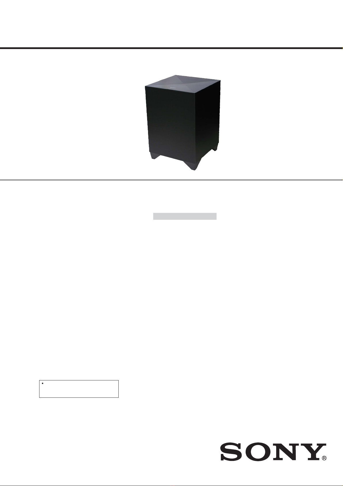
SA-WCT260H
ACTIVE SUBWOOFER
9-893-770-01
2013F33-1
© 2013.06
US Model
Canadian Model
AEP Model
UK Model
Australian Model
Ver. 1.0 2013.06
• SA-WCT260H is the active subwoofer in HT-
CT260H.
• All of the units included in the HT-CT260H
(SA-WCT260H/SA-CT260H) are required to
confirming operation of SA-WCT260H. Check
in advance that you have all of the units.
SPECIFICATIONS
POWER OUTPUT (reference)
130 W (per channel at 4 ohms,
100 Hz )
Speaker system
Subwoofer, Bass reflex
Speaker unit
130 mm (5 1/8 in) cone type
Rated impedance
4 ohms
Power requirements
120 V AC, 60 Hz (US and Canadian
models)
220 V - 240 V AC, 50/60 Hz (AEP, UK and
Australian models)
Power consumption
On: 30 W
Standby mode: 0.5 W or less
Dimensions (approx.)
271 mm × 390 mm × 271 mm
(10 3/4 in × 15 3/8 in × 10 3/4 in)
(w/h/d)
Mass (approx.)
6.3 kg (13 Ib 14 1/4 oz)
Wireless transmitter/receiver
Frequency ban d
2.4 GHz band (2.404 GHz -
2.476 GHz)
Modulation method
GFSK
Design and specifications are subject to
change without notice.
Standby power consumption: 0.5 W
or less (Sound Bar), 0.5 W or less
(Subwoofer)
Copyrights
This system incorporates Dolby* Digital
and the DTS** Digital Surround System.
* Manufactured under license from
Dolby Laboratories.
Dolby, and the double-D symbol are
trademarks of Dolby Laboratories.
** Manufactured under license under
U.S. Patent Nos: 5,956,674; 5,974,380;
6,487,535 & other U.S. and worldwide
patents issued & pending. DTS, the
Symbol, & DTS and the Symbol
together are registered trademarks &
DTS Digital Surround and the DTS
logos are trademarks of DTS, Inc.
Product includes software. © DTS, Inc.
All Rights Reserved.
The BLUETOOTH®word mark and logos
are registered trademarks owned by
Bluetooth SIG, Inc. and any use of such
marks by Sony Corporation is under
license.
This system incorporates High-Definition
Multimedia Interface (HDMI™)
technology.
The terms HDMI and HDMI High-
Definition Multimedia Interface, and the
HDMI Logo are trademarks or registered
trademarks of HDMI Licensing LLC in the
United States and other countries.
“x.v.Color”and “x.v.Color” logo are
trademarks of Sony Corporation.
“WALKMAN” and “WALKMAN” logo are
registered trademarks of Sony
Corporation.
“PlayStation®” is a registered trademark
of Sony Computer Entertainment Inc.
Other trademarks and trade names are
those of their respective owners.

SA-WCT260H
2
SAFETY CHECK-OUT
After correcting the original service problem, perform the follow-
ing safety check before releasing the set to the customer:
Check the antenna terminals, metal trim, “metallized” knobs,
screws, and all other exposed metal parts for AC leakage.
Check leakage as described below.
LEAKAGE TEST
The AC leakage from any exposed metal part to earth ground and
from all exposed metal parts to any exposed metal part having a
return to chassis, must not exceed 0.5 mA (500 microamperes.).
Leakage current can be measured by any one of three methods.
1. A commercial leakage tester, such as the Simpson 229 or RCA
WT-540A. Follow the manufacturers’ instructions to use these
instruments.
2. A battery-operated AC milliammeter. The Data Precision 245
digital multimeter is suitable for this job.
3. Measuring the voltage drop across a resistor by means of a
VOM or battery-operated AC voltmeter. The “limit” indication
is 0.75 V, so analog meters must have an accurate low-voltage
scale. The Simpson 250 and Sanwa SH-63Trd are examples
of a passive VOM that is suitable. Nearly all battery operated
digital multimeters that have a 2 V AC range are suitable. (See
Fig. A)
1.5 kΩ0.15 μF
AC
voltmeter
(0.75 V)
To Exposed Metal
Parts on Set
Earth Ground
Fig. A. Using an AC voltmeter to check AC leakage.
SAFETY-RELATED COMPONENT WARNING!
COMPONENTS IDENTIFIED BY MARK 0OR DOTTED LINE
WITH MARK 0ON THE SCHEMATIC DIAGRAMS AND IN
THE PARTS LIST ARE CRITICAL TO SAFE OPERATION.
REPLACE THESE COMPONENTS WITH SONY PARTS
WHOSE PART NUMBERS APPEAR AS SHOWN IN THIS
MANUAL OR IN SUPPLEMENTS PUBLISHED BY SONY.
ATTENTION AU COMPOSANT AYANT RAPPORT
À LA SÉCURITÉ!
LES COMPOSANTS IDENTIFIÉS PAR UNE MARQUE 0SUR
LES DIAGRAMMES SCHÉMATIQUES ET LA LISTE DES
PIÈCES SONT CRITIQUES POUR LA SÉCURITÉ DE FONC-
TIONNEMENT. NE REMPLACER CES COMPOSANTS QUE
PAR DES PIÈCES SONY DONT LES NUMÉROS SONT DON-
NÉS DANS CE MANUEL OU DANS LES SUPPLÉMENTS
PUBLIÉS PAR SONY.

SA-WCT260H
3
SECTION 1
SERVICING NOTES
ADVANCE PREPARATION WHEN CONFIRMING OP-
ERATION
All of the units included in the HT-CT260H (SA-WCT260H/SA-
CT260H) are required to confirming operation of SA-WCT260H.
Check in advance that you have all of the units.
You can link the Sound Bar (SA-CT260H)
and the subwoofer (SA-WCT260H) again
to enable wireless transmission between
them.
1Press LINK on the rear of the
subwoofer with the point of a
pen, etc.
The subwoofer keeps beeping for
a certain time. Perform steps 2 to 5
before the subwoofer stops
beeping.
2Press AMP MENU.
3Select “WS” with (select),
then press .
4Select “LINK,” then press .
AMP
MENU
5“START” appears, then press .
“SEARCH” appears, and the Sound
Bar searches for equipment that
can be used with Link. Proceed to
the next step within 1 minute.
To quit the Link function during a
search for equipment, press .
When subwoofer is linked with the
Sound Bar, the indicator on
the subwoofer lights up in green
and the subwoofer beeps once.
“OK” appears on the front panel
display.
If “FAILED” appears or the
subwoofer does not stop beeping,
perform the process again from
step 1.
6Press AMP MENU.
The AMP menu turns off.
NOTE OF REPLACING THE WS R BOARD
When the WS R board is exchanged, you must perform linking
between SA-CT260H and SA-WCT260H.
Linking method:
This operation requires a remote commander.

SA-WCT260H
4
MODEL IDENTIFICATION
Distinguish by model number label stuck on the rear side of a main unit.
MODEL NUMBER LABEL
– Rear view –
US and Canadian models
AEP model
UK model
Australian model
4-463-510-0s
4-463-513-0s
4-463-511-0s
4-463-512-0s

SA-WCT260H
5
SECTION 2
DISASSEMBLY
• This set can be disassembled in the order shown below.
2-1. DISASSEMBLY FLOW
SET
2-6. POWER BOARD
(Page 7)
2-7. AMP BOARD
(Page 8)
2-8. POWER-SUPPLY CORD (AC1)
(Page 9)
2-2. BACK COVER ASSY
(Page 5)
2-5. AMP BLOCK
(Page 7)
2-9. BOTTOM COVER BLOCK
(Page 10)
2-3. LED BOARD,
TOP COVER ASSY
(Page 6)
2-4. TOP PLATE
(Page 6)
Note: Follow the disassembly procedure in the numerical order given.
2-2. BACK COVER ASSY
1two screws
(BV3)
1two screws
(BV3)
3Pull out the power-supply cord.
2Remove the back cover assy in
the direction of an arrow.
4back cover assy
back cover assy
1two screws
(BV3)
A
A
A
1two screws
(BV3)
2Remove the back cover assy in
the direction of an arrow.
– Rear view –
(US, Canadian, AEP)
(UK, Australian)

SA-WCT260H
6
2-4. TOP PLATE
1six screws
(BV3)
1four screws
(BV3)
boss
boss
hole
hole
2Remove the top plate
in the direction of an arrow.
3top plate
Note: When installing the top plate,
make the position of two holes
match two bosses.
– Rear view –
1two screws
(BV3)
2-3. LED BOARD, TOP COVER ASSY
5screw
(BVTP2.6)
5screw
(BVTP2.6)
4connector
(XP11)
2Remove the top cover assy
in the direction of an arrow.
8top cover assy 3two claws
3two claws
6Remove the LED board
in the direction of an arrow.
7LED board
– Rear view –
1screw
(BV3)
1screw
(BV3)

SA-WCT260H
7
2two tapping screws
(P3.5 u12) 2tapping screw
(P3.5 u12)
2tapping screw
(P3.5 u12)
1speaker connector
(XP6)
4AMP block
3Remove the AMP block
in the direction of an arrow.
– Rear view –
1power-supply cord connector
(CN501)
5POWER board
4Remove the POWER
board in the direction
of an arrow.
– Rear view –
– Top view –
power-supply cord
POWER board
:ire VeWWiQJ
2connector
(XP12)
Insert is shallow
Insert is straight
to the interior.
connector
Insert is incline
connector
connector connector
connector connector
NG
OK
NG
Note: When you install the connector, please
install them correctly.
There is a possibility that this machine
damages when not correctly installing it.
3two screws
(BV3)
3two screws
(BV3)
2-5. AMP BLOCK
2-6. POWER BOARD

SA-WCT260H
8
2-7. AMP BOARD
8AMP board
5Remove the AMP board block
in the direction of an arrow.
3connector
(XP3) 1speaker connector
(XP6)
2connector
(XP12)
7heat sink
Insert is shallow
Insert is straight
to the interior.
connector
Insert is incline
connector
connector connector
connector connector
NG
OK
NG
Note: When you install the connector, please
install them correctly.
There is a possibility that this machine
damages when not correctly installing it.
4two screws
(BV3)
4two screws
(BV3)
6two screws
(BVTT3 u6)

SA-WCT260H
9
2-8. POWER-SUPPLY CORD (AC1)
3cord bush
cord bush
– Rear view –
POWER board
3RwerVXSSO\ FRrGVeWWiQJ
power-supply cord (AC1)
cord bush
claw
to POWER board
5power-supply cord
(AC1)
1power-supply cord
connector
(CN501)
power-supply cord
Note: When installing the power-supply cord (AC1),
check the direction of claw of cord bush and
install correctly.
– 7RS view –
2two claws
4back cover assy
8. $XVWraOiaQ

SA-WCT260H
10
2-9. BOTTOM COVER BLOCK
• JIG
When disassembling the set, use the following jig (for speaker
removal).
Part No. Description
J-2501-238-A JIG FOR SPEAKER REMOVAL
Note 1: Please spread a sheet
under a unit not to
injure top panel.
– Rear bottom view –
1Insert a flat-head screwdriver in
two slits behind a unit and raise
the bottom cover block a little.
total six bosses
3 All bosses are removed while
moving jig in the direction of
the arrow, and bottom cover
block is removed.
3 All bosses are removed while
moving jig in the direction of
the arrow, and bottom cover
block is removed.
2 Insert the jig into a space and raise
bottom cover block.
Note 2: When using a jig, please work
so as not to injure bottom cover
block.
2 Insert the jig into a space and raise
bottom cover block.
Note 2: When using a jig, please work
so as not to injure bottom cover
block.
4Remove the bottom cover block
in the direction of an arrow.
5bottom cover block

SA-WCT260H
11
SECTION 3
DIAGRAMS
3-1. BLOCK DIAGRAM
MCU
STM8S003F3
Audio
Processor
STA309
PBTL
I2S
I2C I2C
Mute
PWM 4¡130W
THD 30%
POWER SUPPLY
Wireless
IA2S
DC-DC
Power Stage
STA518

12
SA-WCT260H
SECTION 4
EXPLODED VIEWS
01 A-1952-852-A TOP COVER ASSY
2 3-087-053-01 +BVTP2.6 (3CR)
3 4-472-284-01 SCREW (+P 3.5X12)
04 A-1952-851-A BACK COVER ASSY
5 9-885-188-46 LED BOARD, COMPLETE
6 3-077-331-41 +BV3 (3-CR)
Ref. No. Part No. Description Remark Ref. No. Part No. Description Remark
Note:
• -XX and -X mean standardized parts, so
they may have some difference from the
original one.
• Items marked “*” are not stocked since
they are seldom required for routine ser-
vice. Some delay should be anticipated
when ordering these items.
• The mechanical parts with no reference
number in the exploded views are not sup-
plied.
• Color Indication of Appearance Parts Ex-
ample:
KNOB, BALANCE (WHITE) . . . (RED)
Parts Color Cabinet’s Color
• Abbreviation
AUS : Australian model
CND : Canadian model
The components identified by mark 0
or dotted line with mark 0are critical for
safety.
Replace only with part number specified.
Les composants identifiés par une marque
0sont critiques pour la sécurité.
Ne les remplacer que par une pièce por-
tant le numéro spécifié.
4-1. COVER SECTION
AMP section
wooden box section
A
1
3
36
6
3
3
4
A
2
5
2
6
6
6
6

13
SA-WCT260H
4-2. AMP SECTION
51 4-465-770-01 BRACKET
52 9-885-188-47 WS R BOARD, COMPLETE
53 4-465-769-01 BUTTON (?/1)
054 9-885-188-43 POWER BOARD, COMPLETE (US, CND)
054 9-885-188-44 POWER BOARD, COMPLETE (AEP, UK, AUS)
55 9-885-188-45 AMP BOARD, COMPLETE
56 4-472-176-01 CORD BUSH
57 3-077-331-41 +BV3 (3-CR)
0AC1 9-885-188-34 CORD, POWER-SUPPLY (US, CND)
0AC1 9-885-188-35 CORD, POWER-SUPPLY (AEP)
0AC1 9-885-188-36 CORD, POWER-SUPPLY (UK)
0AC1 9-885-188-37 CORD, POWER-SUPPLY (AUS)
#2 7-685-871-01 SCREW +BVTT 3X6 (S)
#3 7-685-546-19 SCREW +BTP 3X8 TYPE2 N-S
Ref. No. Part No. Description Remark Ref. No. Part No. Description Remark
#2
#2
#3
AC1
not supplied
not supplied
not supplied
not supplied
53 54
56
55
52
51
57
57
57
57
57
57
57
57
57
57
57
57
57
57
57 57
57
57
57
57
57
57 57
57

14
SA-WCT260H
4-3. WOODEN BOX SECTION
101 4-474-769-01 CUSHION (SW FOOT)
0102 4-465-773-01 BOTTOM COVER
SP3 A-1952-848-A WOODEN BOX ASSY (UC2)
(Including LOUDSPEAKER) (US, CND)
SP3 A-1952-849-A WOODEN BOX ASSY (CEL)
(Including LOUDSPEAKER) (AEP, UK, AUS)
Ref. No. Part No. Description Remark Ref. No. Part No. Description Remark
101
102
101
101
101
SP3

MEMO
SA-WCT260H
15

SA-WCT260H
REVISION HISTORY
Ver. Date Description of Revision
1.0 2013.06 New
Table of contents
Other Sony Subwoofer manuals

Sony
Sony XS-GTR1212L User manual

Sony
Sony XS-GTR100L Installation instructions manual

Sony
Sony SA-NA9ES User manual

Sony
Sony SAW-M20 User manual

Sony
Sony SA-WM500 User manual

Sony
Sony XS-LD106P5 - 10" Subwoofer User guide

Sony
Sony XS-L103P5B Product guide

Sony
Sony XS-L101 Product guide

Sony
Sony XS-L1030 User manual

Sony
Sony SA-WM40 User manual

Sony
Sony XS-L1090P5 Marketing Product guide

Sony
Sony XS-L1290P5 User manual

Sony
Sony XS-LB10S User manual

Sony
Sony XS-L836 User manual

Sony
Sony L1035D4 Product guide

Sony
Sony SA-WM200 User manual

Sony
Sony SWF-BR100 User manual

Sony
Sony XS-NW1200 User manual

Sony
Sony SA-W551 User manual

Sony
Sony XS-L102P5S Product guide