Tecnoclima WIMBLEDON 145 Manual

- 1 -
TECHNICAL INFORMATION
ASSEMBLY, USE AND MAINTENANCE
AUTONOMOUS MONO-BLOCK
AIR TREATMENT UNIT
WIMBLEDON
MODEL
GB
- 2 -
Dear Customer,
Thank you for choosing an AUTONOMOUS MONO-BLOCK AIR TREATMENT UNIT,
WIMBLEDON series, an innovative, modern, high-quality and high-performance product, which
will ensure your wellbeing and which will be noiseless and safe in the long term; especially, if
you are supported by TECNOCLIMA Technical Assistance Service, which is specifically skilled
and trained to maintain the highest efficiency level of the machine at the lowest operating costs
and which can provide you with original spare parts, if needed.
This User Manual includes important instructions and recommendations that should be
complied with, in order to easily install and to better use the AUTONOMOUS MONO-BLOCK
AIR TREATMENT UNIT, WIMBLEDON series.
Thank you, once again.
TECNOCLIMA S.p.A.
COMPLIANCE
The air treatment unit, WIMBLEDON series, comply with:
•Machinery directive 2006/42/EC
•Low Voltage Directive 2006/95/EC
•Regulation UE 2016/426 for Gas equipment
•Electromagnetic Compatibility Directive 2004/108/EC
PIN NUMBER
The PIN number is specified on the technical data plate.
RANGE
Throughout this manual, reference is made to the TYPE. The table hereunder indicates the range or
products and relation between TYPES and TRADE NAMES.
TYPE
TRADE NAME
1
WIMBLEDON 145
2
WIMBLEDON 245
WARRANTY
The warm air heater is covered by a SPECIFIC WARRANTY, as from the date of purchase of the
appliance, to be documented by the Purchaser; if she/he cannot do this, the warranty shall apply as from
the data of manufacture of the appliance. The warranty terms are specified in detail in the WARRANTY
CERTIFICATE, delivered together with the appliance, which should be read with great care.

GENERAL INFORMATION
- 3 -
CONTENTS
GENERAL INFORMATION:
Compliance 2
Pin number 2
Range 2
Warranty 2
Contents 3
General instructions 4
Basic Safety rules 5
Disposal information 5
Appliance description 6
Identification 8
Structure 9
Heat exchanger scheme 10
Dimension and weight 11
Technical data 12
Information requirements 2016/2281 13
INSTALLATION AND SETTING INSTRUCTIONS:
Product receipt 14
Movement and transport 14
Transport locks 15
Position 15
Clearance area 16
Fuel connection 16
Smoke exhaust 16
Condensate drain connection 18
Condensate drain siphon (supplied with the machine) 19
Level switch (supplied with the machine) 20
Air outlet-intake connection 21
Combustion air 22
Gas supply line 22
Fixed protections 22
Gas burner and relevant supply ramp 22
Air outlet temperature probe 23
Safety thermostats 24
Wiring diagram 26
Electric connection 32
Start-up and stop of the treated air fan 33
Fan speed setting 33
Controls 34
Electric panel controls 35
Failures and troubleshooting 35
TECHNICAL ASSISTANCE INSTRUCTIONS:
Maintenance 36
Gas burner cleaning 36
Condensate drain system cleaning 36
Fan unit maintenance 36
LIMIT thermostat maintenance 37
Maintenance of safety devices 37
Exchanger cleaning 37
Assistance 38
Modulating thermal power regulator (RWF 40) 38
Notes 39
In the manual, the following symbols are used:
WARNING = operations requiring appropriate care and preparation
FORBIDDEN = operations that MUST NOT be performed, in any case
This manual comprises 40 pages.

GENERAL INFORMATION
- 4 -
GENERAL INSTRUCTIONS
This instruction manual is an integral part of the equipment and delivery, and must be preserved with care. In case o f equipment resale, the
manual must be delivered to the new owner or user. In case of loss of or damages to this manual, you are kindly requested to contact the
Manufacturer or the Technical Assistance Service of your area.
After removing the packaging, check that its content is in good condition and complete. If it is non-conforming, please contact the Organisation
that sold the appliance.
Air treatment units must be installed by a qualified company, which at the end of the work must provide the owner wi th a declaration of
conformity stating that the installation complies with the best practice and the applicable national and local regulations, a s well as the indications
of this instruction manual.
This equipment has been designed for room heating and must never be used for other purposes that are not compatible with its functioning
characteristics.
Any contractual or extra-contract liability of the Manufacturer in respect of damages caused to people, animal or things by mistakes in
installation, setting or maintenance or by the improper use of the machine is excluded.
A too high temperature is unhealthy and it is a pointless waste of energyDo not leave the rooms closed for a long time. Regularly
open windows to facilitate a proper air renewal.
Smells and fumes may be produced during the first start-up, due to the evaporation of the liquid that protects the heat exchanger during
storage; this event is normal and disappears after a short period of operation. Air the room properly.
If you plan not to use the machine for a long time, carry out at least the following operations:
•
turn the appliance’s master switch and the plant’s master switch to “OFF”
•
close the central cock that feeds the fuel
If the air treatment unit is shut down for long periods of time, it is recommended to inform the Technical Assistance Service or a professional
staff qualified to restart it.
The appliance must be equipped exclusively with original accessories. The Manufacturer shall not be held liable for any damag e caused by
improper use of the equipment or by the use of non-original materials or accessories.
References to Laws, Regulations, Directives and Technical Rules mentioned in this manual are made only for information
purposes and as they are in force when the manual is printed.
If new regulations or amendments to current laws go into effect, this
shall not oblige the Manufacturer with regards to third parties.
Servicing or maintenance operations shall be carried out by the After-sales Service or by qualified personnel, as provided for by this handbook.
Never modify nor tamper with this equipment, since this might cause hazardous situations, and the Manufacturer shall not be h eld liable for any
consequent damage.
The systems that shall be prepared (gas piping, power supply etc.) shall be properly secured and shall never become obstacles, involving the risk
of stumbling.
The Manufacturer is responsible for the product compliance with Laws, Directives or Construction Standards in force when the product
is marketed. Knowledge and compliance with the laws and regulations concerning plant design, installation, operation and
maintenance of the plant are the exclusive responsibility of the Designer, Installer and User, respectively
The Producer shall not be held responsible for failure to comply with the instructions of this manual, for the consequences of any
operations carried out and not specifically provided for or for translations open to misinterpretation
.
The equipment functions with airflow and variable thermal power and works with combustion fuels condensate.
BASIC SAFETY INSTRUCTIONS
GENERAL INFORMATION
- 5 -
Bear in mind that if you use products powered trough electric power, gas, etc., you should comply with some basic rules,
such as:
Children and non-assisted disabled persons should not use the air treatment unit.
It is forbidden to activate electric devices or appliances, such as circuit breakers, domestic appliances etc. if you notice a smell of fuel or unburnt
products. In this case:
•
Open the doors and windows to ventilate the room;
•
Close the fuel supply device;
•
Call the Technical Assistance Service for quick intervention, or contact professionally qualified personnel.
It is forbidden to touch the appliance barefoot and with wet limbs.
It is forbidden to perform any cleaning and maintenance operations before disconnecting the appliance from the power supply by turning the
system’s master switch to “OFF”, and before shutting off the fuel.
It is forbidden to modify safety or control systems without the authorisation and the instru ctions of the Manufacturer of the appliance.
It is forbidden to pull, detach, twist the power cables from the appliance, even if it is disconnected from the power supply.
It is forbidden to open the doors providing access to the interior of the appliance before turning the system’s master switch to “OFF”.
It is forbidden to dump, abandon or leave the packaging materials (cardboard, staples, plastic bags etc.) within the children ’s reach, as they
could be a potential source of hazard.
It is forbidden to install the appliance near flammable material or in rooms characterised by the presence of aggressive atmospheres.
It is forbidden to put any objects on the equipment or insert them into the cover grid or into the fuel products discharge pi pes.
It is forbidden to touch the exhaust duct for combustion products, as during normal operation it may reach high temperatures, hazardou s by
contact.
It is forbidden to use adapters, multiple jacks and extensions for connecting the appliance.
It is forbidden to install the equipment beyond its operational and functioning limits indicated in this manual.
The warm air heater shall not be directly installed in small areas lacking proper ventilation, since the air intake might
cause a remarkable depression within the room, causing serious problems
.
DISPOSAL INFORMATION
Disposal of the appliance must be done by an authorized company and in compliance with the
Local and Current Laws.
Before giving the waste to the Authorized Collection Centers, the various materials that compose
it must be dismantled and separated:
•ferrous materials;
•aluminum;
•electric wire;
•seals;
•insulating materials;
•plastic materials;
•electronic boards.

GENERAL INFORMATION
- 6 -
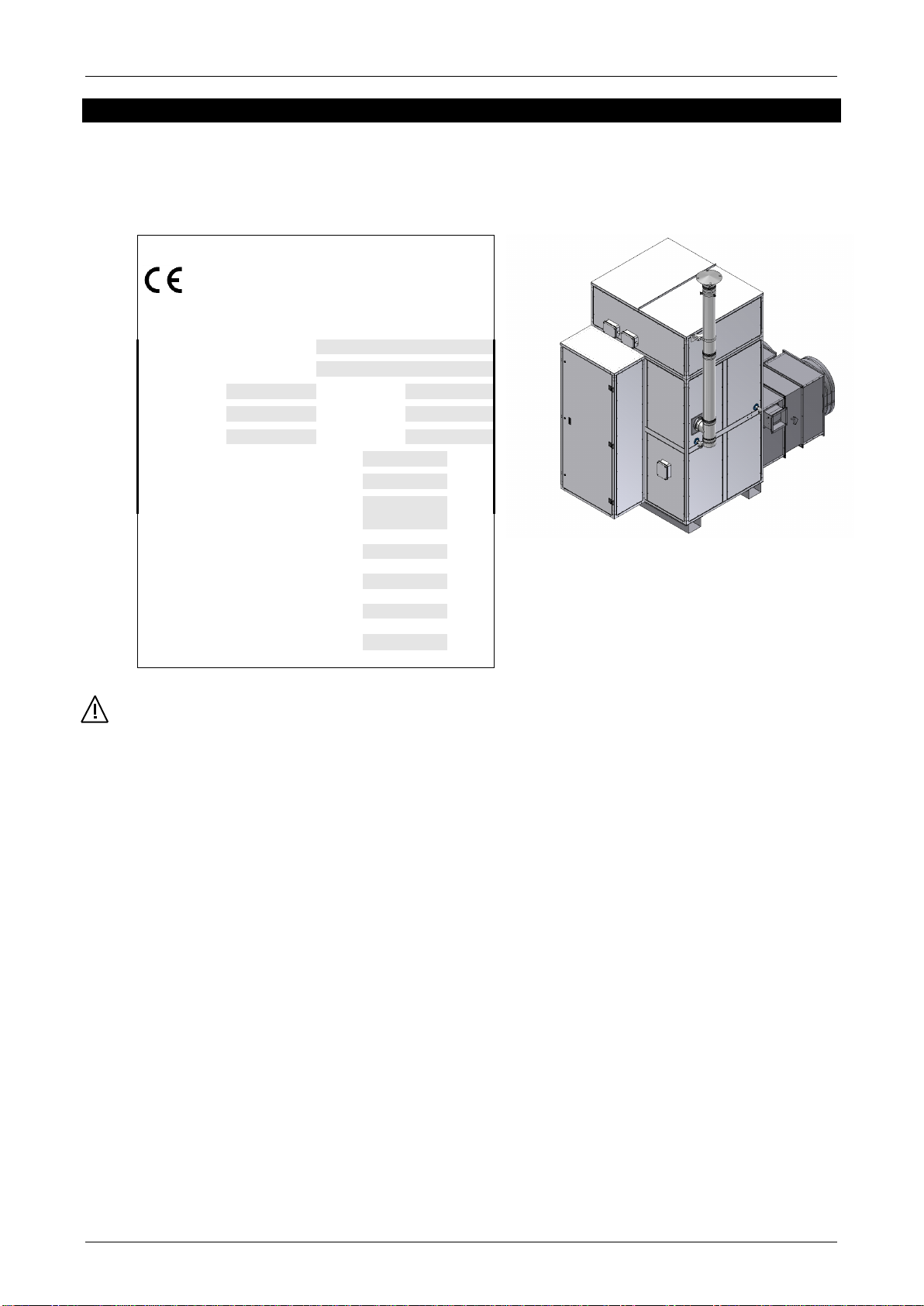
DESCRIPTION
The air treatment unit essentially represents a thermal group that exchanges the combustion products of a
forced-air gas burner with an air flow generated by a group of highly efficient fans.
The air to be heated is sucked by the latter and when it touches the hot surfaces of the heat exchanger, the
air temperature rises; the air can be distributed both directly and through special ducts.
The characteristics of the centrifugal fan make the equipment suitable to be installed on plants needing the
distribution of hot air through ducts or, in general, when it is necessary to have static pressure.
This heating system makes it possible to remarkably reduce the plant costs and ensure savings in operating,
being particularly suitable for discontinuous and occasional use.
The special configuration of the counter-current flow heat exchanger optimises the heat exchange and
makes the equipment to work with condensate.
Besides, the equipment is realised in a way that it can operate with variable heating power and air flow, in
order to adapt to the real heating requirements of the environment.
In summer it is possible to operate the ventilating unit only.
GENERAL DESIGN AND FUNCTIONAL CHARACTERISTICS:
Heat exchanger:
It is made of a welded steel sheet, easy accessible for cleaning and maintenance. It is made up of:
•Combustion chamber made of AISI 430 STAINLESS STEEL, with a low thermal load, with
ovoidal shape and suitable volume.
•Patented, modular exchange elements of AISI 304 STAINLESS STEEL, wide surface, with
whirlpooling marks and counter-current position, in order to optimize the thermal exchange. The
exchange elements are inclined to facilitate the drainage of combustion product condensate.
•Exhaust manifold of AISI 304 STAINLESS STEEL, with shutters for inspection.
Supporting frame:
The supporting frame is made of press-folded, powder-painted and galvanised steel.
The mitre joints are made of strong and die-cast aluminium and are fully designed by the Manufacturer.
Closing panels:
The closing panels are made of coated galvanised steel or of pre-coated sheets; they are thermally insulated
with a mineral fibre mat, and are provided with galvanised counter-panel sheets. These panels can be
removed to perform the ordinary internal inspection.
Ventilation unit
The unit is made up of a centrifugal fan with backward blades and low noise emission and high efficiency;
they are powered by an electric motor connected by means of a belts and pulleys driven transmission
system, which provides this product with high reliability of the plant it is to be used with.
“LM” safety thermostat:
The air treatment unit is equipped with a safety thermostat whose sensors is placed on the air outlet. It
stops the burner if the air is anomalously overheated. It has to be manually reset, after removing the cause
that has caused its intervention.
GENERAL INFORMATION
- 7 -
“TR” Safety thermostat :
The air treatment unit is equipped with a safety thermostat whose sensor is placed on the air outlet. It stops
the burner if the air is anomalously overheated It has to be manually reset, after restoring normal operating
conditions.
“FAN”function:
To adapt the machine to the air treatment unit of pressure-static structures, the fan group operates
continuously.
Smoke exhaust opening
The equipment is fitted with a circular opening, to which the combustion products exhaust ducts is safely
connected and fixed. The stove to be used must conform to standards and is to be certified
Condensate drain connector.
Due to the fact that the equipment operates with combustion products condensate, the appliance is fitted
with a threaded condensate drain union to be connected in compliance with the relevant Regulations in
force.
GENERAL INFORMATION
- 8 -
IDENTIFICATION
The warm air heaters can be identified through:
•The Technical Plate, applied to the equipment, and indicating its technical/performance data.
If the plate is lost or damaged, request a duplicate to the Technical Assistance Service,
MANUFACTURER’S IDENTIFICATION DATA
AIR TREATMENT UNIT
Model
Production number
Country
PIN
Category
Codes
Type
Year
Max thermal capacity
kW
Max thermal power
kW
Max air capacity
m³/h
Useful static pressure
Pa
Three-phase power supply
Fan engine power
kW
Fan engine max power
A
Electric protection degree
IP
GENERAL INFORMATION
- 9 -
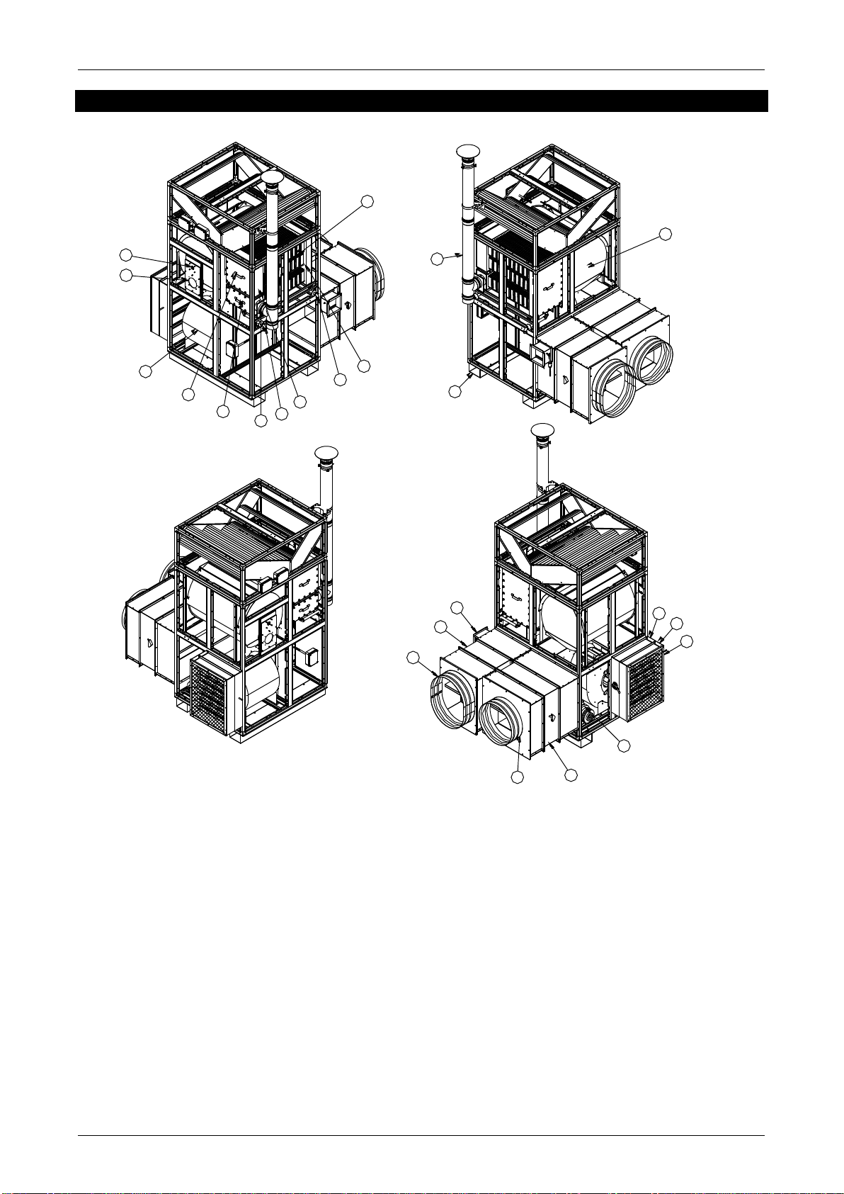
STRUCTURE
1
2
3
4
5
5
6
7
8
9
10
11
11
17
18
20
18
19
15
16
13
12
14
1) Smoke pipe
2) Combustion chamber
3) Front fume manifold
4) Rear fume manifold
5) Heat exchanger inspection shutters
6) Fume exhaust fitting
7) Burner head
8) Flame inspection window
9) Centrifugal fan
10) Fan electric engine
11) Condensate drain fitting
12) Smoke discharge Kit
13) Lower struts
14) Outside air controlling shutter
15) Gravity shutter on outside air
16) Protection net
17) Overpressure shutter
18) Fire protection shutter
19) Recirculation air suction fitting
20) Hot air outlet fitting
Note:
In order to make the internal parts visible, the drawing represents the equipment without the housing of the
burner and electrical panel.
INSTALLATION AND SETTING INSTRUCTIONS
- 10 -
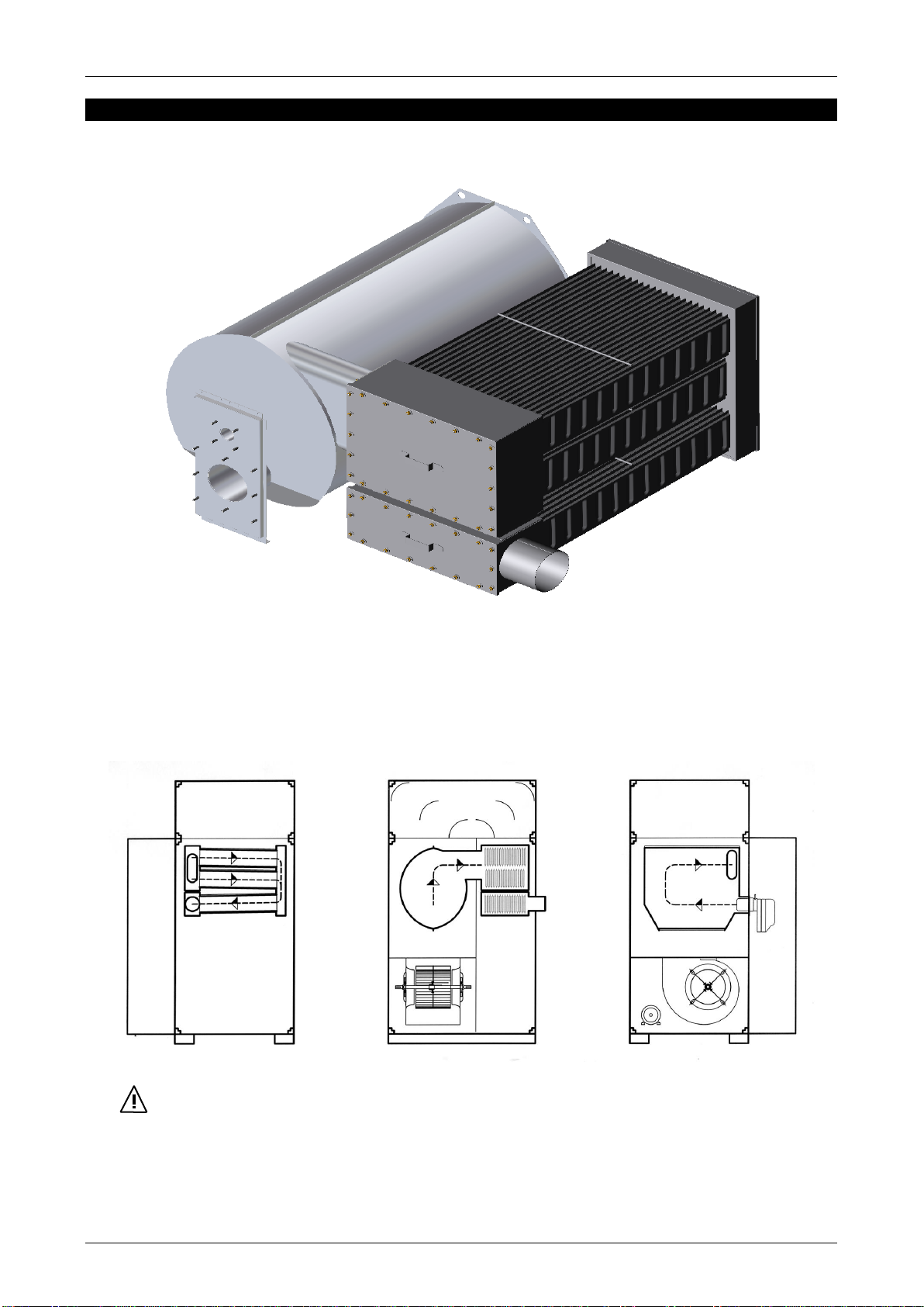
HEAT EXCHANGER SCHEME
Axonometric image of the heat exchanger:
Combustion products
•create an inversion in the combustion chamber;
•are transferred into the first smoke collector and then flow into the first row of exchanging
elements;
•arrive to the second smoke collector and then flow into the second row of exchanging elements;
•are discharged from the equipment through the circular junction.
In order to keep the combustion products speed at an optimal level, the section of the smoke
passage has a decreasing gradient.
The smoke duct elements are slightly inclined to facilitate the condensate drain.
The two fluids (air \ combustion products) are in counter-current.
These are some of the design specifications that make this innovative heat exchanger
extremely efficient.
- 11 -
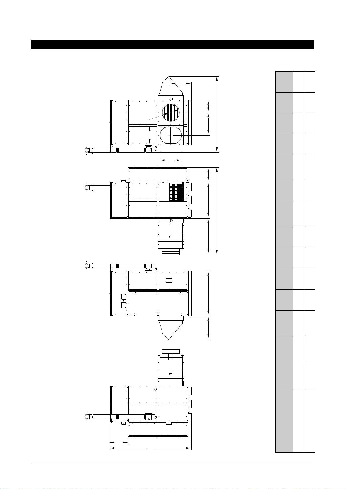
DIMENSIONS AND WEIGHT
I
F
K
M
D
B
1250 C
A
812
G
H
J
E
L
WEIGH
T
(kg)
1200
1500
M
(mm)
600
800
L
(mm)
600
600
K
(mm)
750
914
J
(mm)
2616
2935
I
(mm)
709
559
H
(mm)
2815
2620
G
(mm)
632
651
F
(mm)
435
430
E
(mm)
780
930
D
(mm)
500
700
C
(mm)
3000
3450
B
(mm)
1250
1500
A
(mm)
1550
1800
TYPE
1
2
- 12 -
TECHNICAL DATA
TYPE
1
2
MAX NOMINAL THERMAL POWER
kW
152,3
247,5
(burned)
Kcal/h
130.980
212.850
MAX NOMINAL THERMAL POWER
kW
148,2
240,0
(useful)
kcal/h
127.450
206.400
PERFORMANCE AT MAX. THERMAL POWER 1)
%
97,3
96,9
MAX. PRESSURE IN COMBUSTION CHAMBER
mbar
0,6
0,7
GROSS SMOKE TEMPERATURE (2)
°C
80
90
CONSUMPTION AT NOMINAL THERMAL POWER (3)
- G20 methane gas
Nm3/h
16,1
26,2
- G25 methane gas
Nm3/h
18,7
30,5
- G31 propane gas
Nm3/h
6,2
10,1
- G30 butane gas
Nm3/h
4,7
7,7
NOMINAL AIR CAPACITY
m3/h
14.000
23.000
USEFUL NOMINAL STATIC PRESSURE
Pa
150
200
NOMINAL AIR THERMAL GRADIENT (t)
°K
31
31
PRE-CALIBRATION OF THE SAFETY THERMOSTAT (MAN.
RESET)
°C
90
90
PRE-CALIBRATION OF THE SAFETY THERMOSTAT (AUTO.
RESET)
°C
70
70
TREATED AIR FAN
- brand
NICOTRA
NICOTRA
- quantity
N°
1
2
- model
RDH 450 L
ADH 315 L
TREATED AIR FAN ENGINE
- polarity
N°
4
4
- quantity
N°
1
2
- unit electric power
kW
4,0
5,5
- max. design absorbed unit power
A
8,4
11,5
TRASMISSION
Driving pulley (engine)
- model
mod.
PRC 187 2B
PRC 178 2B
- pitch
mm
148180
139171
Driven pulley (fan)
- model
mod.
D 150 2B
D 160 2B
- pitch
mm
150
160
Driving belts
mod.
B 68
SPB 1450 LW
GENERAL ELECTRIC POWER SUPPLY
Three-phase
400V 50Hz 3N
400V 50Hz 3N
RECCOMENDED USE CONDITIONS
- outside air temperature range
°C
-15/+35
-15/+35
- nominal suctioned air temperature
°C
+15
+15
- suctioned air temperature range
°C
-15/+35
-15/+35
NOx CLASS
4
4
DESTINATION COUNTRY
ITALIA
ITALIA
TYPE
B23
B23
CATEGORY
See burner
See burner
1) Referred to a lower heating power (Hi)
2) Referred to a comburent air temperature of +15°C
3) G20 methane gas: Hi = 34,02 MJ/Nm3
G25 methane gas: Hi = 29,25 MJ/Nm3 (not available in Italy)
G31 propane gas: Hi = 88,00 MJ/Nm3
G30 butane gas: Hi = 116,09 MJ/Nm3

- 13 -
INFORMATION REQUIREMENTS 2016/2281
TYPE
1
2
Type of installation:
B23
B23
Type of fuel:
Gassoso
Gassoso
Capacity:
P rated,h
kW
148
240
P min
kW
74
123
Useful efficiency(1):
nom
%
93
92,5
pl
%
95,4
95,4
Electric power consumption:
el max
kW
0,18
0,18
el min
kW
0,18
0,18
el sb
kW
0,01
0,01
Other items:
F env
%
1
1
P ign
kW
-
-
s,flow
%
94
94
s,h
%
86,7
86,6
1) Refferd to the high heating value (Hs):
•Gas : gas G20 (37,78 MJ/Nm³);
Definitions:
P rated,h
Rated heating capacity
P min
Minimum heating capacity
nom
Useful efficiency at rated heating capacity
pl
Useful efficiency at minumum capacity
el max
At rated heating capacity
el min
At minimal capacity
el sb
In standby mode
F env
Envelope loss factor
P ign
Ignition burner power consumption
s,flow
Emission efficiency
s,h
Seasonal space heating energy efficiency
Note:
The data in the table is referred to the high heating value of the fuel (Hs), nominal air flow rate and a 15
mm of mineral wool

- 14 -
PRODUCT RECEIPT
The air treatment unit is supplied together with:
•Document envelope including:
oUser guide
oWarranty certificate
oSpare parts catalogue
oBarcode tags
oCondensate discharge syphon
oLevel switch
MOVEMENT AND TRANSPORT
The machine is used through a forklift:
GENERAL INSTRUCTION TO MOVE AND TRANSPORT THE APPLIANCE
WARNING!
The appliance should be moved by adequately equipped persons and with tools suitable for the appliance
weight.
The machine should be extremely carefully transported and moved, so as to prevent damages to the
machine and dangers for those performing the operation.
While the machine is being transported or moved, do not stay near it.
The forks to be used should be at least as long as the machine width.
A lifting beam (not included in the shipment) must be employed, if belts and ropes are used in the handling,
in order to avoid damaging the equipment structure by the pressure of the latter.
If it is necessary to line up several machines, the stacking index (written on the packaging) should
compulsorily be complied with and the boxes should be lined up so as not create unstable stacks.
We suggest using protection gloves.

INSTALLATION AND SETTING INSTRUCTIONS
- 15 -
TRANSPORT LOCKS
To prevent damage to the appliance during transportation, some red mechanical locks can be used, limiting
the movement of some internal elements. Their identification and the instructions to remove them are
specified on a self-sticking tag placed on the appliance.
THE LOCKS MUST BE REMOVED BEFORE THE FIRST COMMISSIONING.
POSITION
The installation setting should be defined by the plant designer or by a competent person and it should take
into account the technical needs as well as the relevant laws and regulations in force; specific authorizations
are usually required. (e.g.: regulations concerning city planning, architecture, fire prevention, environmental
pollution, noise level, etc.)
Therefore, we suggest requesting and obtaining the relevant authorizations before installing the machine.
If the appliance is to be installed in sport facilities, specific skills and experience are required
since the following requirements should be met: highest quietness, limited air stratification, air
distribution uniformity, without generating unpleasant currents. If you have any doubt, pleas
ask the Manufacturer to receive the appropriate technical support.
To be properly installed, the air treatment unit should:
•be laid on all the lower frame rang;
•be placed on a flat, non wet surface, capable of bearing its weight;
•be placed on a surface that is high and solid enough to avoid transmission of vibrations to the premises
underneath;
•be placed in compliance with the specified distances so that air can properly flow and that ordinary
cleaning and maintenance operations can be performed;
•be placed in compliance with the specified distance from inflammable substances;
•be easily connected to the gas grid;
•be placed close to a power socket;
•be close to the duct which discharges the combustion products out of the premises;
•be such that all the maintenance and control operations can be easily performed;
•be fitted with the ventilation openings required by the relevant regulations.
We suggest not installing the machine :
•in places with aggressive atmosphere;
•in narrow places where the heater noise level can be magnified by reverberation and resonance;
•in corners where leaves can deposit or any other materials might obstruct the air opening, thus
decreasing the heater efficiency;
•in places with an higher pressure;
•in places with a lower pressure;

INSTALLATION AND SETTING INSTRUCTIONS
- 16 -
CLEREANCE AREA
The machine shall be easily and safely reached without needing special equipment (ladders -
movable platforms -etc.). Around the machine, minimum distances shall be complied with so that the
control and/or maintenance operations can be performed and that no obstacles block the air flow.
WARNING!
Any Laws or specific regulations requirements (e.g. fire prevention) shall be complied with. Consult the plant
designer.
FUEL CONNECTION
The machine should be connected to the gas (GPL or butane) network by qualified personnel in compliance
with installation instruction.
For appliances fuelled by gas, we recommend installing a leakage detector controlling an electric valve that
stops the gas supply if any leakage is detected.
.
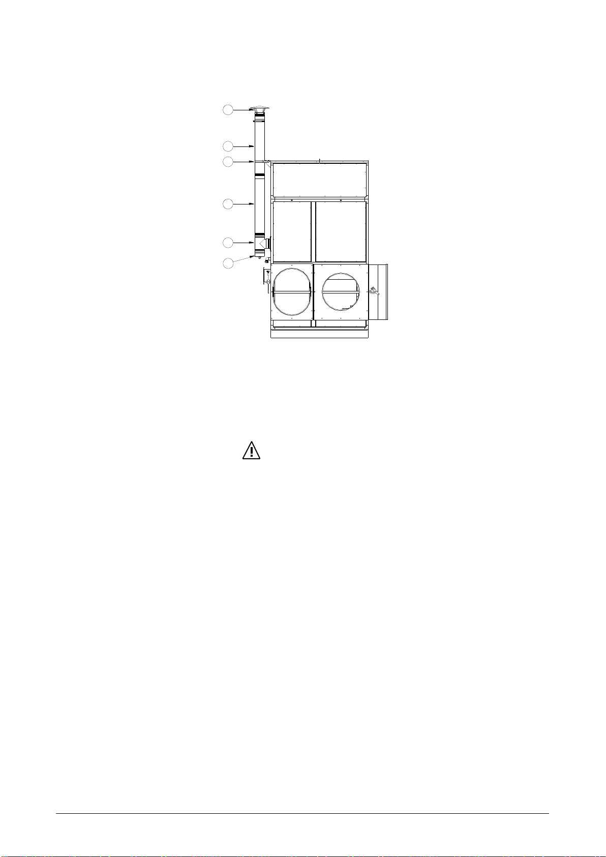
SMOKE EXHAUST PIPE
The height of the smoke exhaust fitting is as mentioned in the figure hereunder:
P
N
O
TYPE
N
(mm)
O
(mm)
P
(mm)
1
150
692
1474
2
180
879
1265
The smoke duct and chimney flue connection must be made in conformity with the Standards and
Legislations in force; they are to be made with rigid metal ducts, resistant to combustion mechanical,
thermal, and chemical stress
The smoke ducts connecting the equipment to the chimney flues must be easy to
dismantle; this is an indispensable condition to allow the checking and internal cleaning
of the heat exchanger.
- 17 -
Connection of the air treatment unit to the flue:
2
1
3
5
6
4
1. Condensate drain fitting.
2. T-shape joint
3. Flue.
4. Bracket.
5. Flue.
6. Terminal.
WARNING!
All stove components must be CEE certified.
There must be a condensate drain at the lowest part of the smoke duct (see diagram),
in order to avoid condensate backflow from the chimney flue to the air treatment unit.
The total weight of the smoke exhaust pipe must not weigh on the appliance.
It is mandatory to install a device (ex. level switch), which stops burner in case of
accidental clog of the condensate drain (see also the “condensate drain” paragraph).
Moreover, we recommend:
•avoid or however limit horizontal sections which in all cases should have a rising
gradient;
•use ducts having a smooth internal surface, made of material resistant to the flue gas
thermal and chemical stresses, with equal or higher diameter than the one of the
connection on the appliance;
•avoid tight curves and section reduction;
•have a cockpit for the combustion products sampling and analysis;
•adequately connect the smoke exhaust duct;
•have a suitable terminal to avoid rainwater infiltration into the equipment, and
simultaneously, to avoid high loss of load.

INSTALLATION AND SETTING INSTRUCTIONS
- 18 -
The chimney flue must guarantee minimum depression, as provided for by Technical Standards in force,
taking into consideration that the pressure is “zero” at the joining point with the smoke duct.
Non-insulated exhaust ducts are a source of potential hazard.
Inadequate or wrongly sized chimney flues or smoke ducts may amplify the combustion noise and negatively
influence the combustion parameters.
The joints must be sealed with materials resistant to thermal and chemical stress caused by combustion
products.
Crossings through walls and/or roofs, if any, must be performed up to standard, in order to avoid hazards of
fire and/or water infiltration.
CONDENSATE DRAIN CONNECTION
The condensate drain system should comply with the relevant European, National and Local Standards, and
the need for a neutralisation treatment should be checked.
We provide the following instructions, for information purposes:
•the condensate drain system should be dimensioned and made in a such a way that liquids can flow out,
without leaking;
•all condensate drain unions should be independently connected, and they should not be combined in one
duct;
•smokes must be prevented from being discharged through the condensate drain system; therefore a
syphon should compulsorily be installed.
•Condensate that may accumulate in the chimney flue, must never be permitted to backflow into the
equipment. A specific condensate drain must be created;
•The system should have a proper gradient. Pipes should not be installed at the same level of the machine
nor in counter-inclination.
•In case of connection to the domestic sewage net, a suitable trap or equivalent device is to be used in
order to prevent any backflow from the sewage net;
•The system must be made in a way as to prevent the freezing of the liquids it contains, in all
expected operating conditions;
•The system is to be provided with a device that stops the burner in case of accidental clog of the
condensate drain system, in order to avoid hazard situations or unhealthy combustion;

INSTALLATION AND SETTING INSTRUCTIONS
- 19 -
Position of condensate drain fittings –air treatment unit:
R
Q
S
1" GAS
TYPE
Q
(mm)
R
(mm)
S
(mm)
1
120
1.235
968
2
138
999
1.185
The air treatment unit is provided with two condensate drain fittings, which must be connected to the drain
system. The fittings must never be clogged.
CONDENSATE DRAIN SYPHON (SUPPLIED WITH THE APPLIANCE)
In order to prevent leakage of combustion products from the condensate drain and the backflow of sewage
fumes, the siphons should be installed (one for each condensate drain system)
Condensate drain syphon image and section:
INSTALLATION AND SETTING INSTRUCTIONS
- 20 -
Connection to the condensate drain fittings
WARNING
Pipes with external diameter ranging between 24 and 30 mm are to be used in connecting the air
treatment unit to the syphon. The head must not be smaller than 25 mm.
The total weight of the condensate drain system must not weigh on the equipment, and must be
suitably and separately mounted.
The configuration of the condensate drain system must facilitate the removal of the inspection panels.
The condensate drain system must be easily disassembled to perform inspection and/or maintenance
operations.
The two-condensate drain systems of the unit should be separately connected.
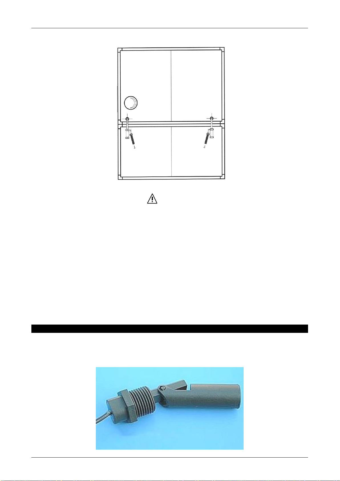
LEVEL SWITCH (PROVIDED WITH THE APPLIANCE )
A level switch must compulsorily be installed in the chimney flue “T”-shaped fitting, in order to stop the
burner in case of accidental flooding of the heat exchanger (ex. in case of failure in the condensate drain
system)
condensate
drain
condensate
drain
This manual suits for next models
1
Table of contents


