Kaysun KRE-500D1 Operating instructions

Thank you very much for purchasing our air conditioner.
Before using your air conditioner, please read this manual carefully and keep it for future
reference.
INSTALLATION & OWNER’S MANUAL
KRE (Heat Recovery Ventilation)
KRE-500D1
KRE-1000D1
KRE-1500D1
KRE-2000D1

WARNING
If the supply cord is damaged, it must be replaced by the manufacturer or its service agent or a simi-
larly qualied person in order to avoid a hazard.
An all-pole disconnection device which has at least 3mm separation distance in all pole and a
residual current device(RCD)with the rating of above 10mA shall be incorporated in the xed wiring
according to the national rule.
Disconnect the power supply before cleaning and maintenance.
The appliance shall be installed in accordance with national wiring regulations.
This appliance can be used by children aged from 8 years and above and persons with reduced
physical, sensory or mental capabilities or lack of experience and knowledge if they have been given
supervision or instruction concerning use of the appliance in a safe way and understand the hazards
involved.
Children shall not play with the appliance.
Cleaning and user maintenance shall not be made by children without supervision. DISPOSAL: Do
not dispose this product as unsorted municipal waste.
Collection of such waste separately for special treatment is necessary.
Directive 2002/96/EC (WEEE):
The symbol depicting a crossed-out waste bin that is underneath the appliance indicates that this
product, at the end of its useful life, must be handled separately from domestic waste, must be taken
to a recycling centre for electric and electronic devices or handed back to the dealer when purchas-
ing an equivalent appliance

MAIN PARTS OF THE UNIT
KRE-500D1~KRE-1000D1
KRE-1500D1~KRE-2000D1
Fresh air inlet
Fan
Fan
Exhaust air outlet heat exchange core
Air lter Sheet metal type air duct
Air lter
By-pass
Return air inlet
Supply air outlet
Electric control box
Return air inlet
Fan
Supply air outlet
Sheet metal type air duct
Air lter heat exchange core
Air lter
By-pass
Fan
Exhaust air outlet
Fresh air inlet
Electric control box


1
CONTENTS PAGE
PRECAUTIONS........................................................................... 1
ACCESSORY .............................................................................. 1
INSTALLATION ........................................................................... 2
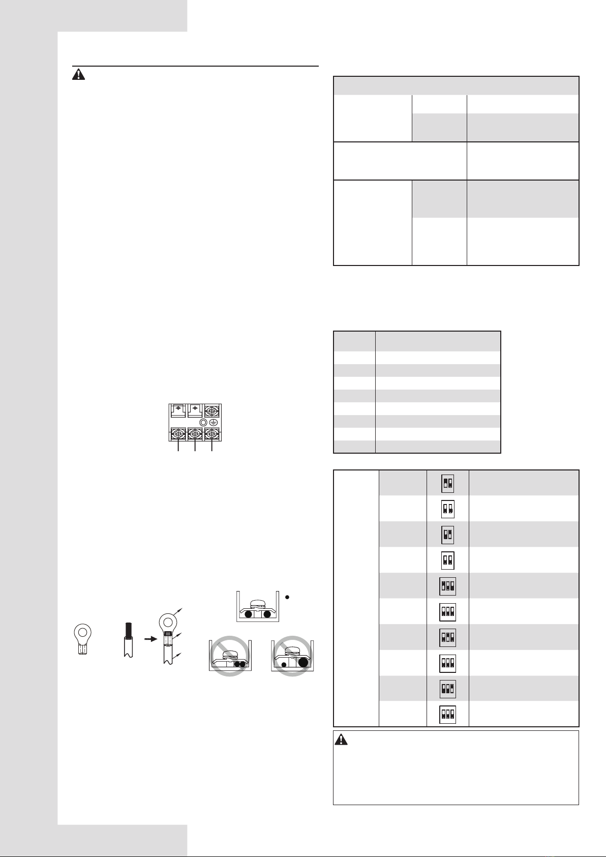
WIRING ....................................................................................... 6
SPECIFICATION PARAMETER ................................................ 10
KRE APPLICATION................................................................... 11
MAINTENANCE AND UPKEEP ................................................ 11
TRAIL RUN................................................................................ 11
ERP INFORMATION. ................................................................ 12
1. PRECAUTIONS
To prevent injury to the user or other people and property
damage, the following instructions must be followed. Incorrect
operation due to ignoring of instructions may cause harm or
damage. The appliance should be installed by a professional in
accordance with the specied instructions.
The safety precautions listed here are divided into two categories. In
either case, important safety informations are listed which must be
read carefully.
WARNING
Failure to observe a warning may cause electric shock,
re hazard or personal injury
CAUTION
Failure to observe a caution may cause injury or damage
to the equipment.
WARNING
● Ask your dealer or qualied personnel to carry out installation
work. Do not try to install the machine by. Incorrect installation
may result in leakage, electric shocks or re.
● Installation should be done by following the installation manual
and no changes should be made to the unit. Incorrect installation
may cause leakage, electric shock, or re. If the KRE falls, it may
cause damage and injury.
● Install the unit on a foundation that is strong enough to withstand
the weight of the unit.
A foundation of insufcient strength may result in the equipment
falling and causing injuries.
● Do not allow exhaust air to enter the outside air inlet.
This may cause the air of the room to become contaminated,
harming the health.
● Locate the outside air intake vent so that it does not take in
exhaust air which contains combustion air, etc.
Incorrect installation may cause a loss of oxygen in the room,
leading to serious accidents.
● Make sure that a separate power supply circuit is provided for
this unit and that all electrical work is carried out by qualied
personnel according to local laws and regulations and this instal-
lation manual.
Insufcient power capacity, improper electrical works, or incorrect
wiring may cause electric shock or re.
● Make sure Earth Leakage Breaker is the type of all poles drop-out.
● Be sure to ground.
Do not connect the ground wire to gas or water pipes, lightning rod
or a telephone ground wire.
Incomplete grounding may result in electric shocks.
● Make sure that all wiring is secured, the specied wires are used,
and no external forces act on the terminal connections or wires.
Improper connections or installation may result in overheating or
fore.
● When wiring the power supply and connecting the remote control-
ler wiring and transmission wiring, position the wires so that the
electric parts box lid can be securely fastened.
Improper positioning of the electric parts box lid may result in
electric shocks, re or the terminals overheating.
CAUTION
● Be sure to install an earth leakage breaker.
Failure to install an earth leakage breaker may result in electric
shocks.
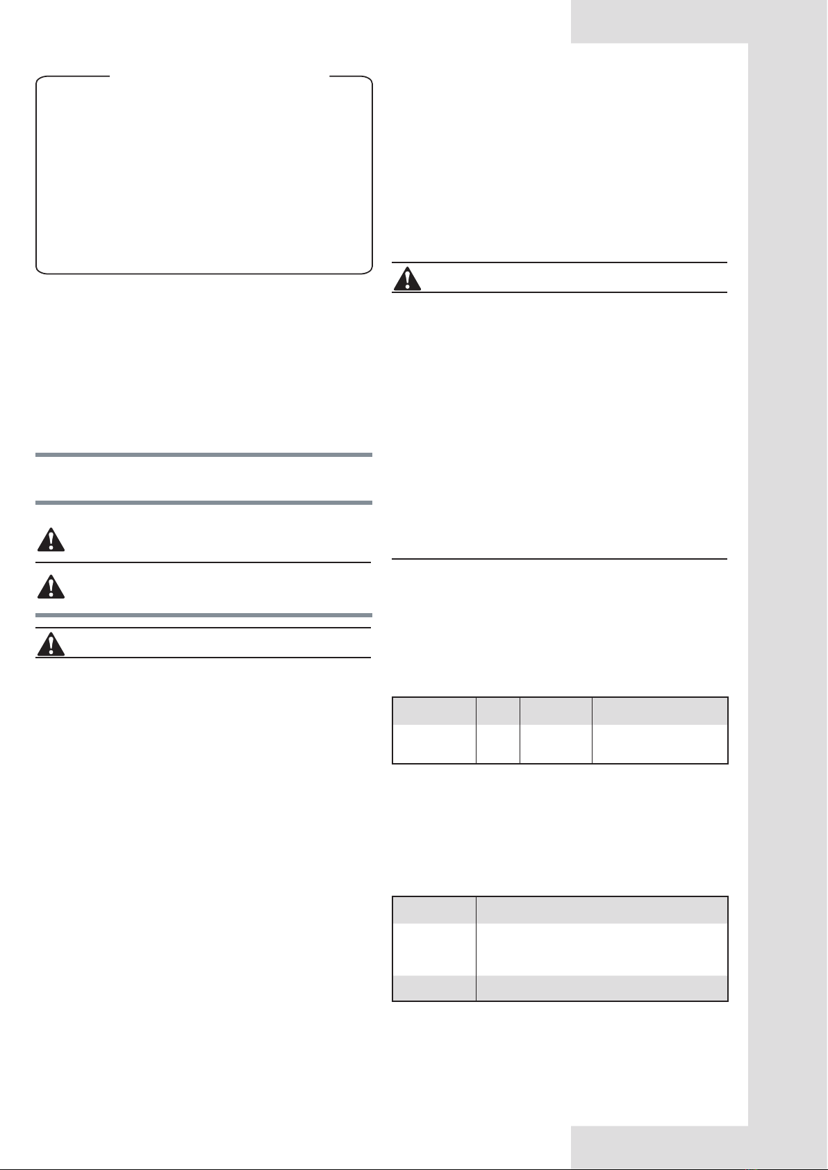
● Install the indoor and outdoor units, power supply wiring and
connecting wires at least 1 meter away from television or radio
in order to prevent image interference or noise. (Depending on
the radio waves, a distance of 1 meter may not be sufcient
enough to eliminate the noise.)
● Install the two outdoor ducts with down slope to prevent rainwa-
ter from entering the unit.
If this is not done completely, water may enter the building, may
damage furniture, etc.
● Insulate the duct and the wall electrically when a metal duct is to
be penetrated through the metal lattice and wire lattice or metal
lining of a wooden structure wall.
Improper duct work may cause electric shocks or short circuits.
● Make sure that a snow protection measure is taken. If no pro-
tection snow may enter through the outdoor ducts, and cause
damaging furniture and electric shock and re.
2. ACCESSORY
Table 2-1
Name Qty. Shape Purpose
Installation and
owner’s manual 1 This manual must be delivered to the
customer
Notes: Wired controller should be purchased separately.
Prepare the following on site.
Table 2-2
Name Purpose
PVC drain pipe
For connecting unit’s drain pipe, which length is
selected according to your actual requirement
(Only required for Model 1500 and 2000
Damper For vibration damping, when lift the unit.

2
3. INSTALLATION
3.1 Installation Preparation
WARNING
Keep all the accessories and tools until installation work is
completed.
● Leave the unit inside its packaging while moving, until reaching
the installation site. Where unpacking is unavoidable, use a sling
of soft material or protective plates together with a rope when
lifting, to avoid damage or scratches to the unit.
● Hold the unit by the hanger brackets when opening the crate and
moving it, and do not lift it holding on to any other part (especially
the duct connecting ange).
NOTE
Be sure to instruct customers how to properly operate the unit
(especially maintenance of air lter, and operation procedure) by
having them carry out operations themselves while looking at the
manual.
3.2 Select The Installation Site
CAUTION
When moving the unit during or after unpacking, make sure to lift
it by holding its hanger brackets. Do not exert any pressure on
other parts, especially duct connecting ange.
● Select an installation site where the following conditions are
fullled and meet with your customer’s approval.
● KRE should be installed far away from ofce, recreation or any
other places where silent environment are required. (install that
in special machine room or wash room is recommended)
● install in a place which has sufcient strength and stability.
(Beam, ceiling and other locations capable of fully supporting
the weight of the unit.) Insufcient strength is dangerous. It may
also cause vibration and unusual operating noise.
● Do not install the unit directly against a ceiling or wall. (If the
unit is in contact with the ceiling or wall, it can cause vibration.)
● Where sufcient clearance for maintenance and service can be
ensured.
CAUTION
● Install the units, power supply wiring and connecting wires at
least 1 meter away from televisions or radios in order to pre-
vent interference or noise. (Depending on the radio waves, a
distance of 1 meter may not be sufcient enough to eliminate
the electric interference.)
● The bellows may not be able to be used in some districts, so
exercise caution. contact your local government ofce or re
department for details.
● When discharging exhaust air to a common duct, the Building
Standard Law requires the use of re proof materials, so
attach a 2m copper plate standing duct.
● Do not install the unit in the following locations:
● Place subjected to high temperature or direct ame. May result in
re or overheating.
● Place such as machinery plant and chemical plate where gas,
which contains noxious gas or corrosive components of materials
such as acid, alkali organic solvent and plaint, is generated.
Place where combus tible gas leakage is likely.
Copper piping and brazed joins may corrode, causing refrigerant
to leak or poisoning and fore due to leaked gas.
● Place such as bathroom subjected to moisture.
Electric leak or electric shocks and other failure can be caused.
● Near machinery emitting electromagnetic waves.
Electromagnetic waves may disturb the operation of the control
system and result in a malfunction of the equipment.
3.3 Preparations Before Installation
● Conrm the positional relationship between the unit and suspen-
sion bolts.
Leave space for servicing the unit and include inspection hatch-
es. (Always open a hole on the side of the electric parts box so
that the air lters, heat exchange elements, fans, be easily be
inspected and serviced.)
● Make sure the range of the unit’s external static pressure is not
exceeded.
● Open the installation hole (Pre-setting ceilings)
Once the installation hole is opened in the ceiling where the unit
is to be installed, pass transmission wiring, and remote controller
wiring to the unit’s wiring holes.
After opening the ceiling hole, make sure ceiling is level if need-
ed. It might be necessary to reinforce the ceiling frame to prevent
shaking.
Please consult architect or woodworker, if necessary.
● Install the suspension bolts. (Use M10 to M12 suspension bolts.)
Use a hole-in anchor, sunken insert anchor for existing ceilings,
or other parts to be procures in the eld to reinforce the ceiling to
bearing the weight of the unit.
● Install vibration damping feet. (For vibration damping)
Wooden structure
Put rectangular sticks across the beams, and set pendant bolts.
Wooden span
Beam
Ceiling
Pendant bolt(M10 to M12)
Old concrete roughcast
Use embedded bolts and embedded pulling plugs.
Fig. 3-1

3
Steel beam and girder structure
Set and use supportive angle steel.
Suspended bolt
Pendant bolt Supportive angle steel
New concrete roughcast
Set it with embedded bushes or embedded bolts.
Concrete iron
Embedded bolt
(With embedded
bolt in pipe)
Flap type inser Slide type inser
Fig. 3-2
3.4 Installation
● Before installation, please conrm all external parts are stand in
their place and without damage.
● The surrounding environment of the unit, especially the sides of
wiring cabinet and water collecting side should reserve sufcient
wiring and maintenance and space; additionally, one should
ensure the removing space for lter griller.
● Unit should mount steadily and without sustain the weight form
condensate water pipe and air duct. The vents of air inlet/outlet
and return should be connected with exible tube.
● Unit in AC 220-240V/50Hz, reliable grounding; each one pos-
sesses of independent cut-off and protection device.
● The installation dimension and maintenance space. (See the
following attached picture Fig.3-3 )
● Operating conditions
For proper performance, run the air conditioner under the following
temperature conditions:
OPERATION
Outdoor air TEMP. -7°C~43°C
Room TEMP. 0°C~43°C
Room humidity
Lower than 80%
If higher than 80%, the surface of indoor
unit may be condensed or the conden-
sate will be blown from air outlet.
Protection or error may occur if running the unit beyond the above
condition, and will cause unit stop running.
H
450
054
1000
400
L
W
Unit : mm
Maintenance space
multiple indoor units (see Figure 7.8);

4
Key dimensions of the unit and air duct installation. (See the following pictures Fig.3-4~3-7 & Table 3-1 )
1
1
+
:
:
/
/
/
:
+
285
/
/
/
1
1
:
+
:
:
+
KRE-500D1~KRE-1000D1
Fig. 3-5
Door
Electric
control
box
Exhaust air outlet Return air inlet
Supply air outlet
Fresh air inlet
By-pass
system
Table 3-1 (Unit:mm)
Model L L1 L2 W1 W2 W H H1 N N1
KRE-500D1 1071 1138 1311 1005 465 1106 390 227 Φ244 195
KRE-1000D1 1071 1138 1311 1431 764 1526 390 230 Φ244 195

5
KRE-1500D1
KRE-2000D1
Fig. 3-6
Fig. 3-7
Door
Door
Return air inlet
Flange dimension
Flange dimension
Supply air outlet
Electric
control
box
Exhaust air
outlet
Fresh air
inlet
Electric
control
box
By-pass
system
Exhaust air
outlet
Fresh air inlet
Return air inlet
Supply air outlet

6
4. WIRING
Warning
● All the supplied parts, materials and electrical works must com-
ply with local regulations.
● Only use copper wires.
● Use a steady power supply for the air-conditioners. The power
voltage must be in line with the rated voltage.
● The electrical wiring works must be carried out by a professional
technician, and must comply with the labels stated in the circuit
diagram.
● Before the electrical connection works are carried out, turn off
the power supply to prevent injuries caused by electric shock.
● The external power supply circuit of the air conditioner must
include an earth line, and the earth line of the power cord
connecting to the indoor unit must be securely connected to the
earth line of the external power supply.
● Leakage protective devices must be congured according to
the local technical standards and requirements for electrical and
electronic devices.
● The xed wiring connected must be equipped with an all-pole
disconnection device with a minimum 3 mm contact separation.
● The distance between the power cord and signal line must be at
least 300 mm to prevent the occurrences of electrical interfer-
ence, malfunction or damage to electrical components. At the
same time, these line must not be in contact with the piping and
valves.
● Choose electrical wiring that conforms to the corresponding
electrical requirements.
● Connect to the power supply only after all the wiring and
connections have been completed, and check carefully if the
connection is correct.
gure of the power supply terminal
POWER INPUT
L
N
Fig. 4-1
When connecting to the power supply terminal, use the circular
wiring terminal with insulation.
Use power cord that conforms to the specications and connect
the power cord rmly. To prevent the cord from being pulled out by
external force, make sure it is xed securely.
If circular wiring terminal with insulation cannot be used, please
make sure that:
• Do not connect two power cords with different diameters to the
same power supply terminal (may cause overheating).
+
:
Circular wiring
terminal
Power
cord
Insulation tube
Copper wire
Proper power wiring connections
Fig. 4-2 Fig. 4-3
4.1 Electric data Specication
Table 4-1
Model KRE-D200~ 2000(B)
Power supply
Phase Single phase
Voltage
/frequency 220-240V/50Hz
Input current
Main switch
/fuse(A)
15/30
Power supply
wireDimension
Wire’s qty
3 (Earthing line
should be used
yellow/green wire.)
Wire
cross
-section
(mm2)
2.5
● After wiring, please conrm all connections are correct, and then
power to the unit.
● Pay attention to the power supply wire of three-phase model;
conrm the phase sequence of which is correct.
Table 4-2
ENC1 Settings for Capacity SW1 Setting for static pressure
ENC1 Capacity setting
0 200
1 300
2400
3 500
4800
5 1000
6 1500
7 2000
SW1-1
ON
12
ON
Low static pressure
OFF
12
ON
High static pressure
SW1-2
ON
12
ON
KRE centralized control
OFF
12
ON
KRE single unit operation
SW2-1
ON
12
ON
3
With PRO
OFF
12
ON
3
Without PRO
SW2-2
ON
12
ON
3
Positive Pressure
OFF
12
ON
3
Negative Pressure
SW2-3
ON
13
ON
2
SW2 -2
OFF
12
ON
3
Balance Pressure
Caution
• Positive Pressure: In the positive pressure mode, the supply
fan operating fan speed is higher than the exhaust fan.
• Negative Pressure: In the negative pressure mode, the exhaust
fan operating fan speed is higher than the supply fan.
• Balance Pressure: In the balance pressure mode, the supply
fan operating wind gear is equal to the exhaust fan.

7
Table 4-3 Code and Denitions
Operation lamp Flashing
times
Show on central-
ized controller
Explanation
●/ / Unit is ON
○/ / Unit is OFF
★E2 Indoor temperature sensor
error
★4E5(new protocol)
EF(old protocol)
Outdoor temperature sensor
error
★6 E7 EEPROM error
★8 E6 DC fan motor error
★10 OFF LINE Without address
★12 E1 Communication error with
ODU
★14 Ip address Conict
★16 EU error with sensor board
★18 FC error with CO2 sensor
E9 wire controller communica-
tion failure
Ed Outdoor unit failure
NOTE: ●:Light ; ○:Extinguish ; ★:Quick ash
Table 4-4 Terminal Denition
CODE CN8 CN9 CN32 CN33 CN7 CN3 CN4 CN21
NAME P Q E X Y E Modbus RTU D1D2E X1X2 Indoor temp. Sensor Outdoor temp. Sensor PRO
Dry contact
(In put)
CN31 Inlet air pre-heat Signal
CN16 Force to exhaust air mode
CN26 Remote ON/OFF
Dry contact
(Out put)
CN14 Signal for ventilation fan
CN15 Alarm
CN20 Signal for inlet air Pre-heat
Communication wiring between the indoor and outdoor units
The KRE and outdoor units communicate via the RS485 serial port.
The communication wiring between the KRE and outdoor units should be connected one unit after another in a daisy chain from the out-
door unit to the nal KRE unit. And the shielded layer must be properly grounded, and a build-out resistor must be added to the last KRE
unit to enhance the stability of the communication system.
Incorrect wiring such as a star connection or a closed ring will cause instability of the communication system and system control anoma-
lies.
Use a three core shielded wire (greater than or equal to 0.75 mm2) for the communication wiring between the indoor and outdoor units.
Make sure the wiring is connected correctly. The connecting lead for this communication wire must come from the master outdoor unit.
All shielded wiring in the network are interconnected, and will eventually connect to earth at the same point “ ”.
P
Q
Outdoor
unit (Connect the shielded end of the shielded wire to
the electronic controller box sheet metal " " here)
Signalling line be-
tween outdoor units
Connecting the shielded
layer of the shielded wire
Only the last indoor unit requires add-
ing the build-out resistor at P and Q.
(open)
Indoor and out-
door units Com-
munication wire
Build-out
resistor
(P Q E)
(P Q E)

8
Communication wiring between the indoor unit and wired controller
The wired controller and the indoor unit can be connected in different manners, depending on the forms of communication.
1. For a bidirectional communication mode:
● Use 1 wired controller to control 1 indoor unit or 2 wired controllers (one master and one slave controller) to control 1 indoor unit.(see
Fig.4-4)
● Use 1 wired controller to control multiple indoor units or 2 wired controllers (one master and one slave controller) to control multiple
indoor units. The maximum number of connections is 16.(see Fig.4-5)
2. For single direction communication mode:
● Use 1 wired controller to control 1 indoor unit
● The X1/X2, D1/D2 ports on the sides of the main control board and single direction communication port are for different types of wired
controllers.
● For the specic connection method, refer to the instructions in the corresponding wired controller manual to carry out the wiring and
connections.
Handling the Electrical Wiring Connection Points
● Once the wiring and connections are done, use tie straps to secure the wiring properly so that the connection joint cannot be pulled apart
by external force. The connection wiring must be straight out so that the cover of the electrical box is level and can be closed tightly.
● Use professional insulation and sealing materials to seal and protect the perforated wires. Poor sealing may lead to condensation, and
entry of small animals and insects that may cause short circuits in parts of the electrical system, causing the system to fail.
X1 X2
X1 X2
X1 X2
X2 X1 D2 D1
X2 X1 D2 D1
X1 X2 X1 X2 X1 X2
XD1
TXR
PQX
ED2
EY EE D1
T
T
XX
XR
PQX
ED2
EY EE
D1
X
XR
PQX
ED2
EY EE
D1
TXR
PQX
ED2
EY EE
Fig. 4-4
Indoor unit 1
Wired controller 1
Master wired controller
Wired controller 1 Wired controller 2
Master wired controller Slave wired controller
Indoor unit 1 Indoor unit 2 Indoor unit n(n<=16)
Slave wired controller
Wired controller 2
Fig. 4-5
Operatio Manual
There are two types of precautions as described below:
Warning: Failure to comply may lead to serious injury.
Caution: Failure to comply may lead to injury or damage of the
unit. Depending on the situation, this may also lead to serious injury.
Once the installation is completed, please keep the manual properly
for future reference. When this air conditioner is handed over to oth-
er users, make sure that the manual is included with the handover.
Warning
• Do not use this unit in locations where ammable gas may exist.
If ammable gas comes into contact with the unit, a re may
occur, which could result in serious injury.
• If this unit exhibits any abnormal behavior (such as emitting
smoke) there is a danger of serious injury. Disconnect the power
supply and contact your supplier or service engineer immediate-
ly.
• The refrigerant in this unit is safe and should not leak if the
system is designed and installed properly. However, if a large
amount of refrigerant leaks into a room, the oxygen concentra-
tion will decrease rapidly, which can cause serious injury. The
refrigerant used in this unit is heavier than air, so the danger is
greater in basements or other underground spaces. In the event
of a refrigerant leak, turn off any devices that produce a naked
ame and any heating devices, ventilate the room, and contact
your supplier or service engineer immediately.
• Toxic fumes may be produced if the refrigerant in this unit
comes into contact with naked ames (such as from a heater,
gas stove/burners, or electric appliances).

9
• If this unit is used in the same room as a cooker, stove, hob, or
burner, ventilation for sufcient fresh air must be ensured, other-
wise the oxygen concentration will fall, which may cause injury.
• Dispose of this unit’s packaging carefully, so children cann’t play
with it. Packaging, especially plastic packaging, can be danger-
ous, can cause serious injury. Screws, staples and other metal
packaging components can be sharp and should be disposed of
carefully to avoid injury.
• Dispose of this unit’s packaging carefully, so children cann’t play
with it. Packaging, especially plastic packaging, can be danger-
ous, can cause serious injury. Screws, staples and other metal
packaging components can be sharp and should be disposed of
carefully to avoid injury.
• Do not attempt to inspect or repair this unit yourself. This unit
should only be serviced and maintained by a professional air
conditioning service engineer. Incorrect servicing or mainte-
nance can cause electric shocks, re or water leaks.
• This unit should only be re-positioned or re-installed by a
professional technician. Incorrect installation can lead to electric
shocks, re or water leaks. The installation and grounding of
electrical appliances should only be carried out by licensed pro-
fessionals. Ask your supplier or installation engineer for further
information.
• Do not allow this unit or its remote controller to come into con-
tact with water, as this can lead to electric shocks or re.
• Turn off the unit before cleaning it to avoid electric shocks.
Otherwise, an electric shock and injury may result.
• To avoid electric shocks and res, install an earth leakage de-
tector.
• Do not use paint, varnish, hair spray, other ammable sprays or
other liquids that may give off ammable fumes/vapor near this
unit, as doing so can cause res.
• When replacing a fuse, ensure that the new fuse to be installed
completely complies with requirements.
• Do not open or remove the unit’s panel when the unit is pow-
ered on. Touching the unit’s internal components while the unit
is powered on can lead to electric shocks or injuries caused by
moving parts such as the unit’s fan.
• Ensure that the power supply is disconnected before any servic-
ing or maintenance is carried out.
• Do not touch the unit or its remote controller with wet hands, as
doing so can lead to electric shocks.
• Do not allow children to play near this unit, as doing so risks
injury.
• Do not insert your ngers or other objects into the unit’s air inlet
or air outlet to avoid injury or damage to the equipment.
• Do not spray any liquids onto the unit or allow any liquids to drip
onto the unit.
• Do not place vases or other liquid containers on the unit or in
places where liquid could drip onto it. Water or other liquids that
come into contact with the unit can lead to electric shocks or
res.
• Do not remove the remote controller’s front or back overs and
do not touch the remote controller’s internal components, as
doing so can cause injury. If the remote controller stops working,
contact your supplier or service engineer.
• Ensure that the unit is properly grounded, otherwise electric
shocks or a re may result. Electrical surges (such as those that
can be caused by lightning) can damage electrical equipment.
Ensure that suitable surge protectors and circuit breakers are
properly installed, otherwise electric shocks or a re may result.
• Dispose of this unit properly and in accordance with regulations.
If electrical appliances are disposed of in landlls or dumps,
hazardous substances can leak into the groundwater and thus
enter the food chain.
• Do not use the unit until the qualied technician instructs you
that it is safe to do so.
• Do not place appliances that produce naked ames in the
path of the airow from the unit. The airow from the unit may
increase the rate of combustion, which may cause a re and
cause serious injury. Alternatively, the airow may cause incom-
plete combustion which can lead to reduced oxygen concentra-
tion in the room, which can cause serious injury.
Caution
• Only use the air conditioner for its intended purpose. This unit
should not be used to provide refrigeration or cooling for food,
plants, animals, machinery, equipment or art.
• Do not insert your ngers or other objects into the unit’s air inlet
or air outlet to avoid injury or damage to the equipment.
• The ns on the unit’s heat exchanger are sharp and can cause
injury if touched. To prevent injury, when the unit is being ser-
viced, gloves should be worn or the heat exchanger should be
covered.
• Do not place items which might be damaged by moisture under
the unit. When the humidity is greater than 80% or if the drain
pipe is blocked or the air lter is dirty, water could drip from the
unit and damage objects placed under the unit.
• Ensure that the drain pipe functions properly. If the drain pipe
is blocked by dirt or dust, water leaks may occur when the unit
is running in cooling mode. If this happens, turn the unit off and
contact your supplier or service engineer.
• Do not touch the internal parts of the controller. Do not remove
the front panel. Some internal parts may cause injury or be
damaged.
• Ensure that children, plants and animals are not directly ex-
posed to the airow from the unit.
• When fumigating a room with insecticide or other chemicals,
cover the unit well and do not run it. Failure to observe this
caution could lead to chemicals getting deposited inside the unit
and later emitted from the unit when it running, endangering the
health of any room occupants.
• Do not dispose of this product as unsorted waste. It must be
separately collected and processed. Ensure that all applicable
legislation regarding the disposal of refrigerant, oil and other
materials is adhered to. Contact your local waste disposal au-
thorty for information about disposal procedures.
• To avoid damaging the remote controller, exercise caution when
using it and replacing its batteries. Do not place objects on top
of it.
• Do not place appliances that have naked ames under or near
the unit, as heat from the appliance can damage the unit.
• Do not place the unit’s remote controller in direct sunlight. Direct
sunlight can damage the remote controller’s display.
• Do not use strong chemical cleaners to clean the unit, as doing
so can damage the unit’s display or other surfaces. If the unit
is dirty or dusty, use a slightly damp cloth with very diluted and
mild detergent to wipe the unit. Then, dry it with a dry cloth.
• Children shall not play with the appliance.
CAUTION
1. Never turn screws too tightly, or else the cover would be dented or the Liquid Crystal breaks.
2. Please leave sufcient space for maintenance and service of wired controller.
3. Wired controller should be purchased separately.
4. Please follow the installation and owner’s manual of wired controller.

10
5. SPECIFICATION PARAMETER
5.1 Specication Parameter
Table 5-1
Model Power supply Packing size(mm) Air outlet dimen-
sion (mm)
Net weight
(kg)
Static pres-
sure (Pa)
Nominal air
ow (m3/h)
KRE-500D1
220-240V~
50Hz
1390×1244×540 Φ244 74.4 90 500
KRE-1000D1 1390×1670×540 Φ244 90 160 1000
KRE-1500D1 1830×1520×770 346×326 181.5 180 1500
KRE-2000D1 1900×1720×845 346×326 208.5 200 2000
Table 5-2
Model Nominal temp.
efciency
Nominal enthalpy
efciency
Sound power
level(dB)
Power input(kW) Current(A)
KRE-500D1 80.6 74.0 50 0.15 1.2
KRE-1000D1 82.8 76.0 54 0.38 2.9
KRE-1500D1 75.5 69.4 69 0.68 3.8
KRE-2000D1 77.2 74.7 70 0.95 5.7
Notes:
There are 3 steps of fan speed (High, Medium, Low), all the parameters
in the above table is measured at the high speed.

11
6. KRE APPLICATION
6.1 Operation principle
KRE (Heat Recovery Ventilation) employ advanced technique
and technics, the heat exchanged core forming by special paper
that be processed with chemical treatment, which could create
the optimum result in temperature, humidity and cooling recov-
ery.
High efciency heat exchanged core: When air ow formed by
exhaust air and outdoor air through the heat exchanged core in
cross way, because of temperature difference in the two sides
of at partition board, the heat transmission is occurred. In
summer, outdoor air acquire cooling from air exhaust to decrease
environment temperature; In winter, outdoor air acquire heat from
air exhaust to increase temperature, that is to say, it realizing the
energy recovery during air exhaust process to exchange the heat
in heat exchanged core to outdoor air.
6.2 Pay Attention To The Following Items Before
Operation
6.2.1. Before start-up, please clean up the duct and check
whether all air valves and devices are normal.
6.2.2. Carefully adjust the system air valves when start-up, con-
trol the current of motor in rated range.
6.2.3. Three-phase model without by-pass function, therefore the
fan would delay 30 seconds to start up.
6.2.4. Connect the wired controller
Wired controller should be installed according to wired
controller owner’s manual, installation manual (Attached in
the package box in wire controller).
7 MAINTENANCE AND UPKEEP
7.1 During early use, one should check the fan operation regu-
larly.
7.2 The cleaning regulation for air lter depend on local environ-
ment. It could be clean by vacuum dirt exhauster or water, if
heavy dust accumulates, it should use neutral detergent to
clean it, and then dry it in shady and cool place for 20 to 30
minutes and replace it.
7.3 Clean the core at least 2 years a time by vacuum dirt
exhauster to remove dust and foreign substance in the unit
assemblies, do not touch the assemblies by exhauster and
ush by water to avoid core damage.
7.4 Check the fan every half a year to maintain the well balance
of it and check whether the axletree has loosed.
8. TRIAL RUN
8.1 Please Conrm The Following Points Before
Trial Run:
8.1.1 The unit is installed correctly completed.
8.1.2 Ducting and wiring are correctly completed.
8.1.3 The drainage is smooth.
8.1.4 The heating insulation works well.
8.1.5 The ground wiring is connected correctly.
8.1.6 The power voltage ts the rated voltage of KRE.
8.1.7 There is no obstacle at the outlet and inlet of KRE.
8.2 Control The KRE By Wired controller, Operate
It According To Wired controller Owner’s Manual.
8.2.1 Whether the switch on the remote controller works well.
8.2.2 Whether the room temperature is adjusted well.
8.2.3 Whether the indicator lights normally.
8.2.4 Whether there is vibration or abnormal noise during opera-
tion.

12
9. ERP INFORMATION
Table 9-1
Fan Types Centrifugal forward curved fan
Directive (or Standard) for Regulation ErP Directive 2009/125/EC
COMMISSION REGULATION (EU) No 327/2011
Model Name WZDK170-38G-2 +LX-245*203*12-
48J 1320
Rev.
Prepare by
Specied Information of Fan:
No. Information Item Comment
1ηtarget= 32.5%
2Overall efciencye(ηe)= 33.02%
3Pass or not (Criteria:ηe≥ηtarget) Pass
4Measurement category (A -D) A
5Efciency category (static or total) Static
6Efciency grade at optimum energy efciency point N =44.52
7 VSD is integrated within the fan YES
8 Year of Manufacture Ref. to the Unit Nameplate
9 Manufacturer’s name and place of manufacture Ref. to the Unit Nameplate
10.1 Rated motor power input(s) (kW), at optimum energy efciency 0.1517 kw
10.2 Rated motor ow rate(s) at optimum energy efciency 0.1614m3/s
10.3 Rated motor pressure(s) at optimum energy efciency 270 Pa
11 Rotations per minute (R.P.M)at the optimum energy efciency
point
1320r/min
12 Specic ratio 1.001
13 Information relevant for facilitating disassembly, recycling or
disposal at end-of-life
all materials can be recycled
14 Information relevant to minimize impact on the environment
and ensure optimal life expectancy as regards installation, use
and maintenance of the fan
For installation, the clearance of 500 mm
shall be kept from inlet
15 Description of additional items used when determining the fan
energy efciency,such as ducts, that are not described in the
measurement category and supplied with the fan.
Measurement category A, fan is free inlet
and outlet conditions
16 Motor manufacturer NIDEC
SHIBAURA(ZHEJIANG)CORP.

13
Table 9-2
Fan Types Centrifugal forward curved fan
Directive (or Standard) for Regulation ErP Directive 2009/125/EC
COMMISSION REGULATION (EU) No 327/2011
Model
Name
WZDK750-38G-W-1+LX-261*234*15
-48J 1300
Rev.
Prepare by
Specied Information of Fan:
No. Information Item Comment
1ηtarget=34.14%
2Overall efciencye(ηe)= 49.7%
3Pass or not (Criteria:ηe≥ηtarget) Pass
4Measurement category (A -D) A
5Efciency category (static or total) Static
6Efciency grade at optimum energy efciency point N =59.51
7 VSD is integrated within the fan YES
8 Year of Manufacture Ref. to the Unit Nameplate
9 Manufacturer’s name and place of manufacture Ref. to the Unit Nameplate
10.1 Rated motor power input(s) (kW), at optimum energy efciency 0.276 kw
10.2 Rated motor ow rate(s) at optimum energy efciency 0.34m3/s
10.3 Rated motor pressure(s) at optimum energy efciency 360 Pa
11 Rotations per minute (R.P.M)at the optimum energy efciency
point 1300r/min
12 Specic ratio 1.001
13 Information relevant for facilitating disassembly, recycling or
disposal at end-of-life All materials can be recycled
14
Information relevant to minimize impact on the environment
and ensure optimal life expectancy as regards installation, use
and maintenance of the fan
For installation, the clearance of 500 mm
shall be kept from inlet
15
Description of additional items used when determining the fan
energy efciency,such as ducts, that are not described in the
measurement category and supplied with the fan.
Measurement category A, fan is free inlet
and outlet conditions
16 Motor manufacturer Panasonic Appliances Motor(Hangzhou)
Co.Ltd.

14
Table 9-3 Required information for RVU in COMMISSION REGULATION (EU) No.1254/2014 ANNEX IV
No. Information Item Comment
1 Supplier's name Kaysun
2 Model name KRE-500D1 KRE-1000D1 KRE-1500D1 KRE-2000D1
3 Declared typology NRVU,BVU NRVU,BVU NRVU,BVU NRVU,BVU
4Type of drive Multi-speed Multi-speed Multi-speed Multi-speed
5 Type of HRS Other Other Other Other
6Thermal efciency(%) 80.6 82.8 75.5 77.2
7Nominal ow rate(m3/s) 0.139 0.278 0.417 0.556
8 Electric power input(kW) 0.157 0.383 0.677 0.956
9 SFPint(W/(m3/h)) 682 785 702 730
10 Face velocity(m/s) 0.66 0.87 1.0 1.0
11 Nominal external pressure(Pa) 96 160 180 200
12 Internal pressure drop(Pa) 189 384 253 322
13 Internal pressure drop ofnon-ventilation
components(Pa) - - - -
14 Efciency in Regulation (EU) NO 327/2011 Out of scope 33 49.7 49.7
15 Maximum leakage rate(%) 10 0r less 10 0r less 10 0r less 10 0r less
16 Energy classication of thelters - - - -
17 Visual lter warning Refer to instruction book
18 Casingsound power level(dB) 50 54 69 70

15
16126100000189 V4.0

This manual suits for next models
3
Table of contents
Other Kaysun Air Cleaner manuals