Tecnoinox GD4FG9 User manual

GD4FG9
FREESTANDING GAS GRILL WITH WATER AND CA ST IRON GRID ON CLOSED
CABINET
333112
CODE
DESCRIPTION
MODEL
03-03-2023 12:30
EN - 1
5410.495.01
Part 1
Installation
DIRECT OR LAVA STONE GRILL
General warnings
The appliance described in this manual was
manufactured in compliance with the
standards. This appliance is intended only for
cooking food professionally and must be used
by qualified personnel. Any other use is
improper.
The appliance must be used only under
surveillance. Moreover, the appliance should
be checked once a year by a qualified
technician.
Switch the appliance off in the event of a fault
or malfunction.
Care must be taken when using the appliance because the tank and the cooking surfaces are
very hot.
The appliance must be installed, connected and serviced by qualified personnel according to
the regulations and directives in force in the country where it is installed, as well
as the
instructions in this manual.
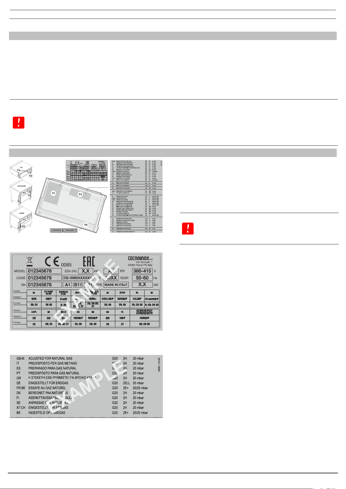
Characteristics of the appliance
The serial number plate “T1” (fig.1) is behind the control panel
(inside the appliance). This plate contains the following data:
The supplementary plate is also made of self-adhesive polyester
and is affixed near the data plate; it contains all information
regarding the appliance arrangement.
The supplementary plate is also made of self-adhesive polyester
and is affixed near the data plate; it contains all information
regarding the appliance arrangement.
Appliances measuring 35 cm or 40 cm wide are equipped with a
burner and a gas connection fitting. Appliances measuring 70 cm
or 80 cm wide are equipped with two burners and a gas
connection fitting.
The gas distribution network fitting meets EN10226-1 standards
and is situated on the back of the appliance. The appliance
structure is made of stainless steel and the burners are made of
steel.
All models have height-adjustable feet.
The main gas pipe is made of galvanised steel. The pipes between
the shut-off cock and the burner are made of copper.
Place a shut-off valve between the
appliance and the gas distribution
network.

EN - 2
5410.495.01
Connecting to the distribution network
Before you install the appliance, make
sure that the gas supp
lier company has
authorised the installation,
subsequently compare the appliance
data (data plate) with the local supply.
Remove the appliance packaging as well as the protective plastic
sheet. If necessary, remove any glue with a suitable solvent. For
information on disposing of the packaging, please consult the
local regulations in force (for more details, please refer to the
chapter “ECOLOGY AND THE ENVIRONMENT”. Prior to connecting
the unit to the gas network, check the data plate to see if the unit
has been set and tested for the type of gas available. If the gas
type indicated on the data plate is not the same as that supplied,
please refer to the section “CONVERSION AND ADAPTATION”.
Connect the appliance to the gas distribution network using
metal pipes with a suitable diameter and interposing an
approved shut-off valve. Flexible pipes can be used, provided that
they are made of stainless steel in compliance with the
regulations in force. When installing the appliance, all the
regulations in force must be observed such as
Safety standards.
Regional and/or local regulations such as building regulations.
Accident-prevention regulations in force.
Fire-prevention regulations.
Applicable IEC regulations (only in Italy).
We recommend installing the appliance in a well-ventilated
environment, or under an extractor hood in order to remove the
fumes or steam produced during cooking. The appliance has an
equipotential earth terminal at the back “ ” (fig.1). The appliance
can be installed as a standalone unit or in combination with other
appliances. Keep a minimum distance of 80 mm between the
appliance and any walls made of flammable material, partitions,
kitchen furniture or adjacent equipment. The adjacent surfaces
must be covered with non-combustible heat-insulating material.
Once the appliance is installed, check the seal of the fittings. To
detect any leaks, use non-corrosive foam-based products such as
a leak-detection spray.
Do not use naked flames during the leak test.
The manufacturer is not responsible for damage resulting from failure to comply with the
installation and use instructions or improper use. Moreover, the manufacturer is not
responsible for connections made that do not comply with the regulations in force and fire-
prevention provisions.
Evacuating unburned gases
This appliance belongs to construction type classification A1, therefore connection to a flue is not necessary.
Checking the pressure
The mains pressure must comply with the
values reported in the nozzle table
according to the type of gas supplied.
shown above, please inform your utility company. Do not start up
the appliance until the cause has been found and the problem
solved.
The distribution network pressure can be taken using a U-tube
manometer (min. value 0.1 mbar), connected to the pressure
outlet at the base of the appliance “P” (fig.6).
1. Remove the screw and sealing washer “Y” (fig.6) from the
pressure outlet and connect the manometer.
2. Turn the appliance on following the enclosed instructions
and check that the pressure is within the permitted pressure
range.
3. Disconnect the manometer and replace the screw “Y” (fig.6)
and the sealing washer in the pressure outlet.

EN - 3
5410.495.01
Part 2
Conversion and adaptation
Changing the gas supply - Conversion
If the gas supply to the room where the appliance is to
be installed is different from the gas it is set up for, the
appliance must be converted from one type of gas to
another, e.g. from natural gas to LPG. In this case, the
nozzles of the main burner, the by-pass and the pilot
light need to be changed.
All the nozzles are marked with a number that indicates the
diameter in 1/100, and are supplied in a bag.
After each conversion or adaptation, the appliance must
undergo an operating test and the supplementary plate
must be updated according to the conversion or
adaptation carried out.
All appliance connection, installation and maintenance operations must only be carried out by
qualified technicians and in compliance with all applicable regulations.
For further details refer to the nozzle table.
Replacing the nozzles and adjusting the air
BURNER:
Detach the knobs.
Remove the control panel by unscrewing the fixing
screws at the bottom.
Replace the nozzles (fig.5) with suitable ones for the
new type of gas indicated in the nozzles table section
“Technical data”.
ADJUSTING THE AIRFLOW:
Unscrew the fixing screw on the primary air adjustment
bush.
Move the bush the distance “H” (fig.7). indicated in the
nozzles table
Block the bush by tightening its fixing screw. PILOT:
Unscrew and remove the closing nut (fig.3).
Replace or adjust the pilot nozzle “D” (fig.3) as per the
indications in the nozzles table.
Refit the closing nut.
MINIMUM:
Replace or adjust the minimum nozzle “Um” (fig.6) as
indicated in the nozzles table.
Reassemble the panel and the knobs.
EN - 4
5410.495.01
Part 3
Use
Fat recovery drawer
Before operating the appliance and
starting cooking, always fill any recovery
tank(s) “V
” (fig.2) with clean water. Do
not use the appliance with empty tanks;
the tanks must always hold a minimum
of 2 litres of water.
After cooking or at the end of the day
and only after the appliance has cooled
down, empty the tanks “V” (fig.2).
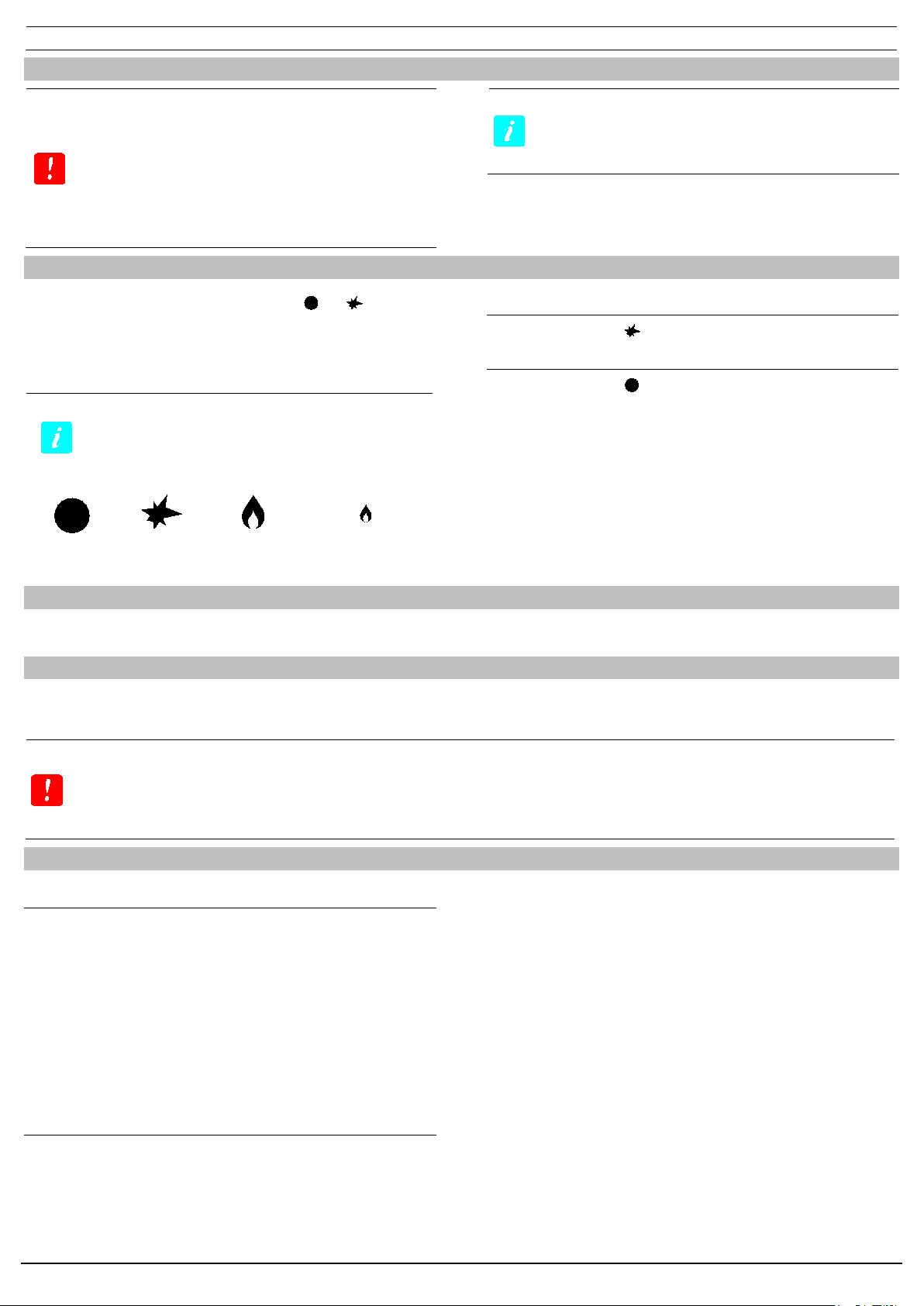
Turning on the burner and the appliance
Press and turn knob “A” (fig.4) from position “ ” to “ ”. At the
same time press ignition button “B” (fig.4) repeatedly to light the
pilot light. After the flame has lit, hold the knob down for roughly
10 seconds (count to 20), so the thermocouple heats up and
keeps the safety valve open.
If the piezoelectric device cannot be
u
sed, you can manually light the
flame using a match or a gas lighter.
Off Flame on pilot
light Burner max Burner min
TURNING THE BURNER OFF
Turn the knob to the “ ” position.
TURNING THE APPLIANCE OFF
Turn the knob to the “ ” position.
What to do when the appliance is not going to be used for a long time
Close the gas shut-off cock. Clean the appliance with soapy water, rinse it, dry it thoroughly
and apply a light layer of liquid paraffin.
What to do in the event of a malfunction
Malfunctions are not always caused by the quality of the
components used. These appliances are manufactured using top
quality components.
Failures may be caused by dust and dirt infiltrating the operating
components.
Unauthorised persons should never attempt to repair the appliance or carry out maintenance.
Tampering with the appliance voids the warranty.
If you suspect that there may be a fault, close the shut-off cock and inform the authorised
support service
.
Operational checks
THERMAL CAPACITY
Check that the gas type and group where the unit is to be used is
the same as that indicated on the plate. If it is not, follow the
conversion or adaptation procedure in the section “Conversion
and adaptation”.
Check that the right nozzles have been installed. Refer to the
nozzle table and check that the nozzles indicated in the table are
the same as those installed on the unit. As an additional check of
the thermal capacity, verify the gas consumed using the
volumetric method: start the burner and, after approximately 10
minutes (in working conditions), check that the gas flow (in m3/h
or in kg/h) corresponds to that in the nozzles table.
FLAME APPEARANCE AND PRIMARY AIRFLOW
Use the inspection hole “I” (fig.2) to check the flame.
The flame should be blue and there should be no yellow dots in
it; it must be stable at the base. If the colour of the flame is yellow,
it means the primary airflow is not adjusted properly. If the
primary airflow is too fast, the flame will be short and tend to burn
above the burner. The primary air capacity is fixed, therefore no
adjustment is required. The appearance of the flame must also be
checked 15 minutes after the appliance has been running at full
power. The flame must remain stable even when passing quickly
from minimum to maximum.
Any alterations made to the installation area
which may influence the amount of air needed
for combustion require appliance operation to
be checked again. When these checks have
been completed, test the appliance for leaks.

EN - 5
5410.495.01
Replacing parts
Faulty parts should only be replaced by
qualified personnel.
Disconnect the appliance from the gas
distribution network before doing any work.
After having removed the control panel, all the functional parts of
the appliance are easily accessible.
Only order spare parts from the
manufacturer or an authorised dealer.

EN - 6
5410.495.01
Part 4
Maintenance and cleaning
Cleaning and care
Cleaning operations must only be
carried out once the appliance has
cooled.
Only use products that are food safe.
To clean the appliance, disassemble it as per the steps shown in
figs “14” to “18”.
Keeping the appliance clean is very important for a long and
trouble-free product life. Wash the removable parts separately
with warm water and detergent, then rinse them under running
water. Do not use harsh or abrasive detergents to clean the
stainless steel parts. Iron cleaning pads should not be used as
they may cause rust to form. For the same reason, avoid contact
with ferrous materials.
When cleaning, avoid using abrasive paper or cloth; instead, and
only in special cases, use pumice stone powder. For stubborn
deposits, use a sponge (e.g. Scotch-Brite). You can also use oven
and grill cleaning sprays, readily available on the market, to
remove stubborn deposits.
If you use spray products, please follow the manufacturer’s
instructions.
To minimise emissions of polluting substances into the
environment, clean the appliance with products that are at least
90% biodegradable.
Additional recommendations for cleaning, for gas grills only
Before turning on the appliance, frequent checks and cleaning of the inside of the appliance
are recommended. This is to prevent oil and grease residues from previous cooking being
burned.
For lava stone grills:
•Clean the burner holes regularly with a metal brush to prevent clogging and promote
good combustion;
•Remember that the lava stones must be distributed on the metal grid as uniformly as
possible, noting the following amounts:
GR35G/G6 - GR35G/0 - GR35G7
GR70G/G6 – GR70G/0 - GR70G7
3.3kg
6.6kg
EN - 7
5410.495.01
FAULTS
Malfunctions are not always explained by the quality of the
components used. These appliances are manufactured using top
quality components. Malfunctions may be caused by voltage
surges, or by dust or dirt infiltrating the components. If you
suspect that there may be a fault, ALWAYS turn the appliance off
and call the authorised support service.
These appliances are manufactured using high-quality
components. Malfunctions may be caused by voltage surges,
dust and/or dirt infiltrating the components.
Unauthorised persons should never
attempt to repair the appliance or carry out
maintenance. Tampering with the appliance
voids the warranty.
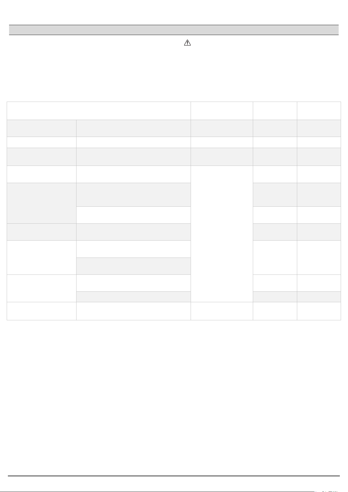
MAINTENANCE – TESTS – CHECKS – CLEANING FREQUENCY USER SUPPORT
SERVICE
Cleaning General cleaning of the appliance and the
surrounding areas
Daily or based on the
degree of use Yes -
Safety devices Check the safety devices function correctly Monthly Yes Yes
Mechanical protective
devices
Check condition. Check that there are no
deformations or loose/missing parts. Monthly Yes Yes
Controls Check the readability and condition of the
inscriptions and symbols. Repair if necessary.
Yearly
Yes Yes
Appliance structure
Check the mechanical part to make sure that
it is not broken or deformed. Check the screws
are tightened.
Yes Yes
Tighten the main bolts (screws, fasteners, etc.)
on the appliance - Yes
Safety signs Check the readability and condition of the
safety signs. Yes Yes
Electrical control panel /
electronics
Check the condition of the electrical parts
installed on the electrical control panel. - Yes
Check the wiring between the electrical panel
and the parts of the appliance.
Electrical connection
cable and plug socket
Check the condition of the connection cable
and plug socket. Yes Yes
Replace if defective. - Yes
Motor bearings (if
present) Replace motor bearings Every three years - Yes
EN - 8
5410.495.01
Safety precautions
REMEMBER THAT THE APPLIANCE
The appliance must never be left
unattended when in use.
When the unit is switched on, the surfaces
get very hot. Please take great care.
The appliance is intended for professional
use and therefore only qualified personnel
should use it.
Installation, as well as any conversion or
adaptation operations to a different gas
type, must be carried out in accordance
with current laws and only by qualified,
authorised personnel.
At least once a year, have the appliance
checked by qualified personnel.
All the parts that come into contact with oil
or fat during use should be cleaned
regularly, as indicated in the chapter
“Cleaning and Care”.
In the event of a fire, close the shut-off
cock immediately to cut off the gas
supply, then use a suitable fire
extinguisher.
Ecology and environment
Our appliances are studied and optimised via testing to provide
high performance and yields. To reduce energy consumption
(electricity, gas and water), do not use the appliance for long
periods of time without food inside or in conditions that may
compromise optimum yield.
All of the following materials are used for the packaging:
•Polyethylene: external packaging film and/or bubble wrap
•Polypropylene: straps
•Expanded polystyrene: corner pieces, protective sheets and
blocks
•Cardboard
•Wooden base frame
These materials are environmentally friendly and can be safely
stored or reused/recycled. Should you wish to dispose of them,
please adhere to the waste regulations in force in your country.
Dispose of the appliance responsibly at the end of its useful life.
In compliance with the regulations in force in your
country, dispose of the waste product by taking it
to an authorised collection and treatment site, after
removing the power cable.
This manual suits for next models
1
Table of contents
Other Tecnoinox Grill manuals


Popular Grill manuals by other brands

Outback
Outback Omega 100 Assembly and operating instructions

Fritel
Fritel TEPPANYAKI TY 1896 instruction manual

Weber
Weber Q 3200 Series owner's guide

One Fire Grills
One Fire Grills Lock'n Go 2010 user manual

Vulcan-Hart
Vulcan-Hart Vulcan VCCB25 Installation & operation manual

Ninja
Ninja SIZZLE GR101 Series owner's guide


