Tecnoinox CP35E7 Reference manual
10/2007 I 5410.255.00
IT CUOCIPASTA ELETTRICO
Libretto d’istruzione per l’uso e la manutenzione
GB-IE ELECTRIC PASTA COOKER
Instruction manual for installation and use
DE-AT-CH ELEKTRISCHER NUDELKOCHER
Gebrauchs -und Installationsanleitung
РУ ЭЛЕКТРИЧЕСКАЯ МАКАРОНОВАРКА
Инструкции по использованию иобслуживанию
FR MARMITE À NOUILLES ELECTRIQUE
Notice d'emploi et de maintenance
ES CUECEPASTA ELÉCTRICOS
Manual de instrucciones para el uso y manteniminto
Mod.
CP35E7-CP70E7
10/2007 II 5410.255.00
IT
DICHIARAZIONE DI CONFORMITÀ
AI SENSI DELLA DIRETTIVA 73/23/CEE > 93/68/CEE "BASSA TENSIONE"
DIRETTIVA "COMPATIBILITÀ ELETTROMAGNETICA" 89/336/CEE > 92/31/CEE
Con la presente l'azienda dichiara, sotto la propria responsabilità, che le apparecchiature appartenenti a questa documentazione, soddisfano per
progettazione e costruzione i requisiti della direttiva "Bassa tensione" e "Compatibilità elettromagnetica".
La conformità è stata verificata con l'ausilio delle seguenti Norme Armonizzate.
GB
IE
DECLARATION OF CONFORMITY
TO THE DIRECTIVE 73/23/EEC > 93/68/EEC “LOW VOLTAGE”
"DIRECTIVE EMC" 89/336/EEC > 92/31/EEC
We, the company, declare herewith on our own responsibility that the above-mentioned product meets the requirements of the low voltage
directive for what concerns engineering and constructions and “EMC”.
Conformity has been controlled with the aid of the following Harmonized Standards.
DE
AT
CH
KONFORMITÄTSERKLÄRUNG
GEMÄSS DER RICHTLINIE 73/23/EWG > 93/68/EWG „NIEDERSPANNUNGSRICHTLINIE“
„EMV RICHTLINIE“ 89/336/EWG > 92/31/EWG
Hiermit bestätigt die Firma unter eigener Verantwortung, dass das o.a. Produkt in Bezug auf Entwurf und Fertigung den Anforderungen der
"Niederspannungsrichtlinie" und "EMV" entspricht.
Die Konformität wurde auf Grundlage u.a. Harmonisierten Normen geprüft.
РУ
ДЕКЛАРАЦИЯ СООТВЕТСТВИЯ
ВСООТВЕТСТВИИ СНОРАМИВАМИ 73/23/СЕЕ 93/68/СЕЕ «НИЗКОЕ НАПРЯЖЕНИЕ»
СНОРМАТИВАМИ «ЭЛЕКТРОМАГНИТНОГО СООТВЕТСТВИЯ» 89/336/СЕЕ 92/31/СЕЕ
Внастоящем фабрика заявляет, под собственную ответственность, что все оборудование, описанное вэтой документации,
соответствует впроектировании исоздании реквизитам нормативы « Низкого напряжения» и«Электромагнитному соответствию».
Соответствие подтверждается спомощью следующих Гармонизирующих Норм.
FR
DECLARATION DE CONFORMITE
AUX DIRECTIVES 73/23/CEE > 93/68/CEE “BASSE TENTION”
ET AUX DIRECTIVES 89/336/CEE > 92/31/CEE “COMPATIBILITE ELECTROMAGNETIQUE”
Lasociétédéclare,sous sapropre responsabilité,queles appareilsfigurantdans cettedocomentation,aussi bienen cequi concerne leur projet que leur
fabrication,sont conformesaux directives“BasseTention” et “Compatibilité électromagnétique”.
La conformité a été vérifiée avec l’aide des Normes Harmonisées suivantes.
ES
DECLARACIÓN DE CONFORMIDAD
CON ARREGLO A LA DIRECTIVA 73/23/CEE > 93/68/CEE “BAJA TENSIÓN”
DIRECTIVA “COMPATIBILIDAD ELECTROMAGNÉTICA” 89/336/CEE > 92/31/CEE
Pormedio delapresentelasociedad declara,bajosuresponsabilidad,quelos equiposincluidos enestadocumentación,por loqueaproyectoy construcción
serefiere, cumplenconlosrequisitosde ladirectiva “Bajatensión” y“Compatibilidadelectromagnética”.
La conformidad se ha comprobado con el auxilio de las siguientes Normas estandarizadas.
EN60335-1 EN60335-2-47 EN55014-1
TI, via Torricelli 1
33080 PORCIA (PN)
Amministratore delegato
Dario Colonnello
10/2007 III 5410.255.00
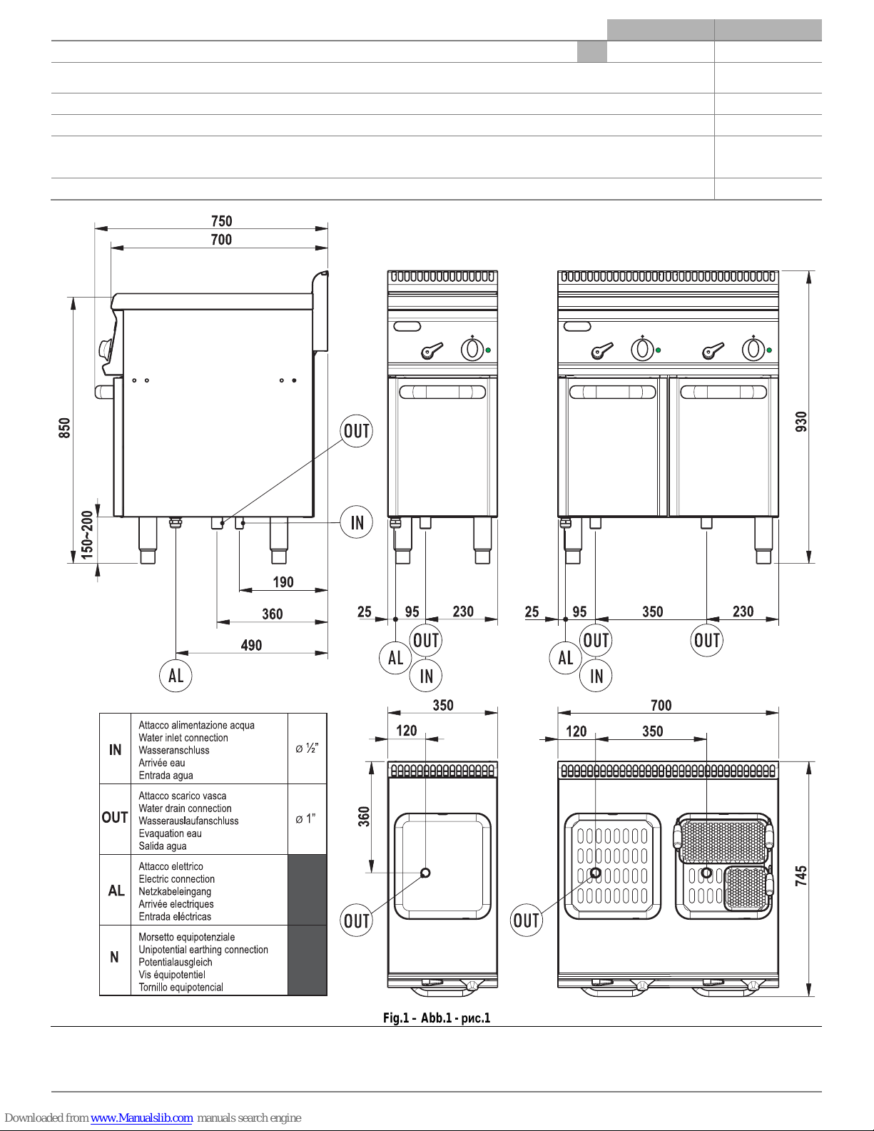
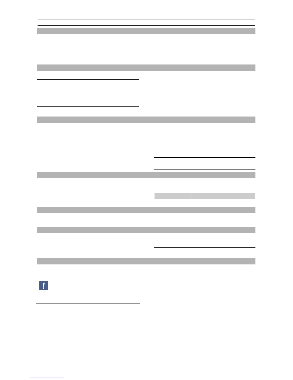
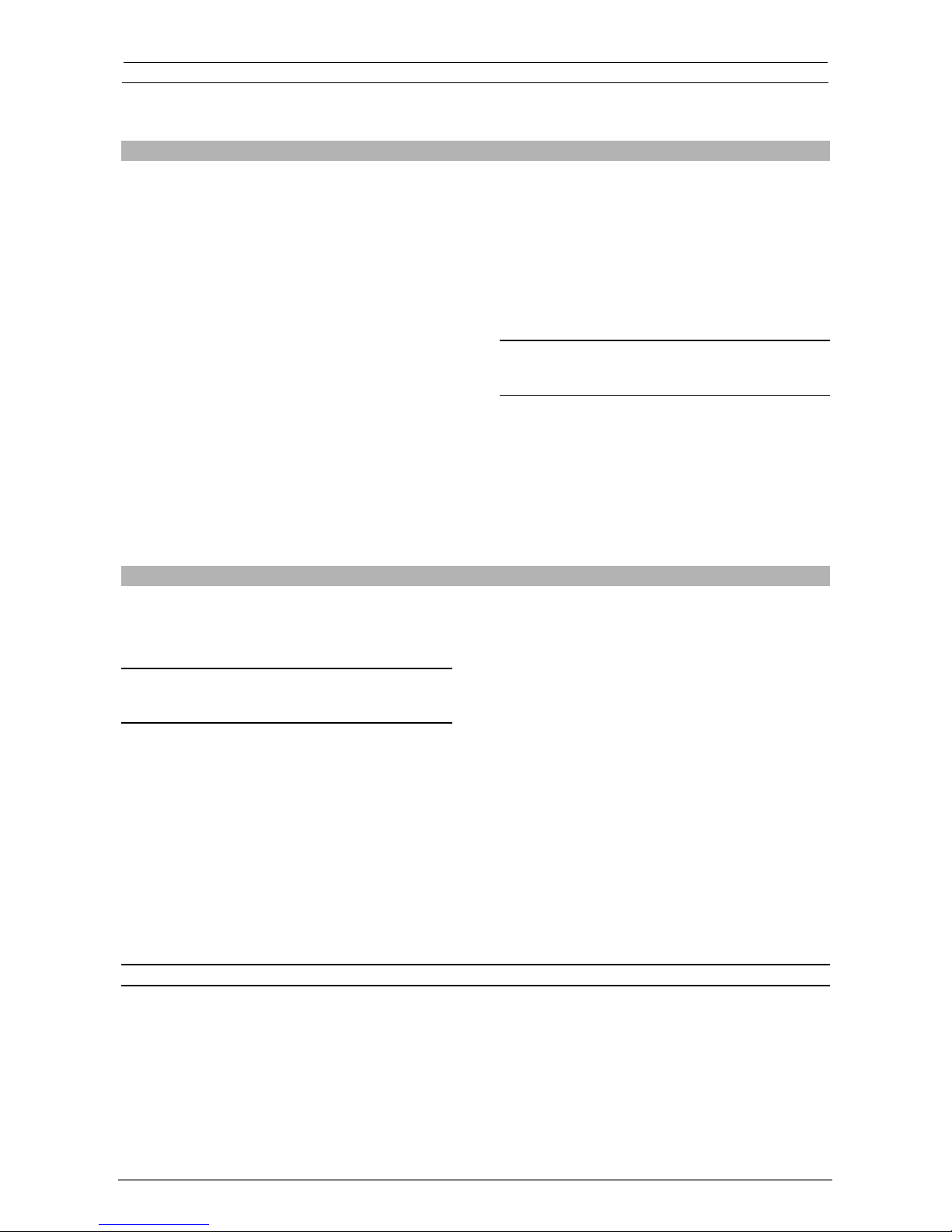
CP35E7 CP70E7
Dimensioni esterne, External dimensions, Außenmaße, Внешние размеры, Dimensions extérieures, Dimensiones externas. mm 350 × 750 × 850h 700 × 750 × 850h
Sez.minima cavo alim., Supply cable min.cross sec., Mindestquerschnitt Speisungkabel, Мин. Разрез электропровода, Sect. mini câble
alim., Sección mín. cable de alim.. 5×1.5mm25×1.5 mm2
Capacità vasca, Tub capacity, Beckeninhalt, Вместимость емкости, Capacité cuve, Capacidad recipiente. 23lt 23lt × 2
Potenza installata, Installed power, Nennleistung, Установленная мощность, Puissance installée, Potencia instalada. 4.8kW 4.8kW + 4.8kW
Tensione/Freq., Voltage/Freq., Spannung/Freq., Напряжение/Частота, Tension/Fréquence, Tensión/Frecuencia. 400V ~ 3N
50/60Hz 400V ~ 3N
50/60Hz
Dimensioni vasca, Tub dimensions, Beckenmaße, Размер емкости, Dimensions cuve, Dimensiones recipiente. GN2/3 2×GN2/3
aaaaaaaaaaaaaaaaaaaaaaaaaaaaaaa
aaaaaaaaaaaaaaaaaaaaaaaaaaaaaaa
aaaaaaaaaaaaaaaaaaaaaaaaaaaaaaa
aaaaaaaaaaaaaaaaaaaaaaaaaaaaaaa
aaaaaaaaaaaaaaaaaaaaaaaaaaaaaaa
aaaaaaaaaaaaaaaaaaaaaaaaaaaaaaa
aaaaaaaaaaaaaaaaaaaaaaaaaaaaaaa
aaaaaaaaaaaaaaaaaaaaaaaaaaaaaaa
aaaaaaaaaaaaaaaaaaaaaaaaaaaaaaa
aaaaaaaaaaaaaaaaaaaaaaaaaaaaaaa
aaaaaaaaaaaaaaaaaaaaaaaaaaaaaaa
aaaaaaaaaaaaaaaaaaaaaaaaaaaaaaa
aaaaaaaaaaaaaaaa
aaaaaaaaaaaaaaa
aaaaaaaaaaaaaaa
aaaaaaaaaaaaaaa
aaaaaaaaaaaaaaa
aaaaaaaaaaaaaaa
aaaaaaaaaaaaaaa
aaaaaaaaaaaaaaa
aaaaaaaaaaaaaaa
aaaaaaaaaaaaaaa
aaaaaaaaaaaaaaa
aaaaaaaaaaaaaaa
aaaaaaaaaaaaaaa
aaaaaaaa
Fig.1 – Abb.1 - рис.1

10/2007 IV 5410.255.00
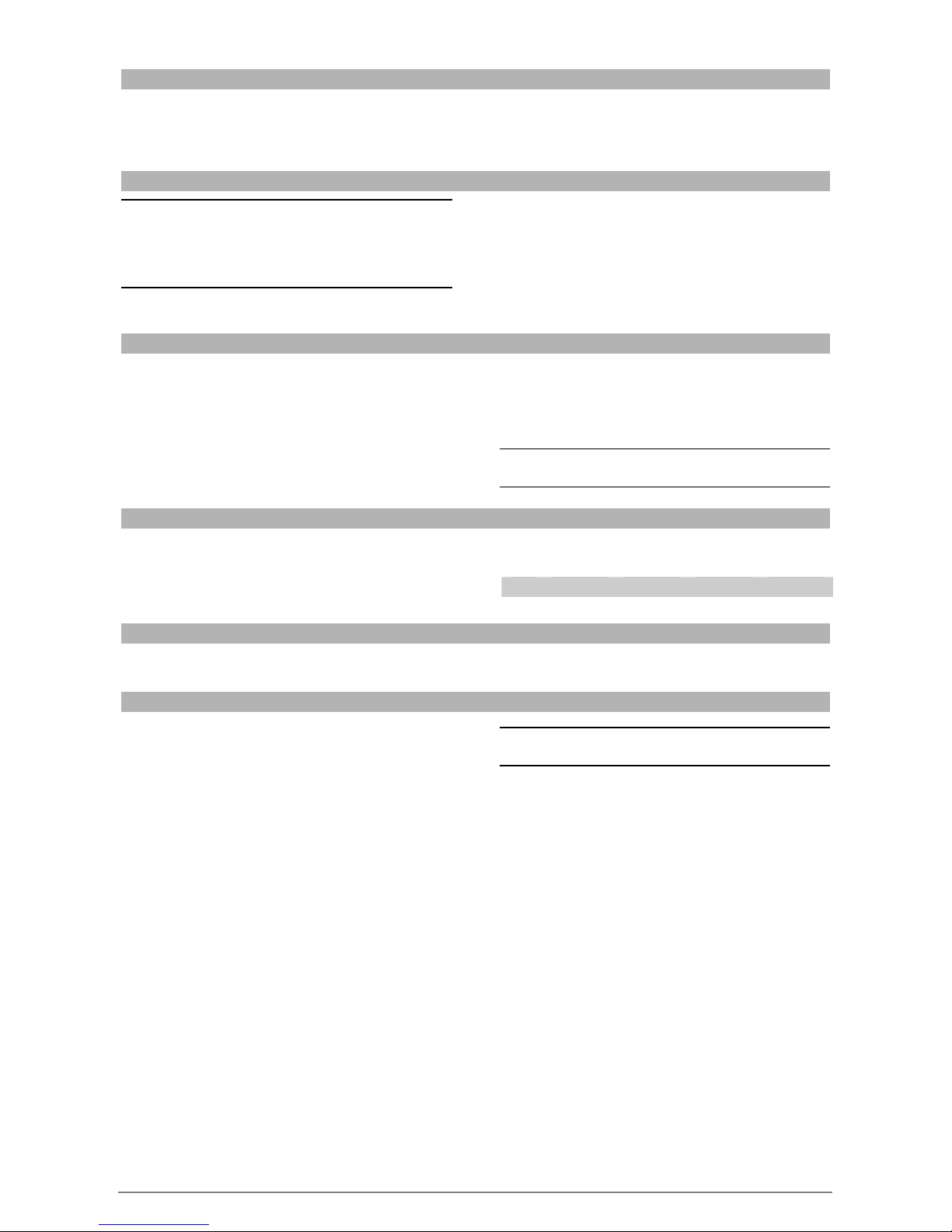
Fig.2 - Abb.2 - рис.2
Fig.3 – Abb.3 - рис.3 Fig.4 - Abb.4 - рис.4

IT - 1 5410.255.00
Parte 1 Installazione
CUOCIPASTA ELETTRICO
Avvertenze Generali
L’apparecchio, al quale si riferisce il presente libretto
d’istruzione, è costruito nel rispetto dei requisiti delle
Direttive: ”Bassa Tensione” 73/23/CEE, 93/68/CEE;
“Compatibilità elettromagnetica” 89/336/CEE, 92/31/CEE,
93/68/CEE.
L’installazione deve essere eseguita a cura di personale
qualificato secondo le norme e le prescrizioni vigenti nel
paese ed in conformità con le presenti istruzioni.
L’apparecchio deve essere utilizzato esclusivamente da
personale debitamente istruito ed usato solo per lo scopo per
cui è stato progettato.
Si consiglia, inoltre, un controllo annuale da eseguirsi a cura
di professionisti qualificati.
Togliere l’imballo dall’apparecchio, rimuovere la pellicola
protettiva e, se necessario, eliminare le tracce di colla con
l’ausilio di un solvente idoneo. Si raccomanda di smaltire
l’imballo secondo le prescrizioni vigenti.
I dati tecnici si rilevano dalla targhetta caratteristiche che è
applicata all’interno del cruscotto; quest’ultimo si smonta
togliendo le due viti poste sotto il cruscotto stesso.
Durante l’installazione sono da osservare e rispettare tutte le
norme vigenti quali:
Norme di Legge vigenti in materia;
Norme regionali e/o locali quali regolamento edilizio;
Prescrizioni e norme dell’azienda erogatrice dell’energia
elettrica;
Norme antinfortunistiche vigenti;
Prescrizioni antincendio;
Relative Norme CEI.
Si consiglia di installare l’apparecchio sotto ad una
cappa aspirante per l’evacuazione dei vapori prodotti
durante la cottura.
Qualora l’apparecchiatura dovesse essere sistemata vicino a
pareti, divisori, mobili da cucina, ecc., si raccomanda che
questi siano di materiale non combustibile; in caso contrario
dovranno essere rivestiti di materiale isolante termico non
combustibile.
Caratteristiche dell’apparecchio
Prima di procedere al collegamento rilevare i dati tecnici
necessari di all’installazione: tensione, frequenza, n° fasi e
potenza, sulla targhetta caratteristiche dell’apparecchiatura.
La targhetta matricola (in poliestere autoadesivo) si
trova dietro al pannello portacomandi “T” (fig.3).
L’installatore deve provvedere al collegamento previa
interposizione di un interruttore principale, facilmente
accessibile che deve interrompere l’erogazione d’energia in
modo onnipolare. I contatti in apertura devono avere tra loro
una distanza minima di almeno 3 mm per polo.
IL CAVO:
Non deve essere posizionato vicino a fonti di calore e
l’ambiente circostante non deve superare la temperatura
di 50°C
Deve essere protetto da un tubo metallico o di plastica
rigida.
Dovrà avere caratteristiche non inferiori a H07 RN-F.
Dovrà avere una sezione minima come specificato in
tabella (fig.1).
Per accedere alla morsettiera “M” (fig. 2) rimuovere il
cruscotto svitando le viti poste nella parte inferiore del
pannello stesso. Seguendo le indicazioni sullo schema
elettrico, collegare i conduttori del cavo d’alimentazione alla
morsettiera.
È indispensabile collegare l’apparecchiatura ad un’efficace
presa di terra e a tale scopo in prossimità della morsettiera
d’allacciamento, vi è una vite con il simbolo :al quale va
allacciato il conduttore di terra.
Prestare attenzione a far passare il cavo nel canale “B”
(fig.2) e bloccarlo con l’apposito pressacavo “AL” (fig.1).
L’apparecchiatura deve inoltre essere inclusa in un
sistema equipotenziale, tale collegamento viene effettuato
mediante una vite contrassegnata dal simbolo 9posta sul
fondo. Il filo equipotenziale deve avere una sezione di 10
mm2.
ATTENZIONE!
Nel modello CP35E7 è necessario fissare l’apparecchiatura a
pavimento tramite l’apposita staffa “F” (fig.2)

IT - 2 5410.255.00
Parte 2 Uso
Allacciamento alla rete idrica
L'apparecchiatura deve essere alimentata con acqua potabile
ad una pressione non inferiore a 1,5 bar. Collegare la
tubazione d’entrata dell'acqua anteponendo un rubinetto
d’intercettazione ed un filtro meccanico.
Scarico: l'acqua deve essere evacuata dal collettore di
scarico posto sotto il rubinetto “C” (fig.2).
Avvertenze Generali
Si raccomanda che tutti i lavori relativi all’allacciamento,
all’installazione ed alla manutenzione dell’apparecchio siano
eseguiti esclusivamente da personale qualificato ed in
osservanza di tutte le relative prescrizioni!
Questa apparecchiatura è concepita unicamente per la
cottura degli alimenti.
L’apparecchio è destinato solo ad uso collettivo e deve
essere asservito esclusivamente da personale
qualificato.
Prestare attenzione durante il funzionamento perché le
superfici di cottura sono molto calde.
Non utilizzare l’apparecchiatura con il livello dell’acqua
al di sotto della tacca di riferimento “L” (fig.2).
Messa in funzione
RIEMPIMENTO DELLA VASCA:
Controllare che il rubinetto di scarico dell'acqua posto
all'interno dell'apparecchio sia chiuso (leva orizzontale).
Introdurre l'acqua, fino al livello segnato sulla vasca.
Caricare l'acqua in vasca aprendo il rubinetto “W” (fig.1)
posto sul cruscotto frontale dell'apparecchio l'acqua uscirà
dall'erogatore posto in vasca.
Il livello dell'acqua é mantenuto dallo sfioratore; quest'ultimo
permette lo scarico delle schiume di cottura ed un ricambio
costante dell'acqua.
La quantità massima di cibo consentita é pari a 4 kg per
carico.
ATTENZIONE!
Non utilizzare mai l’apparecchio a secco.
Accensione
Attivare l’interruttore posto a monte dell’apparecchiatura.
Ruotare la manopola “A” (fig.2 - 4) facendo collimare l’indice
del cruscotto con la gradazione corrispondente alla
temperatura dell’acqua desiderata. L’accensione della
lampada spia verde indica la presenza di tensione “S” (fig.3).
Pos. 0 1 2 3
KW - 1.6 3.2 4.8
Spegnimento
Posizionare la manopola “A” (fig.2) sulla posizione di
spegnimento “0”. Disinserire l’interruttore elettrico posto a monte
dell’apparecchiatura.
Svuotamento della vasca
Dopo aver spento l’apparecchio, scaricare la vasca aprendo
il rubinetto “C” (fig.2). (leva in posizione verticale) ATTENZIONE!
Terminato lo svuotamento della vasca richiudere la valvola.
Pulizia
La pulizia deve essere effettuata solamente ad
apparecchio raffreddato.
Non lavare l’apparecchiatura con getti d’acqua,
poiché eventuali infiltrazioni ai componenti
elettrici potrebbero pregiudicare il regolare
funzionamento dell’apparecchiatura e dei
sistemi di sicurezza!
Si ricorda, che la pulizia è molto importante per il buon
funzionamento e per una lunga durata dell’apparecchio.
Le parti amovibili sono da lavare separatamente con acqua
calda e detergente e da sciacquare poi con acqua corrente.
Per la pulizia delle parti d’acciaio inossidabile non sono da
impiegare sostanze aggressive o comunque detergenti
abrasivi. L’uso di paglietta di ferro è sconsigliato, poiché può
provocare formazione di ruggine. Per lo stesso motivo evitare
il contatto con materiali ferrosi.
Durante la pulizia evitare anche l’utilizzo di carta o tela
vetrata; nel caso di sporco tenace si consiglia l’ausilio di
spugne (es. Scotch Brite). In caso di sporco tenace può
essere usato anche dello spray per forni e grill comunemente
reperibili. In questo caso osservare attentamente le
avvertenze del produttore.
Allo scopo di ridurre l'emissione in ambiente di sostanze
inquinanti, si consiglia di pulire l'apparecchiatura con prodotti
aventi una biodegradabilità superiore al 90%.
Qualora l’apparecchio resti inattivo per un periodo
prolungato, si consiglia, dopo aver eseguito la pulizia, di
stendere sulle superfici esterne un velo di protettivo
comunemente reperibile sul mercato.
IT - 3 5410.255.00
Termostato di sicurezza
L’apparecchiatura è dotata di un termostato di sicurezza che
interviene interrompendo l’alimentazione elettrica in caso di
funzionamento anomalo.
Per ripristinare il funzionamento dell’apparecchio premere il
pulsante “E” (fig.3). Quest’operazione deve essere eseguita
da un tecnico specializzato.
Sostituzione di parti
La sostituzione di parti difettose, deve essere eseguita
esclusivamente da personale abilitato. Prima di iniziare
qualsivoglia lavoro scollegare l’apparecchio dalla rete di
distribuzione elettrica. Dopo aver tolto il pannello
portacomandi tutte le parti funzionali dell'apparecchio
diventano facilmente accessibili.
I pezzi di ricambio sono da richiedere esclusivamente al costruttore o ad un rivenditore autorizzato.
Manutenzione
L'apparecchiatura non necessita di particolare manutenzione oltre alla normale pulizia; si consiglia comunque un controllo
annuale dal centro d’assistenza e a tale scopo si raccomanda la stipula di un contratto di manutenzione.
Avvertenze per la sicurezza
SI RICORDA CHE L’APPARECCHIO:
Deve essere utilizzato solamente sotto sorveglianza!
Durante l’uso, le superfici diventano molto calde e
pertanto si raccomanda particolare prudenza!
Tutte le parti dell’apparecchiatura, che durante l'uso
vanno in contatto con il cibo, sono da pulire
regolarmente seguendo il capitolo "Pulizia e cura"
Ecologia e ambiente
Le nostre apparecchiature sono studiate ed ottimizzate, con
test di laboratorio, al fine di ottenere prestazioni e rendimenti
elevati. Comunque, al fine di contenere i consumi energetici
(elettricità, gas ed acqua), si consiglia di evitare l’utilizzo
dell’apparecchiatura per lungo tempo a vuoto o in condizioni
che compromettano il rendimento ottimale.
Tutti i materiali utilizzati per l’imballo sono compatibili con
l’ambiente. Essi possono essere conservati senza pericolo o
essere bruciati in un apposito impianto di combustione dei
rifiuti. I componenti in materiale plastico soggetti a eventuale
smaltimento con riciclaggio sono:
Polietilene: pellicola esterna dell’imballo e/o pellicola
pluribol.
Polipropilene: reggette
Polistirolo espanso: angolari, lastre e cubi di protezione
Alla fine del ciclo di vita del prodotto, evitare che
l’apparecchiatura venga dispersa nell’ambiente.
Le nostre apparecchiature sono realizzate con materiali
metallici (acciaio inox, ferro, lamiera alluminata, ecc.) in
percentuale superiore al 90% ed è quindi possibile un
riciclaggio degli stessi, per mezzo delle strutture tradizionali
di recupero, nel rispetto delle normative vigenti nel proprio
paese.
Rendere inutilizzabile l’apparecchiatura per lo smaltimento
rimuovendo il cavo d’alimentazione e qualsiasi eventuale
dispositivo di chiusura vani o cavità per evitare che qualcuno
possa rimanere chiuso al loro interno.
Il costruttore declina ogni responsabilità nel caso di danni provocatida errata installazione, impropria manutenzione ed
inosservanza delle prescrizioni di sicurezza!

GB / IE - 1 5410.255.00
Part 1 Installation
ELECTRIC PASTA COOKER
General Instructions
The appliance referred to in this manual has been
manufactured in conformity to the following Directives:
73/23/EEC, 93/68/EEC “Low Voltage”; 89/336/EEC,
92/31/EEC, 93/68/EEC “Electromagnetic Compatibility".
The appliance shall be installed by a qualified Technician
according to the regulations and directives in force in the
country where it is installed, as well as the instructions in this
manual.
The appliance shall be used exclusively by trained personnel
and only for the purpose for which it has been designed.
The appliance should be checked once a year by a qualified
technician.
Remove the packaging form the appliance as well as the
protective plastic sheet, and, if necessary, remove traces of
glue with a suitable solvent.
To dispose of the packaging, follow local directives.
The technical specifications of the appliance can be found on
the data plate located inside the control panel, which can be
removed by loosening the two screws below the panel.
When installing the appliance, all the regulations in force
shall be observed, such as:
All applicable national laws in effect;
All regional or local regulations, such as building codes;
Directives and regulations of the local electrical energy
supplier;
Accident prevention regulations in effect;
Fire prevention regulations;
Applicable I.E.C. regulations.
WARNING!
The appliance should be installed under an extractor fan
for the removal of cookingfumes.
If the appliance is installed near walls, panels or kitchen
furniture, etc., they must be made of fire-proof material; if
they are not, they must be protected with fire-proof material
which insulates from heat.
Connection to the mains
Before connecting the appliance to the mains, compare the
electrical set-up data on the data plate to the characteristics
of the local electrical energy supply.
The self-adhesive polyester data plate is behind the
control panel “T” (fig.3) inside the appliance.
Adjust the height of the appliance by regulating the feet, and
make sure that it is perfectly level.
The appliance is equipped with a connecting cable to which
the installer must connect a circuit breaker which cuts off the
flow of electricity in all poles; the distance between the open
contacts must be at least 3 mm.
The circuit breaker must be easy to reach.
The cable must not be placed near heat sources.
The area around the cable must not have a temperature
above 50° C.
If the cable must ever be replaced, consult the wiring
diagram attached.
The electric supply cable must not have specifications
inferior to type H07 RN-F. It must have a cross-sectional
area of at least 1.5 mm2× 5 tab. (fig.1).
To reach terminal board “M” (fig.2), remove the control panel
by loosening the screws on the lower part of the panel.
Disconnect the conductors of the electric supply cable from
the terminal board, loosen the cable clamp, and replace the
cable following the procedure inversely.
It is absolutely necessary to earth the appliance.
For this purpose, there is a screw marked with the symbol :
near the terminal board to which the earthing conductor must
be connected.
Make sure you slide the cable in the canalization “B” (fig.2),
hold the cable in place until you can block it with cable clamp
“AL” (fig.1).
The appliance must also be connected to a unipotential
earthing circuit. This connection can be made using the
screw marked with the symbol 9placed under the
appliance.
The equipotential wire must have a section of 10 mm2.
WARNING!
The CP35E7 model must be fixed to the floor with the
relevant bracket “F” (fig.2).
GB / IE - 2 5410.255.00
Part 2 Use
Plumbing
The appliance must be plumbed to the drinking water mains
at a minimum pressure of 1.5 bar. Connect the water pipe
after having installed an on-off cock and mechanical filter.
Drain: the water must be drained by the manifold under the
cock “C” (fig.2).
General instructions
Connections to the mains, installation, and maintenance
of the appliance shall be carried out by qualified
technicians only, in observance of all applicable
regulations!
This appliance has been designed exclusively for
cooking foods.
The appliance has been designed for use in community
kitchens and must be operated
exclusively by qualified personnel.
Care must be taken when operating the machine as
surfaces are very hot.
Do not put the machine into operation if the water in the
basin goes below the water level marked “L” (fig.2).
Starting up
FILLING THE TUB:
Check that the water outflow tap placed on the front part of
the appliance is in the closed position.
Fill the tub with water up to the level marked on the tub.
Fill the tank with water by opening cock “W” (fig.1), on the
appliance’s front panel. The water will come out of the
distributor in the tank.
The level of the water is maintained by the overflow which
drains off the froth that forms during cooking and keeps water
changed constantly.
The maximum quantity of food allowed is 4 kg each load.
WARNING!
Do not use the appliance without water.
Turning the appliance on
Press the circuit breaker switch to connect the appliance to
the mains.
Rotate knob “A” (fig.2 - 4) so that the indicator mark on the
control panel corresponds to the water temperature desired.
When the green indicator light is on, the appliance is supplied
with electric power “S” (fig.3).
Pos. 0 1 2 3
KW - 1.6 3.2 4.8
Turning the appliance off
Place the knob “A” (fig.2) in the off position “0”. Press the circuit breaker switch to disconnect the appliance
from the mains.
Emptying the tub
After the appliance have been turned off, drain the tank by
opening the cock (lever in the upright position), item “C”,
(fig.2).
WARNING!
When the tub is empty always close the tap.
GB / IE - 3 5410.255.00
Cleaning and care of the appliance
The unit must be cold to clean it.
Do not wash the appliance with water jets, as
water might reach the electric components,
resulting in faulty operation and damage to
safety systems!
Keeping the appliance clean is very important for a long and
trouble-free working life.
The removable parts should be washed separately with warm
water and detergent, then rinsed in running water.
Do not use harsh or abrasive detergents to clean the
stainless steel parts. Iron cleaning pads should not be used
as they cause the formation of rust. For the same reason,
avoid contact with ferrous materials.
When cleaning, avoid using abrasive paper or cloth; we
recommend using sponges (ex. Scotch Brite) to remove
stubborn deposits. You can also use common sprays for
cleaning ovens and grills to remove stubborn deposits. If
spray products are used, follow the manufacturer’s
instructions.
To minimise the emission of polluting substances in the
environment we suggest cleaning the appliance with
products that are at least 90% biodegradable.
If the appliance will not be used for a long period of time, it
should be thoroughly be cleaned, and covered with a
protective sheet of plastic of the type commonly found in
shop.
Safety Thermostat
The appliance is equipped with a safety thermostat which
cuts off the electric power supply in case of irregular
operation.
To turn the appliance on again, press button “E” (fig.3).
This must be done by a specialised technician.
Replacing parts
Only qualified personnel should replace faulty parts. Prior to
commencing any kind of work, disconnect the unit from the
gas distribution network.
After having removed the control panel, all the functional
parts of the appliance are easily accessible
Only order spare parts from the manufacturer or an authorised reseller.
Maintenance
The appliance needs no specific maintenance besides normal cleaning; we do however suggest having it checked once a
year by the assistance centre for which, we recommend drawing up a maintenance contract.
Safety precautions
REMEMBER THAT THE APPLIANCE:
Must never be left unattended when it is being used!
When the unit is switched on, its surfaces get very hot
so please take great care!
The appliance is intended for professional use and
therefore only qualified personnel should use it!
Installation as well as any conversion or adaptation to a
different type of gas must be carried out in accordance
with current laws and only by qualified and authorized
personnel.
At least once a year have the appliance checked by
qualified personnel.
All the parts that come into contact with oil or fat during
use, should be cleaned regularly as indicated in the
chapter “Cleaning and Care”.
Ecology and the Environment
Our appliances are studied and optimised, with lab tests, to
provide high performance and yields. However, to keep
energy consumption low (electricity, gas and water), we
suggest not using the appliance for any length of time if it is
empty or in conditions that compromise optimum yield.
All packaging materials are environment-friendly. They can
be kept without problem or burnt in a waste incinerator plant.
The plastic components that can be recycled are:
Polyethylene: external packaging material and/or pluribol
film
Polypropylene: straps
Polystyrene foam: corner pieces, sheets and protection
blocks
At the end of the appliance’s useful life, dispose of it properly.
90% of each appliance is made of metal (stainless steel, iron,
aluminated sheet, etc.) hence it can be recycled by the
relative recycling organisations in compliance with the
standards in force in your country.
Prepare the appliance for disposal, so it cannot be used any
more, by removing the power cable and any locks so that no
one can get locked inside accidentally.
The Manufacturer declines any responsibility for damage caused by improper or incorrect installation or maintenanceof
the appliance, or failure to observe safety regulations!

DE - AT - CH - 1 5410.255.00
Teil 1 Installation
ELEKTRISCHER NUDELKOCHER
Allgemeine Anmerkungen
Die in dieser Gebrauchsanweisung beschriebenen Geräte
wurden nach den Vorschriften: “Niederspannung”
73/23/CEE, 93/68/CEE; “Elektromagnetische Kompatibilität”
89/336/CEE, 92/31/CEE, 93/68/CEE Konstruiert.
Die Installation muss von kompetentem Personal laut der
Vorschriften und Gesetze des Landes sowie in
Übereinstimmung mit dieser Gebrauchsanweisung
durchgeführt werden.
Das Gerät darf ausschließlich von gebührend geschultem
Personal und für den vorgesehenen Zweck verwendet
werden. Außerdem wird empfohlen, einmal jährlich eine
Kontrolle von qualifiziertem Personal durchführen zu lassen.
Die technischen Daten entnimmt man dem Typenschild, das
sich am Hauptgehäuse des Gerätes befindet. Die
Verpackung des Gerätes entfernen, die Schutzfolie
abnehmen und eventuelle Klebstoff-Rückstände mit einem
geeignetem Lösungsmittel entfernen.
Das Verpackungsmaterial muss vorschriftsmäßig entsorgt
werden.
Die technischen Daten sind am Typenschild angeführt, das
sich auf der Innenseite der Bedienungsblende befindet; die
Bedienungsblende kann mittels Ausschrauben der unter der
Blende befindlichen Schrauben abgenommen werden.
Während der Installation sind alle geltenden Vorschriften zu
berücksichtigen:
Vorschrift der gültigen Gesetze der Materie.
Regionale und/oder lokale Bauvorschriften.
Vorschriften und Regel des Stromwerkes.
Geltende Unfallverhütungsgesetze.
Vorschriften der Brandverhütung.
Entsprechende Vorschriften CEI.
Es wird empfohlen, das Gerät unter einer Abzughaube
aufzustellen, um die während des Garens erzeugten
Dämpfe abzuleiten.
Sollte das Gerät in der Nähe von Wänden, Trennwänden,
Küchenmöbeln u.s.w. installiert werden, ist darauf zu achten,
dass diese hitzebeständig sind; anderenfalls sind diese mit
hitzebeständigem Isoliermaterial zu verkleiden.
Netzanschluss
Vor dem Anschluss sind folgende für die Geräteversorgung
notwendigen Daten am Typenschild zu prüfen: Spannung,
Frequenz, Phasenanzahl und Leistung.
Das Typenschild (aus selbsthaftendem Polyester)
befindet sich hinter der Bedienblende „T“ (Abb.3).
Der Installateur muss beim Anschluss einen leicht
zugänglichen Hauptschalter zwischenschalten, der die
Stromzufuhr allpolig unterbricht.
Die mindeste Kontaktöffnungsweite muss pro Pol 3 mm
betragen.
DAS KABEL:
Darf nicht in der Nähe von Hitzequellen verlegt werden
und die Raumtemperatur darf nicht über 50°C liegen.
Es muss in einem Metallrohr oder in einem steifen
Kunststoffrohr verlegt werden.
Es muss mindestens dem Typ H07 RN-F entsprechen.
Es muss einen Mindestquerschnitt gemäß der Tabelle
aufweisen (Abb.1).
Um an das Klemmenbrett “M” (Abb. 2) zu gelangen, ist die
Bedienblende durch Ausschrauben der am unteren Teil der
Blende selbst befindlichen Befestigungsschrauben zu
entfernen. Unter Befolgung der Anweisungen des
elektrischen Schaltplans die Leiter des Netzkabels an der
Klemmleiste anschließen.
Das Gerät muss unbedingt geerdet werden. Zu diesem
Zweck befindet sich in der Nähe des
Anschlussklemmenbretts eine durch das Symbol
:gekennzeichnete Erdungsklemme, an der das
Erdungskabel befestigt wird.
Das Kabel muss immer durch den Mehrlochkanal „B“ (Abb.2)
entlang geführt und mit der Kabelklemme “AL” (Abb.1) fixiert
werden.
Das Gerät ist ferner in ein Potentialausgleichssystem
einzubeziehen. Der Anschluss erfolgt über die mit dem
Symbol 9gekennzeichnete Schraube, die sich an der
Geräterückwand befindet.
Der Potentialleiter muss einen Mindestquerschnitt von
10mm2aufweisen.
ACHTUNG!
Das Modell CP35E7 muss mit dem dazu vorgesehenen
Bügel „F“(Abb.2) am Fußboden befestigt werden.
DE - AT - CH - 2 5410.255.00
Teil 2 Gebrauch
Wasseranschluss
Der Nudelkocher muss mit Trinkwasser gespeist werden,
dessen Druck nicht unter 1,5 mbar sein muss.
Die Wasseranchlussleitung anschließen; um den Zufluss zu
Kontrollieren, bauen einen Wasserhahn und einen Siebfilter
ein.
Abfluss: das Wasser muss über die Abfluss-Sammelleitung
unter dem Hahn “C” (Abb.2) abfließen.
Allgemeine Anmerkungen
Alle Maßnahmen bezüglich elektrischem Anschluss,
Installation sowie Wartung des Gerätes dürfen nur von
qualifiziertem Personal unter Beachtung aller
entsprechenden
Vorschriften durchgeführt werden!
Dieses Gerät ist ausschließlich für das Kochen von
Speisen gedacht.
Das Gerät ist ein Großküchengerät und darf nur von
qualifiziertem Personal betrieben werden.
Es ist darauf zu achten, dass sich die
Geräteoberflächen während des Betriebs erhitzen.
Das Gerät darf nicht betrieben werden, falls das
Wasser im Becken unter der Markierung „L“ (Abb. 2) ist.
Inbetriebnahme
ANFÜLLEN DES BECKENS:
Überprüfen, dass der Wasserabflusshahn, der sich der
Gerätevorderseite befindet, geschlossen Ist Hebel in
waagerechter Position).
Bis zur Markierung am Becken Wasser einfüllen.
Den Wasserhahn "W", (Abb.1), der sich auf der
Gerätevornseite befindet, aufdrehen, und das Becken
Wasser auffüllen.
Das Wasser fließt aus der sich in dem Becken befindeten
Öffnung hinaus. Der Wasserspiegel wird dank dem Überlauf
konstant gehalten, der dazu den Ablauf des Siedewassers
und die ständige Wasserzirkulation gewährleistet.
Das Gargut darf ein Gewicht von 4 kg. Nicht überschreiten.
ACHTUNG!
Das Gerät nie trocken betreiben.
Inbetriebnahme
Den Hauptschalter bauseits des Gerätes einschalten.
Den Drehschalter “A” (Abb.2 - 4) drehen, bis die gewünschte
Wassertemperatur mit der Markierung an der
Bedienungsblende übereinstimmt.
Die grüne Kontrolllampe leuchtet auf, um zu zeigen, dass
das Gerät unter Spannung ist “S” (Abb.3).
Pos. 0 1 2 3
KW - 1.6 3.2 4.8
Außerbetriebnahme
Den Drehschalter “A” (Abb.2) auf Position “0” drehen. Den Hauptschalter bauseits des Gerätes ausschalten.
Entleeren des Beckens
Nachdem das Gerät ausgeschalte wurde muss der
Wasserhahn zur Entleerung des Beckens aufgedreht
werden. (Hebel in senkrechter Position, siehe Teil “C”,
(Abb.2).
ACHTUNG!
Nach dem Entleeren das Ventil wieder schließen.
Reinigung und Instandhaltung
Die Reinigung ist nur bei abgekühltem Gerät
vorzunehmen.
Zur Reinigung des Gerätes keinen Wasserstrahl
verwenden, da das Eindringen von Wasser in die
elektrischen Teile den einwandfreien Betrieb des
Gerätes und der Sicherheitsvorrichtungen
beeinträchtigen könnte.
Die Reinigung ist für einen einwandfreien Betrieb und eine
lange Lebensdauer des Geräts sehr wichtig.
Die abnehmbaren Teile separat mit warmem Wasser und
Reinigungsmittel waschen und unter fließendem Wasser
nachspülen.
Zur Reinigung der Teile aus rostfreiem Stahl, keine aggressive
Mittel oder scheuernde Reinigungsmittel verwenden. Die
Benutzung von Stahlwolle auf Edelstahlteilen ist zu vermeiden,
da sich hierdurch Rost bilden könnte. Aus demselben Grund ist
derKontaktmiteisenhältigemMaterialzumeiden.
Glaspapier oder Schmirgelpapier sollten bei der Reinigung
nicht verwendet werden; bei stärkerer Verschmutzung
empfehlen wir die Benutzung von Schwämmen (z.B.
Schwamm der Fa. Scotch Brite). Bei hartnäckigen
Verschmutzungen kann handelsüblicher Backofen- oder
Grillreiniger zur Hilfe genommen werden. Dazu sind die
Hinweise des jeweiligen Herstellers zu beachten.
Umdie Umweltbelastungdurch Reinigungsmittelzuverringern,
istesempfehlenswert,dasGerätnur mitProdukten,die zu
mindestens90%biologischabbaubarsind, zureinigen.
Sollte das Gerät für längere Zeit nicht verwendet werden, ist
es ratsam, die Stromversorgung zu unterbrechen, das Gerät
mit Seifenwasser zu reinigen, gut nachspülen und das Gerät
sorgfältig trockenzureiben. Anschließend eine dünne Schicht
Vaselinöl auftragen.
DE - AT - CH - 3 5410.255.00
Sicherheitsthermostat
Das Gerät ist mit einem Sicherheitsthermostat ausgestattet,
der bei abnormalem Betrieb durch Unterbrechung der
elektrischen Speisung einschreitet.
Um das Gerät wieder in Betrieb zu nehmen, ist der
Druckknopf “E” (Abb.3) zu betätigen. Diese Durchführung
muss von einem spezialisierten Techniker vorgenommen
werden.
Austausch von Teilen
Der Austausch von defekten Teilen hat nur durch
Fachpersonal zu erfolgen. Bevor jegliche Arbeit angefangen
wird, ist grundsätzlich der Gasabsperrhahn zu schließen.
Nach Abnahme der Bedienblende sind alle Funktionsteile
des Gerätes leicht zugänglich.
Die Ersatzteile ausschließlich beim Herstelleroder befugten Händler bestellen.
Wartung
Das Gerät benötigt neben der normalen, regelmäßigen Reinigung keine besonderen Wartungsarbeiten; es wird dennoch eine
jährliche Kontrolle durch eine Kundendienststelle empfohlen, weshalb der Abschluss eines Wartungsvertrages ratsam ist.
Sicherheitshinweise
FOLGENDES BEACHTEN:
Das Gerät nur unter Aufsicht betreiben!
Während des Betriebs werden die Geräteoberflächen
heiß - besonders Acht geben!
Das Gerät ist für gewerbliche Zwecke geplant und darf
nur durch Fachpersonal bedient werden!
Die Geräteinstallation sowie eine eventuelle Umstellung
oder Anpassung auf eine andere Gasart, darf nur
gemäß den einschlägigen gesetzlichen Vorschriften und
durch qualifiziertes Fachpersonal, durchgeführt werden.
Das Gerät mindestens einmal jährlich von Fachpersonal
kontrollieren lassen.
Alle Geräteteile, die während des Gebrauchs mit den
Speisen in Verbindung treten, sind gemäß Kapitel
“Reinigung und Wartung” regelmäßig zu reinigen.
Umweltschutz
Unsere Geräte werden durch zahlreiche
Laboruntersuchungen geprüft und optimiert, um so
besonders hohe Leistungen zu erzielen. Dennoch wird zur
Einschränkung des Energieverbrauchs (Strom, Gas und
Wasser) empfohlen, das Gerät nicht für längere Zeit
unbenutzt eingeschaltet zu lassen und es nur unter
optimalen Betriebsbedingungen zu verwenden.
Alle für die Verpackung verwendeten Materialien sind
umweltverträglich. Sie können daher ohne Gefahr aufbewahrt
oder in einer dafür vorgesehenen Müllverbrennungsanlage
verbrannt werden. Die folgenden Kunststoffteile sind für eine
eventuelle Wiederverwertung geeignet:
Polyäthylen: Außenhülle der Verpackung und/oder
Noppenfolie
Polypropylen: Bänder
Polystyrolschaum: winkel- oder würfelförmiges
Schutzmaterial sowie Schutzabdeckungen
Nach Ablauf der vorgesehenen Lebensdauer des Gerätes ist
dieses ordnungsgemäß zu entsorgen.
Alle unsere Geräte werden zu mehr als 90% aus Metall
hergestellt (Edelstahl, Eisen, Aluminiumblech etc.), sie
können daher den jeweiligen ortsüblichen Entsorgungsstellen
problemlos zur Wiederverwertung zugeführt werden.
Vor der Entsorgung sind die Geräte funktionsuntüchtig zu
machen, indem das Netzkabel am Gerät abgeschnitten wird.
Eventuell vorhandene Verschlussvorrichtungen an
Geräteinnenräumen oder an der Oberseite des Gerätes
entfernen, damit sich niemand darin einschließen kann.
Der Hersteller übernimmt für Schäden aufgrund falscher Installation, unsachgemäßer Wartung und Nichtbeachtung der
Sicherheitsvorschriften keine Haftung.
py - 1 5410.255.00
Часть 1 Установка
ЭЛЕКТРИЧЕСКАЯ МАКАРОНОВАРКА
Общие предупреждения
Оборудование, описанное внастоящей инструкции
изготовлено всоответствии снормативами: «Низкого
Напряжения 73/23/CEE, 93/68/CEE; “Электромагнитного
соответствия” 89/336/CEE, 92/31/CEE, 93/68/CEE.
Установка должна осуществляться квалифицированным
персоналом, согласнот нормам ипредписаниям,
действующим вданной стране ивсоответствии с
настоящими инструкциями.
Оборудование должно быть использовано только
квалифицированным персоналом итолько для целей,
для которых оно было спроектировано.
Рекомендуется также производить ежегодный контроль с
помощью квалифицированных специалистов.
Снять упаковку оборудования, убрать защитную пленку,
если необходимо удалисть остатки клея спомощью
специального растворителя.
Рекомендуется перерабатывать упаковку согласно
действующим предписаниям.
Технические данные указаны на табличке характеристик,
которая находиться свнутренней стороны панели
управления, которую возможно снять, развинчивая два
винта, находящиеся внижней части панели.
Во время установки соблюдать все действующие нормы:
Действующие соответствующие нормы;
Региональные и/или местные нормы сторительного
регулирования;
Предписания инормы учреждения, распределяющего
электроэнергию;
Действующие нормы по предотвращению несчастных
случаев;
Противопожарные предписания;
Соответствующие нормы CEI.
Рекомендуется устанавливать оборудование под
вытяжной трубой для эвакуации паров,
производимых во время готовки.
Если оборудование должно быть установлено вблизи
стен, разделительных перегородок, кухонной мебели и
т.д., рекомендуется, чтобы перечисленные предметы
были из невозгораемого материала; впротивном случае
они должны быть облицованы термоизоляционным
невозгораемым материалом.
Характеристики оборудования
Перед началом установки определить технические
данные: напряжение, частота, количество фаз и
мощность на табличке характеристик, необходимые для
питания оборудования.
Идентификационная табличка (из самоклеющегося
полиестра) находиться за панелью управления.“T”
(рис.3).
Инсталлятор должен обеспечить подсоединение
через промежуточное положение главного
переключателя, который должен прерывать подачу
энергии многополюсным спрособом. Открытые контакты
должны иметь минимум 3mm.
ПРОВОД:
Не должен находиться около источника жара;
температура окружающего помещения около
провода не должна превышать 50°C.
Провод должен быть защищен металлической
трубой или жестким пластиком.
Провод питания должен иметь характеристики
не ниже H07 RN-F
Должен иметь минимальный разрез, указанный
втаблице (рис.1).
Для открытия клеммной коробки “M” (рис.2) снять
передний щиток, развинчивая винты, расположенные в
нижней части самой панели.
Следуя указаниям электрической схеме, подсоединить
проводники провода питания кклеммной коробке.
Необходимо подсоединить оборудование к
действующему заземлителю. Для этого на конце
подсоединительной клеммной коробки находиться винт
со значком :ккоторомуподсоединяется заземляющий
провод.
Необходимо провести провод через канал “B” (рис.2) и
заблокировать его специальным прессом “AL” (рис.1).
Кроме этого оборудование должно быть включено в
эквипотенциальную систему, подобное подсоединение
производиться посредством винта обозначенного 9,
находящегося взадней части оборудования.
Эквипотенциальный провод должен иметь разрез 10mm2.
Вмодели CP35E7 необходимо прикрепить оборудование кполу посредством специального крепления “F” (рис.2)

py - 2 5410.255.00
Часть 2 Использование
Подсоединение кгидросети
Оборудование должно иметь выход кпитьевой воде,
давление которой не ниже 1,5 бар. Подсоединить
трубопровод входа воды, устанавливая кран
переключения имеханический фильтр.
Слив: вода должна быть эвакуирована из сборника,
находящегося под краном “C” (рис.2).
Общие Предупреждения
Рекомендуется проводить всю работу,
относящуюся кподсоединению, инсталляции и
обслуживанию оборудования только
квалифицированному персоналу при условии
соблюдения всех предписаний!
Это оборудование было создано только для готовки
пищевых продуктов.
Оборудование предназначено для коллективного
пользования идолжно быть использовано только
квалифи цированным персоналом.
Быть внимательным во время готовки, потому что
все поверхности могут быть очень горячими.
Не использовать оборудование при уровне воды
ниже отметки “L” (рис.2).
Запуск вработу
ЗАПОЛНЕНИЕ ЕМКОСТИ:
Проконтролировать закрытие крана слива воды,
находящегося внутри оборудования ( горизонтальное
положение ручки)
Ввести воду до уровня обозначенного на емкости.
Залить воду вемкость открывая кран “W” (рис.1)
находящийся на передней панели управления, вода
выйдет из распределителя находящегося вемкости.
Уровень воды удерживается водосливом, который
обеспечивает слив пены готовки ипостоянную смену
воды.
Максимальное количество пищи равно 4 кг. на каждую
загрузку.
ВНИМАНИЕ!
Никогда не использовать оборудование всухую.
Включение
Активировать выключатель, расположенный вверхней
части оборудования.
Повернуть ручку “A” (рис.2 - 4) доводя показатель до
градации, соответствующей необходимой температуре
воды. Включение зеленой лампочки указывает на
наличие напряжения “S” (рис.3).
Поз. 0 1 2 3
KW - 1.6 3.2 4.8
Выключение
Позиционировать ручку “A” (рис.2) на позицию
выключения “0”. Выключить электровыключатель, находящийся вверхней
части оборудования.
Слив емкости
После выключения оборудования, слить емкость открыая
кран “C” (рис.2). (ручка ввертикальной позиции) ВНИМАНИЕ!
После слива воды закрыть клапан.
Чистка
Чистка должна производиться только при
охлажденном оборудовании.
Не чистить оборудование под сильным
напором воды, потому что возможно
проникновение воды вл внутренние
компоненты, что може повлечь за собой
нерегулярную работу оборудования и
системы безопасности!
Необходимо помнить, что чистка оборудования очень
важна для его хорошей работы идлительного
использования.
Вынимающиеся части должны чиститься отдельно
горячей водой ичистящим средством ипосле должны
ополоскиваться протечной водой.
Для чистки частей из нержавеющей стали нельзя
использовать агрессивные средства или обычные
абразивные порошки. Использование проволочной губки
не рекомендуется поскольку может спровоцировать
появление ржавчины. По этой же причине избегать при
чистке использования железных материалов, тяжелых
или грубых тряпок, атакже стальной шерсти Во время
чистки избегать также использование бумаги или губок из
стекловаты; на замену итолько вособых случаях можно
использовать распыленную пемзу. Вслучае сильного
загрязнения использовать губки ( например Scotch).
Также вслучае сильного загрязнения можно
использовать спрай для печей игрилей, продающейся в
свободной торговле. Вэтом случае проконсультировать
аннотацию производителя Во избежание выброса в
атмосферу загрязняющих элементов рекомендуется
использовать при чистке обрудования средства,
способность кбиологическому разрушению который
превышает 90%.
Если оборудование остается неактивным втечении
длительного времени, рекомендуется после
проведения чистки покрыть все поверхности
защитной пленкой, встречающейся всвободной
продаже.

py - 3 5410.255.00
Термостать безопасности
Оборудование имеет термостат безопасности который
прерывает подачу тока вслучае аномальной работы. Для перезапуска работы оборудования нажать кнопку “E”
(рис.3). Эта операция должна производиться
специализированным техником.
Замена частей
Замена неисправных частей должна производиться
только квалифицированным персоналом. Прежде чем
начинать работы по обслуживанию необходимо
отсоединить оборудование от сети. После съемки панели
управления все рабочие компоненты оборудования
становяться легкодоступными.
Запчасти для оборудования запрашиваются только упроизводителя или официального дистрибьютора.
Обслуживание
Оборудование не нуждается вспециальном обслуживании кроме обычной чистки; рекомендуется проводить
годовой контроль вцентре обслуживания идля этого рекомендуется заключение контракта по обслуживанию.
Предупреждения по безопасности
НЕБХОДИМО ПОМНИТЬ, ЧТО ОБОРУДОВАНИЕ:
Должно быть использовано только под присмотром!
Во время использования поврхности готовки
становяться очень горячими ипоэтому
рекомендуется соблюдать осторожность!
Все части оборудования , которые во вермя готовки
соприкасаются спищевыми продуктами, необходимо
подвергать тщательной чистке, следуя параграфу
«Чистка иуход».
Экология иокружающая среда
Наше оборудование изучено иоптимизировано
посредством лабораторных тестов для достижения
высокой икачественной работоспособности. Влюбом
случае, для уменьшения энергетических затрат (
электричество, газ ивода), рекомендуется избегать
длительной работы оборудования впустую или работы,
при которой компрометирется оптимальное качество.
Все материалы использованные для упаковки
соответствуют окружающей среде. Они безопасны в
хранении или могут быть сожжены вспециальных
установках сжигающих отходы. Компонентами из
пластика, которые могут быть переработаны являются:
Полиэтилен: внешняя защитная пленка
Полипропилен: держатель
Вытянутый полистирол: угловые элементы,
листы ипредохраняющие кубы
Вконце срока использования оборудования, избегать
выброса оборудования вокружающую среду.
Наше оборудование реализовано из металлического
материала ( нержавеющая сталь, железо, аллюминиевые
листы ит.д.) впроцентном отношении превышаюшем
90% ипоэтому возможна переработка частей
посредством традиционный структур по переработке, в
соответствии сдействующими нормами страны
Для приведения внепригодность оборудования
необходимо удалить провод электропитания, атакже все
установки закрытия проемов.
.Производитель снимает ссебя всякую ответственность вслучае повреждений, произошедших при неправильной
инсталляции, неправильного обслуживания или несоблюдения предписаний безопасности!

FR - 1 5410.255.00
1ère Partie Installation
MARMITE A NOUILLES ELECTRIQUE
Avertissements généraux
L’appareil auquel la présente notice d’empois se réfère, est
construit conformément aux exigences requises par les
Directives: ”Basse Tension” 73/23/CEE, 93/68/CEE;
“Compatibilité électromagnétique” 89/336/CEE, 92/31/CEE,
93/68/CEE.
L’installation doit être effectuée par un personnel qualifié
selon les normes et les prescriptions en vigueur dans le pays
et conformément aux présentes instructions.
L’appareil ne doit être utilisé que par un personnel formé à
cet effet et ne doit être destiné qu’à l’usage pour lequel il a
été conçu.
En outre, une fois par an, nous vous conseillons de faire
contrôler la machine par des techniciens qualifiés.
Sortir l’appareil de l’emballage, retirer le film protecteur et, si
cela est nécessaire, éliminer toute trace de colle en utilisant
un solvant approprié.
En ce qui concerne l’élimination de l’emballage, nous vous
recommandons de le faire conformément aux prescriptions
en vigueur.
Les données techniques sont indiquées sur la plaquette
signalétique qui est appliquée à l’intérieur du bandeau.
Pour enlever le bandeau, dévisser les deux vis de fixation.
Pendant l’installation, vous devez observer et respecter
toutes les normes en vigueur, à savoir:
Dispositions légales en vigueur sur cette matière;
Normes régionales et/ou locales relatives aux normes
de construction;
Prescriptions et normes de la compagnie de l’électricité;
Normes pour la prévention des accidents en vigueur;
Prescriptions contre les incendies;
Normes CEI correspondantes.
Nous vous conseillons d’installer l’appareil sous une
hotte aspirante afin d’évacuer rapidement les vapeurs
produites pendant la cuisson.
Si vous devez installer l’appareil à côté de parois, de
cloisons, de meubles de cuisine, et., veiller à ce que ceux-ci
soient ininflammables. Dans le cas contraire, il faudra les
revêtir d’un matériau isolant thermique incombustible.
Connexion électrique
Avant de procéder à la connexion, vous devez comparer les
données de l’appareil (voir plaquette signalétique) avec
celles du secteur.
Vous devez mettre de niveau l’appareil et en régler la
hauteur en agissant sur les pieds.
La plaque signalétique (en polyester autoadhésif) se trouve
derrière le panneau de commande “T” (fig.3).
L’appareil est fourni avec le câble d’alimentation.
L’installateur doit effectuer la connexion après avoir interposé
un interrupteur principal, qui doit interrompre l’alimentation
électrique de manière omnipolaire.
L’ouverture minimum entre les contacts doit être d’au moins
3 mm par pôle.
Le dispositif d’interruption doit être facilement accessible.
Le câble ne doit pas se trouver à côté de sources de chaleur
ou dans un emplacement ayant une température supérieure
à 50 °C.
Si vous devez changer le câble d’alimentation, suivre le
schéma électrique joint à l’appareil.
Le câble d’alimentation ne devra pas avoir de
caractéristiques inférieures à H07 RN-F et devra avoir une
section minimum de 1,5 mm2 × 5
Pour accéder à la plaque à bornes “M” (fig.2), enlever le
bandeau en dévissant les vis de fixation du bas..
Débrancher les conducteurs du câble d’alimentation du
bornier, desserrer le serre câble, le remplacer puis le
remonter en effectuant les opérations dans le sens inverse.
Il est indispensable de raccorder l’appareil à une prise de
terre efficace.
A cet effet, à proximité de la plaque à bornes, il y a une vis
marquée avec le symbole :à laquelle il faut raccorder le fil
de terre.
Veiller maintenir le câble dans le canal “B” (fig.2) et le
bloquer avec la serre câble “AL” (fig.1).
De plus, l’appareil doit être inclus dans un système
équipotentiel.
Le branchement s’effectue à l’aide de la vis marquée par le
symbole 9placée sous l’appareil, à côté du pied arrière
droit.
ATTENTION:
Sur le modèle CP35E7, il est nécessaire de fixer l’appareil au
sol avec l’équerre prévue à cet effet “F” (fig.2).
FR - 2 5410.255.00
Raccordement au réseau de l'eau
L’appareil doit être alimenté avec de l’eau potable à une
pression qui ne doit pas être inférieure à 1,5 bar.
Relier le tube d’arrivée de l’eau en mettant en amont un
robinet d’arrêt et un filtre mécanique.
Vidange: l’eau doit être vidangée à travers le collecteur de
vidange placé sous le robinet “C” (fig.2).
Avertissements généraux
Nous vous recommandons defaire effectuer toutes les
opérations relatives aux branchements, à l’installation et
à l’entretien de l’appareil exclusivement par du
personnel qualifié et conformément à toutes les
prescriptions correspondantes en vigueur!
Cet appareil est conçu pour la cuisson des aliments.
L’appareil n’est destiné qu’à l’usage collectif et ne doit
être utilisé que par du personnel qualifié.
Lorsqu’il fonctionne, les surfaces de l’appareil sont
chaudes, observer les précautions nécessaires.
Ne pas utiliser l’appareil en cas le niveau d’eau soit
sous le repère “L” (fig.2).
L’appareil doit être utilisé à sec.
Mise en service
REMPLISSAGE DE LA CUVE:
Contrôler si le robinet de vidange de l’eau, placé l’avant de
l’appareil, est en position “fermé”.
Verser l’eau jusqu’au niveau du repère gravé sur cuve.
Remplir la cuve d’eau en ouvrant le robinet “W” (fig.1) placé
sur le bandeau avant de l’appareil. L’eau sortira du bec se
trouvant dans la cuve.
Le niveau de l’eau est maintenu par le dégorgeoir.
Celui-ci permet d’évacuer la mousse qui se produit pendant
la cuisson et d’échanger l’eau constamment.
La quantité d’aliments maximum, admise par charge, est
égale à 4 kg.
ATTENTION:
Ne pas utiliser l’appareil à sec.
Allumage
Agir sur l’interrupteur placé en amont de l’appareil.
Tourner la manette “A” (fig.2 -4) sur le bandeau en la
positionnant sur la température de l’eau désirée.
Lorsque le voyant vert s’allume, il indique que l’appareil est
sous tension “S” (fig.3).
Pos. 0 1 2 3
KW - 1.6 3.2 4.8
Extinction
Positionner la manette “A” (fig.2) sur la position extinction “0” Débrancher l’interrupteur électrique installé en amont de
l’appareil.
Vidange de la cuve
Après avoir éteint l’appareil, vidanger la cuve en ouvrant le
robinet (levier en position verticale) détail “C” (fig.2). ATTENTION:
Quand la cuve est vide, refermer la valve.

FR - 3 5410.255.00
Nettoyage et soin
Le nettoyage de l’appareil ne doit être effectué
que lorsque celui-ci est froid.
Ne pas laver l’appareil avec des jets d’eau, car
des infiltrations dans les composants électriques
pourraient compromettre lebon fonctionnement
de l’appareil de même que les systèmes de
sécurité!
Se rappeler que le nettoyage de l’appareil est très important
pour en garantir le bon fonctionnement et la longévité.
Les parties amovibles doivent être lavées séparément avec
de l’eau chaude et du détergent puis être rincées à l’eau
courante.
Pour le nettoyage des parties en acier inoxydable, ne pas
utiliser de substances agressives ou bien de détergents
abrasifs. Il est déconseillé d’employer la paille de fer car elle
pourrait former des points de rouille. Pour la même raison,
éviter tout contact avec des matériaux ferreux.
Pendant le nettoyage, éviter d’utiliser du papier de verre ou
de la toile d’émeri. Cependant. En cas de salissures
résistantes, utiliser une éponge (ex. Scotch Brite). En cas de
salissures résistantes, on pourra également utiliser des
bombes pour four et gril que l’on trouve facilement dans le
commerce. Dans tel cas, suivre attentivement les conseils du
fabricant.
Afin de réduire l’émission de substances polluantes dans
l’atmosphère, il est recommandé de nettoyer l’appareil avec
des produits ayant une biodégradabilité supérieure à
90%.Remplacement des pièces
Thermostat de sécurité
L’appareil est équipé d’un thermostat de sécurité qui
intervient pour couper l’alimentation électrique en cas de
fonctionnement anormal.
Pour rétablir le fonctionnement de l’appareil, appuyer sur le
poussoir “E” (fig.3). Cette opération doit être effectuée par un
technicien spécialisé.
Maintenance
L'appareil n’apas besoind’unemaintenanceparticulièreoutrelenettoyagenormal.Danstouslescas, ilest préférablede lefaire
contrôler, unefois par an,par le service technique agréé. Dans cebut, il est recommandé destipuler un contrat de maintenance.
Consignes de sécurité
SE RAPPELER LES CONSIGNES SUIVANTES:
L’appareil ne doit être utilisé que sous surveillance!
Pendant l’utilisation, les surfaces de l’appareil deviennent
très chaudes. Soyez très prudents!
L’appareil est destiné à un usage professionnel et ne
peut donc être utilisé que par un personnel qualifié!
L’appareil doit être soumis au moins une fois par an à un
contrôle qui devra être réalisé par un personnel qualifié.
Toutes les parties en contact avec les aliments pendant
la cuisson doivent être lavées régulièrement en suivant
les indications du chapitre “Nettoyage et soin”.
Ecologie et environnement
Nos appareils ont été étudiés et optimisés avec des tests de
laboratoire pour obtenir des performances et des rendements
élevés. Cependant, afin de minimiser les consommations
d’énergie (électricité, gaz et eau), il est recommandé d’éviter
d’utiliser trop longtemps l’appareil sans aliments ou dans des
conditions qui en compromettraient le rendement optimal.
Tous les matériaux utilisés pour l’emballage sont compatibles
avec l’environnement. Ils peuvent être conservés sans
danger ou être brûlés dans des installations spéciales
prévues pour la combustion des déchets. Les parties en
matière plastique sujettes à recyclage sont les suivantes:
Polyéthylène: pellicule extérieure de l’emballage et/ou
pellicule pluribol
Polypropylène: feuillards
Polystyrène expansé: cornières, plaques et cubes de
protection.
A la fin du cycle de vie de l’appareil, éviter de le jeter dans la
nature.
Nos appareils ont été réalisés avec plus de 90% de
matériaux métalliques (acier inox, fer, tôle aluminée, etc.) et il
est donc possible de les recycler en faisant appel aux
structures de récupération, conformément aux normes en
vigueur dans le pays d’installation.
En cas d’élimination de l’appareil, faire en sorte qu’il soit
inutilisable: enlever le câble d’alimentation et tout dispositif
de verrouillage des compartiments ou cavités afin d’éviter
que quelqu’un ne puisse rester enfermé.
Le fabricant décline toute responsabilité en cas de dommages dérivant d’une installation erronée, d’unemauvaise
maintenance et de la non-observation des prescriptions de sécurité!

ES - 1 5410.255.00
Part 1 Instalación
CUECEPASTA ELÉCTRICOS
Advertencias Generales
Los equipos a los cuales se refiere el presente manual de
instrucciones, están fabricados de conformidad con los
requisitos de las Directivas: “Baja Tensión” 73/23/CEE,
93/68/CEE; “Compatibilidad electromagnética” 89/336/CEE,
92/31/CEE, 93/68/CEE.
La instalación debe ser efectuada por personal cualificado,
según las normas y las disposiciones vigentes en el país y
de conformidad con las presentes instrucciones.
El aparato debe ser utilizado exclusivamente por personal
adecuadamente preparado y empleado sólo para el fin para
el cual se proyectó.
Se aconseja hacer controlar el equipo por personal
cualificado una vez al año.
Quite el embalaje del aparato, quite la película protectiva y,
si es necesario, elimine los residuos de la cola con un
solvente adecuado.
Se aconseja eliminar el material del embalaje de acuerdo
con cuanto dispuesto por las disposiciones vigentes.
Los datos técnicos se encuentran indicados en la placa de
características, que está aplicada en el interior del panel;
éste último se desmonta quitando los dos tornillos colocados
sobre el mismo.
Durante la instalación se deben observar y respetartodas las
normas vigentes,a saber:
Normas de Ley vigentes en materia;
Normas regionales y/o locales, por ejemplo
reglamentación de la construcción;
Disposiciones y normas de la empresa que suministra la
corriente eléctrica;
Normas vigentes para la prevención de accidentes;
Disposiciones para la prevención de incendios;
relativas Normas CEI.
Se aconseja instalar el aparato debajo de una campana
de aspiración che evacúe velozmente los vapores
producidos durante la cocción.
En caso de que el aparato debiera instalarse cerca
de paredes, divisorios, muebles de cocina, etc., se
aconseja que los mismos sean de material no
inflamable, en caso contrario deberán revestirse con
material aislante térmico no inflamable.
Conexión a la red
Antes de proceder con la conexión a la red eléctrica,
compruebe los datos técnicos siguientes: tensión,
frecuencia, número de fases y potencia en la placa de
características del aparato.
La placa de características (de poliéster autoadhesivo)
está situada detrás del tablero de mandos “T” (figs.3).
El instalador debe hacerse cargo de la conexión, tras haber
intercalado un interruptor principal de fácil acceso que debe
cortar el suministro de energía de modo omnipolar.
Entre los contactos abiertos debe haber una distancia
mínima por lo menos de 3 mm por polo.
EL CABLE:
No debe disponerse cerca de manantiales de calor; el
ambiente alrededor del cable no debe superar la
temperatura de 50°C.
Debe estar protegido por un tubo metálico o de plástico
rígido.
Debe tener características no inferiores a H07 RN-F.
Debe tener una sección mínima tal y como se indica en
la tabla (fig.1).
Para acceder al tablero de bornes “M” (figs.2) es necesario
desmontar el panel aflojando los tornillos colocados en la
parte inferior del panel mismo. Cumpliendo las instrucciones
del esquema eléctrico, conecte los conductores del cable de
alimentación a la regleta de conexiones.
Es indispensable conectar el aparato a una toma de tierra
que funcione correctamente. Para ello, en el tablero de
bornes se ha colocado un tornillo, identificado con el símbolo
:donde se debe conectar el conductor de tierra.
Preste atención a que el cable en el canalizacion “B” (figs.2)
y finalmente sujételo por medio del prensahilo dispuesto a tal
fin “AL” (figs.1).
Es indispensable conectar el aparato a una toma de tierra
que funcione correctamente.
El equipo debe estar incluido en un sistema equipotencial. La
conexión se realiza por medio del tornillo marcado con el
símbolo “9” situado en el fondo.
El cable equipotencial debe tener una sección de 10 mm2.
ATENCIÓN:
Para el modelo CP35E7 es necesario fijar el aparato en el
suelo por medio del soporte correspondiente “F” (figs.2).
This manual suits for next models
1
Table of contents
Languages:


